The Single Diode Model of I-V and P-V
Characteristics using the Lambert W Function
Shivangi Patel 1
M.E. Student, Department of Electrical Engineering, Sarvajanik College of Engineering & Technology, Athawagate,
Surat, Gujarat, India
ABSTRACT: The use of renewable energy sources has become popular in electrical power generation. In response the solar energy has been one of the most used research areas. The single diode model is to solve the current equation using the iterative (Newton’s Raphson) method, it gives the better accuracy, but more number of iteration. So, an explicit method is used to formulate by the combination of analytical and numerical methods. The use of Lambert W Function is gives the solution of current and voltage of module which it significantly reduces calculation time. The Single diode model of current equation is easily solved by the use of Lambert W Function which gives the single equation, and avoiding the need of iteration. This method is used to analyze the performance of a panel at various level of environment condition.
KEYWORDS: Photovoltaic, Single diode model circuit, Lambert W Function
I. INTRODUCTION
Now a day, renewable energy sources has been an increasing interest in electrical power generation among the different energy sources. Solar energy has been one of the most used research areas. Under the different environment condition, the various parts of photovoltaic (PV) module which gives the rise to track the maximum power point. Various approaches for modeling PV are suggested, however the approach that models PV cell with equivalent circuit comprising of a single diode is very popular. Due to the presence of the diode, the equivalent circuit no longer remains linear and hence, it is difficult to solve the equations of current and voltage for the PV. One has to rely on numerical techniques to obtain calculate PV cell’s output current and voltage. Some researchers have even used double diode model to represent a PV cell. It is difficult to find out the analytical solution of the unknown parameters in this double diode model just like that in the single diode model approach. Analytical method suffers from limitation that it does not give the exact solution when the functions are not given. It demands the application of numerical techniques to compute the current (or voltage) iteratively. One such approach which uses Newton’s Raphson method to calculate the current iteratively is depicted in [1]. The precision of the formula depends on the number of iterations or the tolerance. More the iterations, better is the accuracy, but at the cost of more computation time.
the limitation, an improved explicit formula using Lambert W, which combines both numerical and analytical method to find the current and Voltage is described in [2,3].
II. PV MODELING
Single Diode Model of Electrical equivalent circuit of PV cell
Different electrical equivalents for modeling Photovoltaic are used, but the approach that models PV cell with equivalent circuit comprising of a single diode model is very popular as it combines simplicity, better accuracy and less number of unknown parameter. In a single diode model circuit is used the current equation with a series resistance and shunt resistance represent the power losses. Fig.1 shows Single diode of an electrical equivalent circuit model of a
photovoltaic cell with considered the series resistance Rs and shunt resistance Rsh. The equation gives the relation
involving the output current (I) and terminal voltage (V) under the environment condition. Apply the Kirchhoff’s rule the terminal current is expresses as. [4]
= −
( )
−1 − (1)
Where, Iph and Is are the photo-generated current and diode saturation current of photovoltaic cell, respectively. The
series and shunt resistance is Rs and Rsh respectively, the diode quality factor is defined as A, the Boltzmann’s constant
k =1.38×10 J/K, the cell temperature is T in Celsius, the electronic charge q=1.6×10 C. The evaluated of
photovoltaic cell is operated under the Standard Test Condition(STC) , in which the value of irradiance is 1000W/m2
and the temperature is 25℃. [4]
Fig.1 The single diode model of a PV cell [5]
The non-linear equation (1) is solved by the iterative (Newton’s Raphson) method, the curve for a module can be obtained by the equation (2)-(7). Still some data required for the module is obtained from the PV module datasheet.
Hence, to solve equation (1) the value of voltage (Voc) and current (Isc) at different temperature T1 & T2 is the equation
(2)[4]
= ( )× ( ) ×
×
(2)
Here, the energy gap of the material is defined as Vg
= ( ) × (1 + ( − )) . (3)
( ) = ( ) ×
( ) (4)
= ( )− ( )
( − ) (5)
The equation of series resistance is computed the following equations
=− −1 (6)
= ( )× ×
( )
(7)
The Explicit Formula of a PV cell Model Using the Lambert W Function
A PV cell of current equation mathematically solved by the Newton’s Raphson method is difficult to employ the Large PV structure.[1] When reach the level of entire PV structure it is difficult to solve Newton’s method because in large PV structure all cell is individually described by a only one equation, so task becomes complicated, rising the convergence issues. To overcome this limitation Lambert W Function is used to the explicit results of current and voltage equations. The Lambert W Function W(z) is defined as equation (8).[6,7]
=
( )
( ) (8)The mathematically relation the equation (8) is applied to equation (1) in order to obtained the equation for the cell gives the explicit results of current and voltage equation. By solving equation (1) with the Lambert W method the equation of the output current as the function of output voltage as given in equation(9). [5]
=
−
−
+
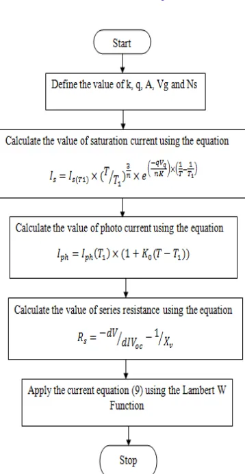
( ) (9)The characteristic of current-voltage is obtained using the equation (9). Fig.2 show the algorithm to the Lambert
W Function used in single diode model of current equation. The first step is considered the value of (k, q, A, Voc and Isc)
from the datasheet. Next step is calculate the value of diode saturation current (Is), generated photocurrent (Iph) and
series resistance (Rs) using the equation (2), (3) and (6) respectively. Applied the current equation(9) as the function of
Fig.2 Flowchart for the algorithm to the Lambert W Function
III. SIMULATION RESULTS
The performance of PV module characteristics using the Lambert W Function operated under different irradiance and different temperature condition. The power produced by a PV module depends on electrical characteristics (current and Voltage) and atmospheric condition. The simulation results obtained in this section are using in MATLAB/Simulink.
The Solar MSX60W PV module (or array) is considered for the simulation study. PV module specifications are shown in Table I. The performance of module operated under Standard Test Condition(STC), the value of solar
irradiance and temperature is considered 1000W/m2 and 25℃ respectively. [4]
Table I. Specifications of Solar MSX60W PV module
Sr No. Parameter Value Unit
1. Open Circuit Voltage (Voc) 21.0 Volts(V)
2. Short Circuit Current (Isc) 3.74 Ampere(A)
3. Voltage at Maximum Power Point (Vm) 17.1 Volts(V)
4. Current at Maximum Power Point (Im) 3.5 Ampere(A)
0 5 10 15 20 0 0.5 1 1.5 2 2.5 3 3.5 4 Voltage (V) C u rr e n t (A ) 0C 50C 25C 75C
0 5 10 15 20
0 0.5 1 1.5 2 2.5 3 3.5 4 Voltage (V) C u rr e n t (A )
G = 0.25 G = 0.50
G = 0.75 G = 1.0
0 5 10 15 20 25 30 0 10 20 30 40 50 60 70 80 Voltage (V) P o w e r (W )
G = 0.25 G = 0.50
G = 0.75 G = 1.0
0 5 10 15 20 25
0 10 20 30 40 50 60 70 Voltage (V) C u rr e n t (A ) 0C 25C 50C 75C
The power produced by a PV module depends on electrical characteristics (current and voltage) and atmospheric condition. The current & voltage relationship of a PV module operating conditions is essentially for the determination of their power output. The current-voltage I-V Characteristic curves at various solar irradiance levels and
Temperatures as in Fig.3 and Fig.4 respectively.[2] The short circuit current (Isc) is defined as when the output voltage
V=0 and the open circuit voltage (Voc) is defined as when the output current I=0. The current (Isc) is proportional the
solar irradiance and at that time voltage (Voc) is increases logarithmically with solar irradiance. If short circuit current increases the solar irradiance is also increases as shown in Fig.3. The temperature is inversely proportional to the voltage (Voc). As temperature increases leads to open circuit voltage is decreased as shown in Fig.4. [2]
Fig.3 Current-Voltage curve of different Fig.4 Current-Voltage curve of different Solar insulation level solar temperature level
The Power-voltage curve for different solar insulation and temperature levels as in Fig.5 and Fig.6
respectively. Figure shows that whenever temperature is increase it leads to decreases the open circuit voltage (Voc)
and slightly increasing the short circuit current(Isc) [2].
IV. CONCLUSION
The simulation results of a photovoltaic device by the Lambert W Function operated under the different environment conditions (irradiance and temperature) is presented. This method is reproduced the characteristics of the single diode model the photovoltaic cell. It is non-iterative method and gives the single iteration, no need the initial value for the parameter calculation. The current-voltage (I-V) and the power-voltage (P-V) curves obtained from this method are matching with the curves drawn from the PV module (Newton’s method) at standard test conditions. Also it described that the Lambert W Function gives the little calculation as compared to the Newton’s method for single diode model.
V. NOMENCLATURE
G = Solar irradiance (W/m2)
k = Boltzmann’s constant (1.38×10⁻²³ J/K)
q = Electronic charge (1.6×10⁻¹⁹ C)
T = Cell temperature of a photovoltaic cell (℃)
I = Output current of a photovoltaic cell (A)
Is = Diode Saturation current (A)
Iph = Light generated Photo-current (A)
A = Diode quality factor
V = Output voltage of a photovoltaic cell (V)
Rs & Rsh = Series and Shunt Resistance
W = Lambert W Function
Isc = PV module of Short circuit current (A)
Voc = PV module of Open circuit Voltage (V)
REFERENCES
(1) E. Batzelis and I. Routsolias, “An Explicit PV String Model Based on the Lambert W Function and simplified MPP Expressions for Operation Under Partial Shading”, IEEE transactions on Sustainable Energy, vol.5, no.1, January-2014.
(2) A. Jakhrani and S. Samo, “An improved Mathematical model for computing power output of solar photovoltaic module”, international journal of photo energy, March-2014.
(3) F. Ghani and M. Duke, “Numerical determination of series and shunt resistances using Lambert W Function”, IEEE photovoltaic specialist conference, pp.002861-002865, 2011.
(4) G. Walker, “Evaluating MPPT Converter Topologies Using a MATLAB PV Model.” Department of computer science and Electrical Engineering, University of Queensland, Australia, vol. 21, pp.49–55, 2001.
(5) Maria Carmela Di Piazza and Gianpaolo Vitale, “Photovoltaic Sources: Modeling and Emulation”, Springer- Verlag London 2013.
(6) I. Chatzigeorgiou, “Bounds on the Lambert Function and Their Application to the outage Analysis of User Cooperation”, IEEE communications letters, vol.17, no.8, pp.1505-1508, August 2013.