Design and FPGA Implementation of
Optimized Parallel Prefix Adder
Anjana D 1, Jemti Jose 2
P.G. Student, Department of Electronics and Communication Engineering, St. Joseph’s College of Engineering and
Technology, Kerala, India1
Assistant Professor, Department of Electronics and Communication Engineering, St. Joseph’s College of Engineering
and Technology, Kerala, India2
ABSTRACT: Binary addition is the frequently used arithmetic operation in most of the digital system. The accurate operation of a digital system is greatly influenced by the performance of adders. Thus improving performance of the digital adder would greatly advance the execution of binary operations. Speed of the adder decides the minimum clock cycle time in a microprocessor. The need for a Parallel Prefix adder is that it is primarily fast when compared with ripple carry adders. Parallel prefix adders are the most efficient circuits for binary addition. Their structure and fast performance makes them attractive for VLSI implementation. Parallel prefix adders (PPA) are family of adders which are derived from the commonly known carry lookahead adders. These adders are mainly used for adders with wider word lengths.
KEYWORDS:Parallel prefix adders, Carry look ahead adders.
I. INTRODUCTION
An adder is an important component of digital computers. Adders are used in many parts of the digital computers. Addition is also a fundamental operation for most of the digital signal processing or control system. They are also used in address calculation, multipliers and other functional units. Therefore the accurate operation of a digital system depends on the performance of adders. Hence for improving the performance of a digital system adder is the main area of research in VLSI system design. This can be achieved by parallel prefix adders (also known as carry-tree adders). There are many types of parallel prefix adders such as Kogge Stone, Brent Kung, Hans Carlson, Ladner Fisher and Knowles Harris. In my work Brent Kung, Kogge Stone, sparse kogge stone and spanning tree adders are investigated and compared with conventional ripple carry adder, carry lookahead adder and carry skip adder. In Very Large Scale Integration (VLSI) designs, Parallel prefix adders (PPA) have the better performance in terms of delay. Different methods are introduced to reduce the delay and area of the above adders thus their computational speed can be improved and area can be reduced. Parallel-prefix adders are known to have the best performance in VLSI designs compared to that of conventional adders.
II. RELATEDWORK
Richard P. Brent et al [1] has discussed an efficient way to reduce the chip area and design cost. The model presented is intended to be general and realistic at the same time to apply current VLSI technology. Here it is assumed that the gates which compute logical function of two inputs in constant time. An output signal can be divided into two signals in constant time and the case of wires are also considered. In this work the area is reduced by maintaining the regularity, regularity of layout is an important criteria in VLSI design, without reducing the number of gates.
of two functions are performed simultaneously in two separate processors. The functions are again splitted to sub functions and are spread over more processors. These algorithms are not applicable to wider class of programs other than the algorithm designed to solve the problem.
Avinash Shrivastava et al [3] suggest different methods for improving the performance of digital adders. The power dissipation, layout area and operating speed of digital circuit blocks are analysed in this paper. Different Parallel Prefix Adders (PPA) such as Kogge Stone, Brent Kung, Lander Fisher, Hans Carlson and Knowles Harris adders are compared and are implemented on FPGA. In these adders the carry bit is computed in parallel, which makes the computation faster. On the basis of area and power it is observed that Knowles Harris adder is the best when compared to other adders.
C H. Ramesh et al [4] implemented different tree based adder structures and compared with Ripple Carry Adder (RCA) and Carry Skip Adder (CSA). The already existing kogge stone adder is modified by reducing the redundant black cells and gray cells, and the removed cells are compensated by rerouting. The delay is much less for the modified design than the existing design and the number of logic levels also gets reduced.
III.BASICADDERUNIT
Adders combine binary values to obtain a sum using combinations of logic gates. The adders are mainly classified according to their ability to accept and combine the digits. The basic arithmetic operation is the addition of two binary digits. A half adder adds two input bits and produces a sum bit and a carry bit. A full adder is constructed using two half adders and it adds three input bits to produce a sum bit and a carry bit. An N-bit binary adder can be created by cascading N full adders. Full adders are cascaded by connecting the carry output of one adder to the carry input of the next adder.
Half Adder
A half adder is a logical circuit that performs an addition operation on two binary input digits. The half adder produces a sum and a carry bit as output. The Boolean logic for a half adder is as follows.
S = A XOR B C = A AND B
One possible implementation is using an AND gate and an XOR gate as shown in Fig .1.
Fig .1. Half Adder Circuit
Full Adder
half adders. The implementation of a full adder is shown in Fig.2.
Fig .2. Full Adder Circuit
IV.TYPESOFADDERS
Different types of adders which are analyzed in this paper are given below
Ripple carry adder or carry propagate adder
Carry look-ahead adder
Carry skip adder
Kogge stone adder
Sparse kogge stone adder
Spanning tree adder
Brent kung adder
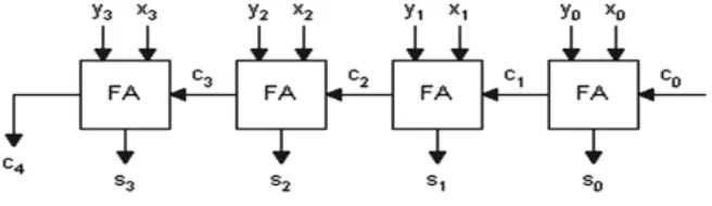
A. Ripple Carry Adder
The ripple carry adder is constructed by cascading full adder blocks in series. One full adder adds two binary digits at any stage of the ripple carry. The carryout of one stage is fed directly to the carry-in input of the next stage. For an n-bit parallel adder, it requires n full adders (FA). Fig. 3 shows a 4-bit ripple-carry adder. It is constructed by cascading four full adders. Each full adder creates a sum and a carry out bit. The carry out is then fed to the carry in of the next higher-order bit. The final result creates a sum of four bits and a carry out.
B. Carry Look Ahead Adder
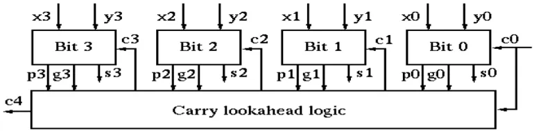
A carry look-ahead adder improves speed by reducing the amount of time required to compute carry bits. Thus it overcomes the disadvantage of ripple carry adder by reducing the time taken to compute carry bit. The CLA solves the problem of delay it takes to propagate the carry, by calculating the carry signal in advance based on the input bits. To understand how the carry look-ahead adder works, we have to manipulate the Boolean expression dealing with the full adder. The Propagate P and generate G in a full-adder, is given as:
Pi = Ai Bi Carry propagate Gi = Ai.Bi Carry generate
Both propagate and generate signals depend only on the input bits and thus will be valid after one gate delay. The new expressions for the output sum bit and the carryout bit are given by:
Si = Pi Ci-1 Ci+1= Gi + PiCi
These equations show that a carry signal will be generated in two cases:
1. If both input bits Ai and Bi are 1
2. If either bit Ai or Bi is 1 and the carry-in bit Ci is 1.
These equations can be applied for a 4-bit adder:
C1 = G0 + P0C0
C2 = G1 + P1C1 = G1 + P1 (G0 + P0C0) = G1 + P1G0 + P1P0C0 C3 = G2 + P2C2 = G2 + P2G1 + P2P1G0 + P2P1P0C0
C4 = G3 + P3C3 = G3 + P3G2 + P3P2G1 + P3P2P1G0 + P3P2P1P0C0
Similarly we can write the general expression as
Ci+1 = Gi + PiGi-1 + PiPi-1Gi-2 +...PiPi-1....P2P1G0 + PiPi-1 ...P1P0C0 Fig. 4 shows a 4bit carry look ahead adder .
Fig .4. carry look ahead adder
C. Carry Skip Adder
Fig .5. Carry skip adder
Equation in terms of the carry in signal for generating carry out bit for carry skip adder is given:
Ck+1 = Gk + Pk .Ck
Also Generate and Propagate signals used by the carry skip adder are:
Gk = Ak . Bk Pk = Ak ⨁ Bk
From this equation, it can be seen that if the carry-in signal of a block is set to zero causes the carry out to serve as a block generate signal. The block generates and block propagates signals produce the input carry to the next block. Fig .5. shows the 8 Bit Carry Skip Adder using 2 bit block of ripple carry adder.
D. Kogge Stone Adder
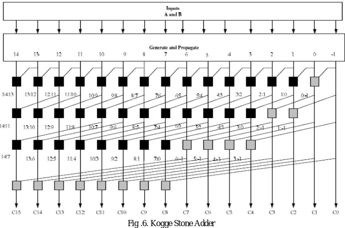
The Kogge Stone Adder (KSA) has regular layout thus it is used in electronic technology. And it is also having a minimum fan-out or minimum logic depth. For this reason, the KSA becomes a fast adder but has a large area. The delay of KSA is equal to log2n which is the number of stages for the “o” operator. The KSA has the area of (n*log 2
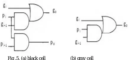
n)-n+1 where n is the number of input bits. KSA is another type of prefix trees that use the fewest logic levels. A 16-bit KSA is shown in Fig .6. The 16 bit kogge stone adder uses Black Cells and Gray Cells and it won’t use full adders. The 16 bit KSA uses 36 Black Cells and 15 Gray Cells, and this adder totally operates on generate and propagate blocks. So the delay is less when compared to the sparse kogge stone adder and spanning tree adder. For KSA there are no full adder blocks like SKA and STA.
Kogge stone adder is a type of parallel prefix adder. The PPA’s pre-computes generate and propagate signals which is the first stage. Using the fundamental carry operator (fco), these computed signals are combined and carry signal is generated, this operation is done on the second stage. The fundamental carry operator is denoted by the symbol “o”, the fco blocks process the generate and propagate bits from the pre-processing structure of the PPA. The fco blocks contain two AND gates and one OR gate which are combined to form black cell and gray cell. The arrangement of these blocks are different for different types of PPA.
E. Sparse Kogge Stone Adder
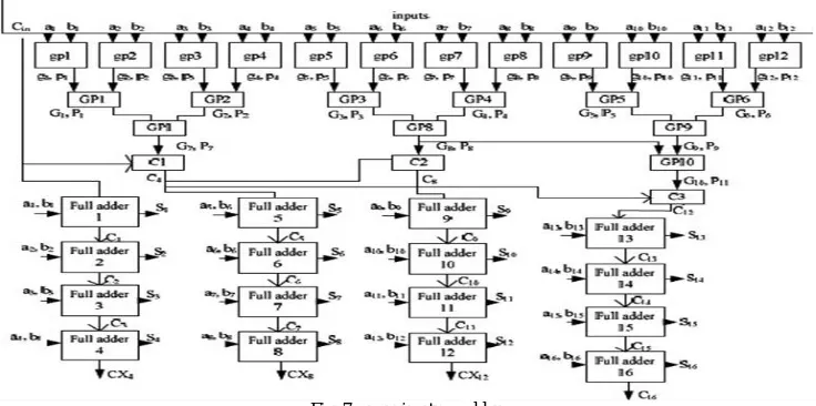
The 16 bit SKA uses black cells and gray cells and full adder blocks too. This adder computes the carries using the BC’s and GC’s and ends with 4 bit RCA’s. For 16 bit sparse kogge stone adder there are 16 full adders. The 16 bit SKA is shown in Fig.7. In this adder, first the input bits are converted as propagate and generate signals.
Fig .6. Kogge Stone Adder
Then propagate and generate bits are given to BC’s and GC’s. The carries are propagated in advance using these black and gray cells. Then these are given to full adder blocks. This hybrid design completes the summation process with a 4 bit RCA allowing the carry prefix network to be simplified. In the basic Sparse Kogge -Stone adder the numbers of cells used are less in number as compared to the Kogge Stone adder and final sum calculated through ripple carry adder.
Fig .7. Sparse Kogge Stone Adder
F. Spanning Tree Adder
Another carry-tree adder known as the spanning tree carry-look ahead (CLA) adder is also analysed. Similar to sparse Kogge-Stone adder, this design terminates with a 4-bit RCA. The only difference from sparse kogge stone adder is in the interconnections between cells. Delay is more when compared to kogge stone adder (KSA). An 8bit spanning tree adder is shown in fig. 7.
Fig .7. spanning tree adder
G.Brent Kung Adder
The large number of levels in Brent Kung Adder (BKA) reduces its operational speed. BKA is also power efficient because of its lowest area and delay for large number of input bits. The delay of BKA is equal to (2*log2n)-2 which is
the number of stages for the operator. The BKA has the area of (2*n)-2-log2n where n is the number of input bits. The
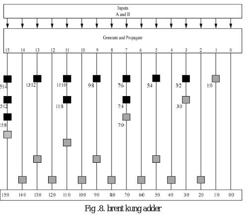
BKA also uses BC’s and GC’s but less when compared to KSA. So it occupies less area than KSA. The 16 bit BKA uses 14 BC’s and 11 GC’s and kogge stone adder uses 36 BC’s and 15 GC’s. So BKA has less architecture than KSA. The 16 bit BKA is shown in the below Fig .8. BKA occupies less area than the other 3 types of adders called SKA, KSA, and STA. And also uses limited number of propagate and generate cells than the other 3 adders. It takes less area to implement than the KSA and has less wiring complexity.
V. MODIFIEDKOGGESTONEADDER
From the analysis of different adders such as ripple carry adder, carry look ahead adder, carry skip adder, kogge stone adder, sparse kogge stone adder, brent kung adder and spanning tree adder it was found that kogge stone adder is showing a better performance in the case of delay and power. This is shown in Table.1. We can further improve the performance by the following methods
Reducing the redundant black cell and gray cell.
Introducing triple carry operator in the critical path.
A. Reducing Redundant Cells.
wires but this is not so effective because area does not change it will remain the same. We can also increase the speed of adder by eliminating redundant black cells which results in reduction in area of the adder. The elimination of cell
Fig .8. brent kung adder
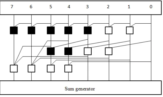
and rerouting are done only on the first and second stage of a kogge stone adder. Reducing the cells of an 8 bit kogge stone adder is shown in Fig.9. This configuration improves the speed and reduces the area of the adder.
B. Using Triple Carry Operator
To improve the speed of operation of a kogge stone adder a new operator named triple carry operator is used. Triple-carry operator, which computes the generate and propagate signals for a merged block which combines three adjacent blocks or cells. We use this by replacing fundamental carry-operator to compute the generate and propagate signals for a merged block combining two adjacent blocks. It reduces the depth of the adder. In addition, we use a ripple-carry type of structure in the non timing critical portion of the parallel prefix adder network.
These techniques help to produce a good timing-area tradeoff characteristic. The results indicate that our proposed adder is significantly faster than the popular Brent–Kung adder and sparse kogge stone adder with some area overhead. The proposed adder also shows faster performance than the fast Kogge–Stone adder with significant time savings. Triple-carry-operator computes the generate and propagate signals for a merged block. This combines three adjacent blocks.
Fig .10. triple carry operator
If three blocks are having the Generate and Propagate value-pairs as (Gleft, Pleft), (Gmid, Pmid) and (Gright, Pright), then the
combined block generates a Carry only if:
• Left block generates a Carry OR
• Middle block generates a Carry and Left block propagates that OR
• Right block generates a Carry and both Middle and Left blocks propagate that Carry.
The combined block propagates only if:
• Each of the three blocks propagates the input Carry.
The GP values of the combined block are as follows
Gleft, right = Gleft + (Pleft * Gmid) + (Pleft * Pmid *Gright)
Pleft, right = Pleft*Pmid *Pright .
Fig .10 shows triple carry operator used in kogge stone adder. The triple carry operator is used in the critical path. The critical path is the MSB bit propagation end and at the LSB bit is propagated to the next stage through fundamental carry operator. Modified kogge stone adder using triple carry operator is shown in Fig.11.
VI.RESULTSANDDISCUSSIONS
The adders are designed in verilog HDL language and synthesized using Xilinx 12.1 ISE design suite and then verified using Spartan 3 FPGA. The power is obtained using XPower analyzer. Simulation result is given below.
VII. SIMULATIONRESULT
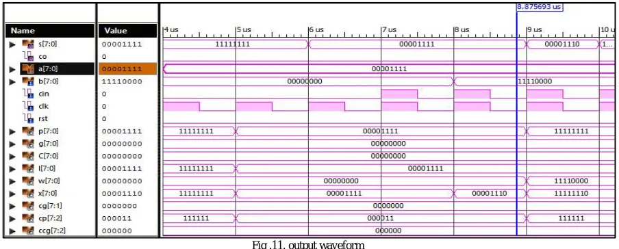
Fig .11. output waveform
The output waveform of an 8bit kogge stone adder for different inputs are shown in fig 11. Adder structures are synthesized using Xilinx 12.1 design suite and simulation result is obtained using ISIM tool.
Comparison Table
Different adders such as ripple carry adder, carry look ahead adder, carry skip adder, kogge stone adder, sparse kogge stone adder, brent kung adder and spanning tree adder were designed in verilog language and are analyzed using Xilinx ISE Design suite 12.1. The power dissipated by different adders are obtained from XPower analyzer and it is observed that kogge stone adder is showing a better performance at 4 bit , even though there is a tradeoff with brent kung adder in the case of delay it is having better performance since the power is less. The area requirement is also comparably less for kogge stone adder
.
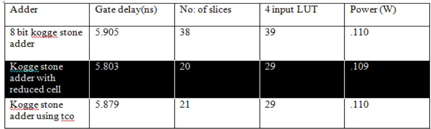
Table 2. comparison table of kogge stone adders
From Table 2 it is observed that kogge stone adder with reduced redundant cells are having less delay, power and area.
VIII. CONCLUSION
Delay, area and power for various adders are analyzed and it is found that the best adder in terms of speed, area and power characteristics is kogge stone adder. And it can be concluded that redesigning of basic operators improve the performance of parallel prefix adders. The delay in adder can be reduced by eliminating the redundant cells or by introducing ripple carry operators. Redundant cells in kogge stone adder are eliminated and triple carry operator is introduced. It is observed that the delay is further reduced while using the former method.
REFERENCES
[1] R. P. Brent and H. T. Kung, “A regular layout for parallel adders”, IEEE trans, computers, Vol.C-31,pp. 260-264,.March 1982.
[2] Kogge P, Stone H, “A parallel algorithm for the efficient solution of a general class Recurrence relations”, IEEE Trans. Computers, Vol.C-22, pp 786-793,Aug. 1973
[3] Avinash shrivastava, Chandrahas sahu,” Performance Analysis of Parallel Prefix Adder Based on FPGA”, International Journal of Engineering Trends and Technology Volume.21,Issue- 6, March 2015
[4] CH.Sudha Rani, CH.Ramesh,” Design and Implementation of High Performance Parallel Prefix Adders”,International Journal of Innovative Research in Computer and Communication Engineering, Vol. 2, Issue 9, September 2014
[5] Tati Padma, K.Krishna Reddy, S.S.G.N.Srinivasa Rao,” Implementation Of High Performance Spanning Tree Adder Using Quaternary Logic”, Global Journal of Advanced Engineering Technologies, August 2014
[6] P.Ramanathan and.P.T.Vanathi ,” Hybrid Prefix Adder Architecture for Minimizing the Power Delay Product”, International Journal of Electrical, Computer, Energetic, Electronic and Communication Engineering, Vol:3, No:4, 2009
[7] Mangesh B Kondalkar, Arunkumar P Chavan, P Narashimaraja,”Improved Fault Tolerant Sparse Kogge Stone Adder”, International Journal of Computer Applications, Volume 75– No.10, August 2013
[8] P.Annapurna Bai, M.Vijaya Laxmi,” Design of 128- bit Kogge-Stone Low Power Parallel Prefix VLSI Adder for High Speed Arithmetic Circuits”, International Journal of Engineering and Advanced Technology, Volume-2, Issue-6, August 2013
[9] Shrinivas K Saptalakar, Manjunath Lakkannavar,”Design and Analysis of 8-bit Low Power Parallel Prefix VLSI Adder”, International Journal of Recent Technology and Engineering, Volume-2, Issue-1, March 2015
[10] D. Harris, “A taxonomy of parallel prefix networks”, IEEE International Conference on computer design, pp.2213.2217, Nov. 2003
[11] Taeko Matsunaga, Shinji Kimura and Yusuka Matsunaga, “Synthesis of parallel prefix adders considering switching activities”, IEEE International Conference on computer design, pp.404-409, 2008