ISSN(Online) : 2319-8753 ISSN (Print) : 2347-6710
I
nternational
J
ournal of
I
nnovative
R
esearch in
S
cience,
E
ngineering and
T
echnology
(An ISO 3297: 2007 Certified Organization)
Vol. 5, Issue 4, April 2016
Some Innovative Concepts of Quick Charging
K.V.Muralidhar Sharma1, Veerendra.G.P2, Manoj Kulkarni.G.P3
Assistant Professor, Department of Mechanical Engineering, Jyothy Institute of Technology, Thathaguni, Bangalore,
India1
Department of Mechanical Engineering, Jyothy Institute of Technology, Thathaguni , Bangalore, India2,3
ABSTRACT : Currently, there are many kinds of batteries available for primary or backup power sources. Among
them, applications of acid battery and lithium ion battery is one of most important devices due to low cost and continuously improving battery technology. However, a well optimized charging process usually requires a complex control circuitry, such as microprocessors, DSP chips or other power electronics controllers. This paper proposes the methods of quick charging system with , particularly focused on a large size lead-acid battery and lithium ion battery. Accordingly, the charging time can be thus reduced than traditional methods, and the battery temperature can remain no significant change.
I.INTRODUCTION
Nowadays, the lead-acid battery and lithium ion battery is widely used in a variety of applications such as electric vehicle, uninterruptible power system (UPS), and emergency power supply, etc. However, some drawbacks, e.g., poor energy density characteristics, long charging time, and short lifetime discourage its further commercial applications. Therefore, the development of optimized algorithm to achieve a rapid chargingor quick charging and prolong the battery lifetime is still an indispensable research issue in industry
Traditional charge methods either use constant current or constant voltage to charge the battery, or mix these two schemes. However, these methods may suffer from low charge efficiency, over-charge, or long charge time, etc. Accordingly, a charging method with a negative pulse discharging current was reported [9]–[11]. However, this may cause unnecessary energy consumption and make the charger bulky. In a conventional charger, the well-known two-stage power converter that provides high power factor input and well regulated output exhibits problem such as circuit complexity and high cost. A rapid charger using a single-stage power converter with an energy recovery cell was therefore proposed [12]. This charger can release the stored energy into the batteries during the positive pulse charge period.
Although it can provide high power factor and charging efficiency, a complex control strategy is necessary for performance so that some difficulty may arise to deliver it into a real world. Most recently, a variable frequency pulse charge system (VFPCS) was proposed to improve the battery-charge response [13].
Unfortunately, it was only suitable for small size of battery such as cellular phone charger.
II.CONCEPTOFNORMALANDQUICK CHARGINGALGORITHM
Traditional lead acid battery charging modes include: 1.Constant Voltage (CV) charge 2.Constant Current (CC) charge 3.Constant Voltage-Constant Current (CV-CC) charge 4. Pulse charge 5.Positive and Negative Pulse charge. For details, it is described as follows [14-19].
a). Constant voltage charge mode:
ISSN(Online) : 2319-8753 ISSN (Print) : 2347-6710
I
nternational
J
ournal of
I
nnovative
R
esearch in
S
cience,
E
ngineering and
T
echnology
(An ISO 3297: 2007 Certified Organization)
Vol. 5, Issue 4, April 2016
Fig. 1 Charging curve using CV mode
b). Constant current charge mode:
The charging curve using CC is shown in Fig. 2. Based on the CC charge, it is feasible that the charging current can be set under the rated current so that it will not be over the rated limit. On the other hand, the charged voltage will depend on the charging current, and the charge time can be easily estimated. However, the drawback is that it may cause over-charge, and the battery temperature may rise up quickly.
Fig. 2 Charging curve using CC mode
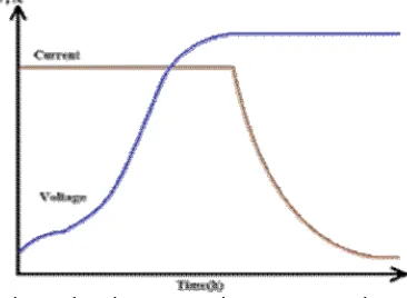
c). Constant Voltage - Constant Current charging mode:
The CV-CC charge mode combines both CV and CC charging method. At the initial charging stage, the constant current is used to charge the battery until the battery voltage reaches over-charged stage or pre-defined voltage. Then, the charging mode will switch to CC one to maintain the battery voltage, avoiding too high voltage. Fig. 3 indicates its charging curve. The advantage of this method is that the charging time can be reduced dramatically. Note that the typical value of maximum charging current is C/10
ISSN(Online) : 2319-8753 ISSN (Print) : 2347-6710
I
nternational
J
ournal of
I
nnovative
R
esearch in
S
cience,
E
ngineering and
T
echnology
(An ISO 3297: 2007 Certified Organization)
Vol. 5, Issue 4, April 2016
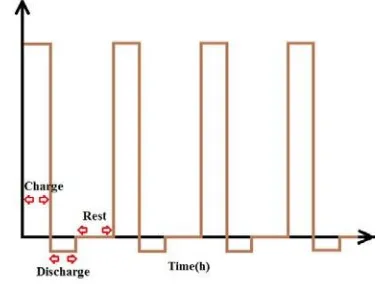
d).Pulse charge mode:
Fig. 4 depicts the profile of pulse charge cycles. Each charging cycle includes “charge” and “rest” stage. In the “charge” period, the battery is charged. In the “rest” period, the battery is at a rest status where the battery has more time to balance the battery chemical reaction. As a result, the battery voltage will become more stable, and its working life can be prolonged. Another advantage is that the charging time can be decreased using a large current which may be over-rated.
Fig.4 Depict of pulse charge
e). Positive and negative pulse charge:
The concept of applying a short discharge pulse during the charge cycle sometimes referred to as "reflex charging" or "burp charging" started with patents 3,597,673 "Rapid charging of batteries" W. Burkett & J. Bigbee in 1971 and 3,614,583 "Rapid charging of batteries" in 1971 by W. Burkett & R. Jackson. Some of the fast charging systems presently available incorporate negative pulse fast charging algorithms that claim to have great benefits to batteries including reduced recharge time, lower temperature rise, full recharge capabilities, as well as shorter equalization times Also, lots of experimental results support that the negative pulse could eliminate the polarization effective. However, this method may reduce charge efficiency [17-19].
Fig. 5 Depict of positive and negative pulse charge
ISSN(Online) : 2319-8753 ISSN (Print) : 2347-6710
I
nternational
J
ournal of
I
nnovative
R
esearch in
S
cience,
E
ngineering and
T
echnology
(An ISO 3297: 2007 Certified Organization)
Vol. 5, Issue 4, April 2016
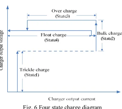
Fig. 6 Four state charge diagram
More details for the four-state charge from Fig. 6 is described as follows, respecting its ideal charge curve, shown in Fig. 5.
State 1 - A pre-charge current ( IT ) is applied to a completely discharged battery until a voltage, VT , is reached. Normally, VT is set low enough so that if a cell is shorted, no high rate charging will commence.
State 2 maximum State 2allowable - The bulk constant charge current, state where IMAX , the is applied to rapidly charge the battery into the overcharge condition. During this time, the majority of the battery capacity is quickly restored. The bulk charge mode is terminated when the battery voltage reaches the over-charge voltage level ( VOC ).
State 3 - When the voltage rises past V12 , an over-voltage state is entered where the battery voltage now applies a constant level, Voc. The initial current value equals the bulk charge current, and as the battery approaches its full capacity, the charge current current becomes will sufficiently taper off. low When ( IOCT the charge ), the charging process is essentially finished and the charger switches over to float charge.
State 4 – During this state, the current will be whatever is necessary to maintain maximum back to State 2 and reapply capacity. If the battery should become loaded, when the voltage falls below V31 , the charger will switch IMAX , initiating a new cycle.
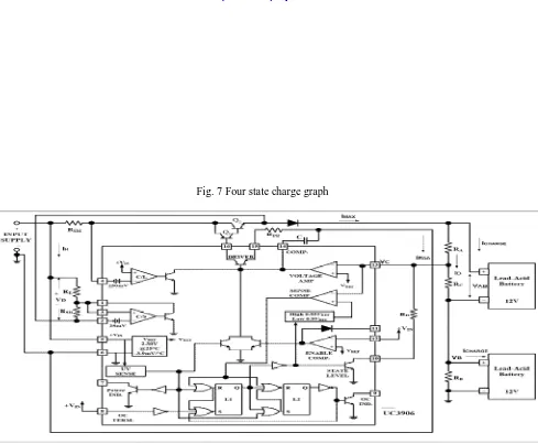
Some critical points in the four state charge diagram are illustrated as follows.
A: When the input supply power turns IT ) on, ratethe to battery charges at trickle current ( avoid the possible short circuit. It is in the state
B: The 1. battery voltage(VAB)reaches VT will enable the driver and turning off the trickle bias output, and then the battery starts to charge at
C: When I MAX ratethe , where it is in the state 2transition voltage V12 .is reached, and the charger indicates that it is now in the over-charge state, i.e., state 3.
D: When the battery VOC voltage , the charge current approaches will the over-charge level
E: When the cbegin to taper.harge current tapers to IOCT . The current sense amplifier output, in this case tied to the OC TERMINATE input, goes high. The charger changes to the float statebattery voltage at VF . and holds the F: Here a load (> IMAX ) begins to discharge the battery.
ISSN(Online) : 2319-8753 ISSN (Print) : 2347-6710
I
nternational
J
ournal of
I
nnovative
R
esearch in
S
cience,
E
ngineering and
T
echnology
(An ISO 3297: 2007 Certified Organization)
Vol. 5, Issue 4, April 2016
Fig. 7 Four state charge graph
III. EXPERIMENTAL RESULTS
The effectiveness of the proposed algorithm has been tested and verified using both two and four series-connected 12V 150AH batteries. Initially, set INPUT SUPPLY voltage=30V, VOC=14V, VF=13.8V and I H =1A for two 12V-battery
charge. Also, choose β1 = 36,β2 = 210 . According to the
equs. (1)-(10), all As can be seen, higher maximum charge current ( I MAX ) reduces the charge time significantly. In contrast, lower maximum charge current (IMAX ) requires more time to achieve the full charge. Obviously, every figure has confirmed a reasonable outcome. For example, 7A charge current , needs more than 8 hours to achieve the full charge. On the other hand, 15A charge current shown in Fig. 13 takes only less than 3 hours to reach a full-charge level. Moreover, in every case the charging
ISSN(Online) : 2319-8753 ISSN (Print) : 2347-6710
I
nternational
J
ournal of
I
nnovative
R
esearch in
S
cience,
E
ngineering and
T
echnology
(An ISO 3297: 2007 Certified Organization)
Vol. 5, Issue 4, April 2016
IV.CONCLUSIONS
This paper has developed a well-optimized fast charger for a large size of lead-acid battery successfully. The proposed method can fast charge the battery using an appropriate large constant current without significant temperature rising. Once the battery reaches the over-charge state, the charger will soon enter a float-charge state where it remains a small holding current. The experimental results confirm that the proposed charger can complete the charging process within 3 hours for both 24V and 48V battery charge. Unlike the conventional complex control circuit, the proposed scheme is superior in term of simplicity, efficiency and low cost. Based on the design procedure,
it can be easily extended to a variety of series batteries charge
ACKNOWLEDGEMENTS
An acknowledgement section may be presented after the conclusion, if desired
REFERENCES
1. Álvarez, J., Marcos, J.; Lago, A.; Nogueiras, A.A.; Doval, J.; Peñalver, C.M., “A fully digital smart and fast lead-acid battery charge system”, IEEE Annual Power Electronics Specialists Conference, Vol. 2, 2003, pp. 913-917.
2. Yang, Kun; Ouyang, Guangyao; Zhang, Ping; Zhang, Jianping, “Research upon the high-capacity lead-acid battery charge model”, 2009 IEEE International Conference on Mechatronics and Automation, 2009, pp. 5079-5083.
3. Chen, W.L.; Li, J.F.; Huang, B.X., “Design of an energy-saving charge equalization system”, Electric Power Components and Systems, Vol. 39, No. 15, 2011, pp. 1632-1646.
4. Taniguchi, Ittetsu; Kojima, Keita; Fukui, Masahiro, “A practical battery charge/discharge simulator for future embedded systems including smart grids”, 2009 International SoC Design Conference, 2009, pp. 173-176.
5. Li, Wen; Zhang, Cheng-Ning, “Experiments study on charge technology of lead-acid electric vehicle batteries”, Journal of Beijing Institute of Technology (English Edition), Vol. 17, No. 2, 2008, pp. 159-163.
6. Ding, K.; Cheng, K.W.E.; Wang, S.X.; Wang, D.H.; Shi, Zhanghai, “Five-level cascaded multilevel motor driver for electrical vehicle with battery charge management”, Australasian Universities Power Engineering Conference, 2008.
7. Chen, Liang-Rui, “PLL-based battery charge circuit topology”, IEEE Transactions on Industrial Electronics, Vol. 51, No. 6, 2004, pp. 1344-1346 8. Chen, Liang-Rui, “A design of an optimal battery pulse charge system by frequency-varied technique”, IEEE Transactions on Industrial Electronics, Vol. 54, No. 1, 2007, pp. 398-405.
9. K. C. Tseng, T. J. Liang, J. F. Chen, and M. T. Chang, “High frequency positive/negative pulse charger with power factor correction,” in Proc. IEEE PESC’02, Vol. 2, 2002, pp. 671-675.
10. P. H. Cheng and C. L. Chen, “A high-efficiency fast charger for lead acid batteries,” in Proc. IEEE IECON’02, Vol. 2, 2002, pp. 1410-1415. 11. E. M. Valeriote, T. G. Chang, and D. M. Jochim, “Fast charging of lead-acid batteries,” in Proc. ABCAA’94 Conf., 1994, pp. 33-38.
12. Huang-Jen Chiu, Li-Wei Lin, Ping-Lung Pan, and Ming-Hsiang Tseng, “A Novel Rapid Charger for Lead-Acid Batteries With Energy Recovery”, IEEE Transactions on Power Electronics, Vol. 21, No. 3, 2006, pp.640-647.
13. Chen, Liang-Rui, Young, Chung-Ming; Chu, Neng-Yi; Liu, Chuan-Sheng, “Phase-locked bidirectional converter with pulse charge function for 42-V/14-V dual-voltage PowerNet”, IEEE Transactions on Industrial Electronics, Vol. 58, No. 5, 2011, pp. 2045-2048.
14. Sohn, W.J., and Chainer, T.J.,“Constant-current versus constant-voltage VCM drive analysis ,” Magnetics, IEEE Transactions on , Vol.26, May 1990, pp.1217-1224.
15. Dickinson and J. Gill, “Issues and benefits with fast charging industrial batteries,” The 15th Annual Battery Conference on Applications and Advances, 1999, pp.223-229.
16. E. M. Valeriote, T. G. Chang, and D. M. Jochim, “Fast charging of lead - acid batteries,” The 9th Annual Battery Conference on Applications and Advances, 1994, pp.33-38.
17. J. J. Wilkinson, G.A. Covic, “A New Pulse Charging Methodology for Lead Acid Batteries”, IPENZ Transactions, Vol. 25, No.1/EMCh, 1998. 18. Li Siguang Li Siguang, Zhang Chengning Zhang Chengning, Xie Shaobo Xie Shaobo,”Research on Fast Charge Method for Lead-Acid Electric Vehicle Batteries”, 2009 International Workshop on Intelligent Systems and Applications, 2009.
19. M. James, J. Grummett, M. Rowan, J. Newman, “Application of pulse charging techniques to submarine lead-acid batteries”, Journal of Power Sources, Vol. 162, Issue 2, Nov. 2006, pp. 878–883