ABSTRACT
LU, XIAOMIN. Nanocellulose as Additive and Reinforcing Agent in Melt-spinning of Polypropylene (under the direction of Dr. Orlando J. Rojas and Dr. Jan Genzer).
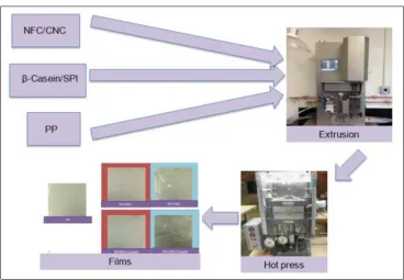
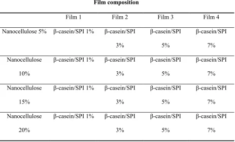
Cellulose nanocrystals (CNC) and nanofibrillar cellulose (NFC) were used in composite films with polypropylene (PP) with the aim of understanding the dispersion of CNC/NFC in the PP matrix. The CNC and NFC used included samples that were isolated from fibers by using standard protocols, acid hydrolysis and mechanical deconstruction, respectively. In addition, commercially-available nanocellulose products were also adopted. Due to the intrinsic hydrophilicity of CNC/NFC, several methods were applied in order to facilitate their incorporation in PP, including surface modification of CNC/NFC and the addition of amphoteric macromolecules (β-casein and soy protein isolate) as well as coupling agents (maleic anhydride polypropylene).
The reinforcing effect of CNC/NFC added to PP at levels of less than 10% was demonstrated. The coupling function of alkenyl succinic anhydride (ASA), stearic acid and maleic anhydride polypropylene (MAPP) was evaluated. Both ASA and MAPP enhanced the compatibility of CNC/NFC with PP. Soy protein isolate, hydroxypropyl cellulose and MAPP were further evaluated as compatibilizers with PP. This work also included lignin-containing NFC and CNC (lignocellulose nanofibrils, LCNF and LCNC) as alternate reinforcing components.
In a second batch, fibers were prepared from a double-screw extruded, diluted masterbatch. The fibers from the second batch exhibited enhanced tensile strength, elongation, toughness and thermal stability. Also, the crystallization process was improved. Thus, the reinforcing effect of CNC/NFC in PP fibers was confirmed.
The effect of lignin in LCNF and LCNC upon addition to PP for further spinning was also investigated. In this case, the loading levels of LCNC/LNFC were in the range between 0.5% and 2.5%. The mechanical and thermal properties of the resultant composite fibers were evaluated and it was concluded that compared to CNC and NFC, LCNC/LNFC displayed similar effects on PP fibers, i.e., melting, crystallinity and molecular orientation. Finally, the effect of lignin as an antioxidant and to control the thermally-induced oxidation of PP was studied. It was found that butylation of lignin macromolecules not only improved their compatibility with PP but afforded systems with improved oxidation induced time (OIT) and thermal-oxidative stability.
Nanocelluloses as Additive and Reinforcing Agent in Melt-Spinning of Polypropylene
by Xiaomin Lu
A dissertation submitted to the Graduate Faculty of North Carolina State University
in partial fulfillment of the requirements for the degree of
Doctor of Philosophy
Forest Biomaterials
Raleigh, North Carolina 2016
APPROVED BY:
_______________________________ _______________________________
Dr. Orlando J. Rojas Dr. Jan Genzer
Co-Chair of Advisory Committee Co-Chair of Advisory Committee
_______________________________ _______________________________
Dr. Kirill Efimenko Dr. Behnam Pourdeyhimi
DEDICATION
I would like to dedicate this dissertation to my parents, Shifa Lu and Wei Zhang, for all their
BIOGRAPHY
Xiaomin Lu was born on August 19, 1987 in Zoucheng, Shandong Province, China. She received her Bachelor’s degree in pulping and papermaking engineering from Qilu University of Technology (Shandong Institute of Light Industry). After graduation from her home university, she went to Finland to continue her study at Abo Akademi University and obtained her master degree in wood and paper science from the department of chemical engineering. After graduation from her Master, she did one year research at Aalto University and then moved
to Raleigh, North Carolina, USA in January 2013, to start her PhD in Forest Biomaterials under
ACKNOWLEDGMENTS
During my studies of PhD, I have many special thanks to certain people who I met and helped me finish my last episode of my school life.
First, I would like to express my deepest gratitude to my supervisors Dr. Orlando Rojas and Dr. Jan Genzer for their support and guidance toward the progress of my PhD studies. They have always been considerate and father-like throughout my entire PhD life. I’m very lucky and appreciated to get this opportunity to work with them.
I would like to extend my acknowledgement to my advisors Dr. Kirill Efimenko and Dr. Behnam Pourdeyhimi for their inspiring and encouraging guidance and their insightful comments during the entire process of this dissertation. I am thankful to Dr. Don Shiffler for his valuable feedbacks on my presentation skills during Industrial Advisory Board meetings. I also want to thank my industrial advisors Carl Wust, Bernard Hill, Brian Prevofor, Andrew Goodby, Lalith Suragani Venu and Patrick Young for their valuable feedbacks and suggestions.
I want to take this opportunity to thank all my dear friends and staffs who helped and supported me at the Department of Forest Biomaterial, College of Textile and Department of Chemical & Biomolecular Engineering.
TABLE OF CONTENTS
LIST OF TABLES ... xiv
LIST OF FIGURES ... xvi
LIST OF PUBLICATIONS ... xxviii
1. Introduction ...1
1.1 CHEMICAL COMPONETS IN WOOD MATERIALS ... 1
1.1.1 Cellulose ... 2
1.1.2 Hemicellulose ... 15
1.1.3 Lignin ... 17
1.2 SURFACE MODIFICATOIN ... 17
1.2.1 “Grafting onto” and “grafting from” ... 18
1.2.2 Chemisorption ... 18
1.2.3 Physisorption ... 19
1.3 NONWOVEN MANFACTURING PROCESS ... 21
1.3.1 Dry-laid technology ... 21
1.3.2 Wet-laid technology ... 23
1.3.3 Spun-laid technology ... 23
1.4 POLYMER BLENDS ... 28
1.5 COMPOSITE PRODUCTION ... 30
1.5.1 Solvent casting ... 30
1.5.2 Melt compounding ... 30
1.6 REINFORCEMENT OF NANOCELLULOSES IN BIOCOMPOSITES ... 31
1.6.1 Effects of fillers/reinforcements-functions ... 32
1.6.3 Kinetics of aggregation formation ... 35
1.6.4 Effect of microfibrillated lignocellulose on polymers ... 36
1.6.5 Reinforcement of nanocelluloses in hydrophobic polymers ... 37
1.7 REFERENCES ... 40
2. Research Objectives ...52
3. Preparation and characterization of polypropylene and nanocelluloses composite film .53 3.1 ABSTRACT ... 53
3.2 INTRODUCTION ... 53
3.3 EXPERIMENTAL ... 55
3.3.1 Materials ... 55
3.3.2 Methods ... 55
3.4 RESULTS AND DISCUSSIONS ... 60
3.4.1 Morphology of composite films produced via solvent casting and EHP process I, II and II ... 60
3.4.2 Thermo-stability of films produced via solvent casting and EHP process I, II and III ... 66
3.4.3 Thermomechanical properties of films produced via solvent casting and EHP process I, II and III ... 69
3.5 SUMMARY AND CONCLUSIONS ... 74
3.6 REFERENCES ... 76
4. Compatibility of Cellulose Nanocrystals with Polypropylene Using Different Kinds of Chemicals ...78
4.1 ABSTRACT ... 78
4.2 INTRODUCTION ... 78
4.3.2 Methods ... 81
4.4 RESULTS AND DISSCUSIONS ... 84
4.4.1 Characterization of the CNCs ... 84
4.4.2 Thermal transitions ... 85
4.4.3 Shear viscosity of composite melts ... 86
4.4.4 Thermal-mechanical properties of composite films ... 90
4.4.5 Crystalline structure of PP and PP composites ... 93
4.5 SUMMARY AND CONCLUSIONS ... 95
4.6 REFERENCES ... 96
5. Reinforcement of Polypropylene with Lignocellulose Nanofibrils (LCNF) and Compatibilization with Biobased Polymers ...101
5.1 ABSTRACT ... 101
5.2 INTRODUCTION ... 101
5.3 EXPERIMENTAL ... 106
5.3.1 Materials ... 106
5.3.2 Methods ... 107
5.4 RESULTS AND DISSCUSIONS ... 110
5.4.1 Thermal behavior. ... 110
5.4.2 DSC profile sand crystallinity. ... 113
5.4.3 Chemical analyses. ... 116
5.4.4 Mechanical performance ... 120
5.5 SUMMARY AND CONCLUSIONS ... 122
6. Nanocellulose as Additive and Reinforcing Agent in Melt Spinning of
Polypropylene ...136
6.1 ABSTRACT ... 136
6.2 INTRODUCTION ... 136
6.3 EXPERIMENTAL ... 139
6.3.1 Materials ... 139
6.3.2 Methods ... 140
6.4 RESULTS AND DISSCUSIONS ... 143
6.4.1 CNC and NFC morphology ... 143
6.4.2 Shear viscosity of PP and its composites ... 144
6.4.3 Birefringence ... 147
6.4.4 Tensile properties of PP and composite fibers ... 152
6.4.5 Thermal stability of PP and PP composite fibers ... 153
6.4.6 Thermal transitions of composite ... 154
6.5 REFERENCES ... 164
7. The Impotence of Good Dispersion of Nanocellulose in Polypropylene ...168
7.1 ABSTRACT ... 168
7.2 INTRODUCTION ... 168
7.3 EXPERIMENTAL ... 171
7.3.1 Materials ... 171
7.3.2 Methods ... 171
7.4 RESULTS AND DISSCUSIONS ... 175
7.4.1 CNC and NFC morphology ... 175
7.4.4 Birefringence ... 180
7.4.5 Tensile properties of PP and composite fibers ... 181
7.4.6 Thermal stability of PP and PP composite fibers ... 182
7.4.7 Thermal transitions of composite ... 183
7.4.8 Crystalline morphology and crystal size ... 188
7.5 SUMMARY AND CONCLUSIONS ... 192
7.6 REFERENCES ... 193
8. Effects of Lignocellulose Nanocrystal and Lignocellulose Nanofibril as Reinforcing Agents in Melt Spinning of Polypropylene Fiber ...198
8.1 ABSTRACT ... 198
8.2 INTRODUCTION ... 198
8.3 EXPERIMENTAL APPROACH ... 202
8.3.1 LCNC and LNFC morphology ... 202
8.3.2 PP, MAPP and LCNC/LNFC master batch ... 202
8.3.3. Melt spinning PP-MAPP-LCNC/LNFC composite fibers ... 203
8.3.4 Characterization of the composite fibers ... 203
8.4 RESULTS AND DISSCUSIONS ... 206
8.4.1 LCNC and LNFC morphology ... 206
8.4.2 Fiber structure ... 206
8.4.3 Birefringence ... 207
8.4.4 Tensile properties of PP and composite fibers ... 213
8.4.5 Thermal stability of PP and PP composite fibers ... 216
8.4.6 Thermal transitions of composite ... 223
8.5 SUMMARY AND CONCLUSIONS ... 237
9. Antioxidant and Thermal Stabilization Effects of Butylated-Lignin ...244
9.1 ABSTRACT ... 244
9.2 INTRODUCTION ... 244
9.3 EXPERIMENTAL ... 246
9.3.1 Materials ... 246
9.3.2 Methods ... 247
9.4 RESULTS AND DISSCUSIONS ... 251
9.4.1 Lignin butylation and degree of substitution. ... 251
9.4.2 Morphology of films and lignin compatibility with PP ... 254
9.4.3 Antioxidant effect of butylated lignins ... 256
9.4.4 Thermal-oxidative stability ... 258
9.4.5 Thermal stability of lignin/PP films ... 260
9.5 SUMMARY AND CONCLUSIONS ... 263
9.6 REFERENCES ... 265
9.7 SUPPORTING INFORMATION ... 269
LIST OF TABLES
Table 1.1 Size of CNCs obtained from various sources by different techniques[28] ...8
Table 1.2 Continued ...9
Table 1.3 Properties of CNCs and several other reinforcing agents[30] ...10
Table 3.1 Film composition made in process III ...58
Table 3.2 DSC thermal data for PP and PP-CNC composites ...87
Table 5.1. Tonset and DTG of composites with PP and LCNF/(HPC/MAPP/SPI). The % LCNF is based on the PP mass while that for SPI, HPC and MAPP are relative to the LCNF mass...112
Table 5.2. Values of transition temperatures, associated heat of fusion and degree of crystallinity (!") for PP/LCNF/HPC/MAPP/SPI composites. ...114
Table 5.3. Values of the degree of crystallinity (%) for PP/LCNF/HPC/MAPP/SPI composites calculated by FTIR. The values obtained from density data (Eq. 2) are also include as a reference. ...119
Table 5.4. Mechanical properties of PP/LCNF/(HPC/MAPP/SPI) composites. The % LCNF is based on the PP mass while that for SPI, HPC and MAPP are relative to the LCNF mass...121
Table 6.1 Birefringence of PP and composite fibers containing CNCs/NFCs. ...146
Table 6.2 Thermal data from DSC measurements for PP composite fibers. ...157
Table 6.3 Parameters of isothermal crystallization from Avrami equation (t1/2: the crystallization half time, n: Avrami exponent, k: crystallization rate constant) ...162
Table 7.1 Birefringence of PP and composite fibers containing CNCs/NFCs. ...177
Table 7.3 Parameters of isothermal crystallization from Avrami equation (t1/2: the
crystallization half time, n: Avrami exponent, k: crystallization rate constant) ...190 Table 7.4 Crystal size of neat PP and PP composite fibers. ...191 Table 8.1 Birefringence of PP and composite fibers containing LCNCs/LNFCs. ...207 Table 8.2 Onset degradation temperature of PP and composite fibers containing
LCNCs/LNFCs. ...219 Table 8.3 Thermal data from DSC measurements for PP composite fibers. ...224 Table 8.4 Parameters of isothermal crystallization from Avrami equation (t1/2: the
LIST OF FIGURES
Figure 1.1 Average percentage of cellulose, hemicellulose, lignin and other component in
wood materials[3]. ...2
Figure 1.2 Cellulose structure. Stereochemical (a), abbreviated (b), Haworth perspective (c), and Mills’ perspective (d) formulas[5]. ...3
Figure 1.3 Structures of cellulose Iβ, Iα, II, and IIII illustrating differences in chain tilt, packing and hydrogen bonding[8] ...4
Figure 1.4 Interconversion pathways for cellulose polymorphs ...6
Figure 1.5 The mechanism of spray drying process for nanocelluloses[54]. ...14
Figure 1.6 The sugar units of hemicelluloses. Glc: glucose, Man: mannose, Gal: galactose, Xyl: xylose, Ara: arabinose, Rha: rhamnose, Fuc: fucose, f: furanose, p: pyranose, U: uronic acid[5]. ...16
Figure 1.7 The building units of lignin[63]. ...17
Figure 1.8 Schematic for surface modification: (A) physisorption (“grafting onto” method); (B) chemisorption (“grafting onto” method); (C) “grafting from” method[65]. ...19
Figure 1.9 Carding cylinders with roller top card[79]. ...21
Figure 1.10 Web forming on the forming wire conveyor[79]. ...22
Figure 1.11 Web forming on the screen drum of a Rando-Webber machine[78]. ...22
Figure 1.12 Illustration of nonwoven wet-laid web formation[79]. ...23
Figure 1.13 Schematic of a typical spunbond process with a belt collector[87]. ...26
Figure 1.14 Illustration of meltblowing technology[78]. ...27
Figure 3.1 Schematic illustration for Process I ...57
Figure 3.3 PP film with freeze-dried NFC and β-casein incorporation made by EHP ...60
Figure 3.4 PP film made by solvent casting from xylene ...60
Figure 3.5 PP film with freeze-dried NFC incorporation made by extrusion with hot press followed by (EHP) ...60
Figure 3.6 PP film with CNC suspension incorporation made by EHP ...60
Figure 3.7 PP film with NFC suspension incorporation made by EHP ...60
Figure 3.8 PP film with NFC suspension and β-casein incorporation made by EHP ...60
Figure 3.9 PP film with CNC suspension and β-casein incorporation made by EHP ...60
Figure 3.10 Neat PP film made by EHP ...61
Figure 3.11 EHP PP films with NFC and SPI loading. Film A composition: PP+5%NFC+1%SPI; Film B composition: PP+5%NFC+3%SPI; Film C composition: PP+5%NFC+5%SPI; Film D composition: PP+5%NFC+7%SPI ...62
Figure 3.12 EHP PP films with NFC and SPI. Film A composition: PP+10%NFC+1%SPI; Film B composition: PP+10%NFC+3%SPI; Film C composition: PP+10%NFC+5%SPI; Film D composition: PP+10%NFC+7%SPI ...62
Figure 3.13 EHP PP films with NFC and SPI. Film A composition: PP+15%NFC+1%SPI; Film B composition: PP+15%NFC+3%SPI; Film C composition: PP+15%NFC+5%SPI; Film D composition: PP+15%NFC+7%SPI ...62
Figure 3.15 EHP PP films with CNC and SPI loading. Film A composition:
PP+5%CNC+1%SPI; Film B composition: PP+5%CNC+3%SPI; Film C composition: PP+5%CNC+5%SPI; Film D composition: PP+5%CNC+7%SPI ...63 Figure 3.16 EHP PP films with CNC and SPI loading. Film A composition:
PP+10%CNC+1%SPI; Film B composition: PP+10%CNC+3%SPI; Film C composition: PP+10%CNC+5%SPI; Film D composition: PP+10%CNC+7%SPI ...63 Figure 3.17 EHP PP films with CNC and SPI loading. Film A composition:
PP+15%CNC+1%SPI; Film B composition: PP+15%CNC+3%SPI; Film C composition: PP+15%CNC+5%SPI; Film D composition: PP+15%CNC+7%SPI ...64 Figure 3.18 EHP PP films with CNC and SPI loading. Film A composition:
Figure 3.22 Cryo-fractured of CNC-based composite films produced via EHP process III. Film A composition: PP+10%CNC+1%SPI; Film B composition: PP+10%CNC+3%SPI; Film C composition: PP+10%CNC+5%SPI; Film D composition: PP+10%CNC+7%SPI ....65 Figure 3.23 Thermogravimetric analysis (TGA) profiles for solvent casted PP, EHP PP, EHP PP/NFC, EHP PP/NFC/β-casein, EHP PP/CNC and EHP PP/CNC/β-casein. ...66 Figure 3.24 TGA images for the degradation of EHP PP and EHP with different NFC and SPI loading. ...67 Figure 3.25 TGA images for the degradation of NFC, CNC and SPI ...67 Figure 3.26 TGA images for the degradation of EHP PP and EHP with different CNC and SPI loading. ...69 Figure 3.27 Dynamic mechanical analysis (DMA) images for solvent casting PP, EHP PP, EHP PP/NFC, EHP PP/NFC/β-casein, EHP PP/CNC and EHP PP/CNC/β-casein. ...70 Figure 3.28 Differential scanning calorimetry (DSC) images for solvent casting PP, EHP PP, EHP PP/NFC, EHP PP/NFC/β-casein, EHP PP/CNC and EHP PP/CNC/β-casein. ...70 Figure 3.29 DMA images for the storage modulus of EHP PP and EHP with different NFC and SPI loading. ...71 Figure 3.30 DSC images for the melting and crystallization of EHP PP and EHP with
different NFC and SPI loading. ...72 Figure 3.31 DMA images for the storage modulus of EHP PP and EHP with different CNC and SPI loading. ...73 Figure 3.32 DSC images for the melting and crystallization of EHP PP and EHP with
Figure 3.33 FTIR spectra of CNCs, ASA treated CNCs using Method I, SA treated CNCs using Method I, ASA treated CNCs using Method II and MAPP treated CNCs using Method III. ...85 Figure 3.34 Melting endotherms of CNCs, ASA-treated CNCs using Method I, SA-treated CNCs using Method I, ASA-treated CNCs using Method II and MAPP-treated CNCs using Method IV. ...88 Figure 3.35 Heat curves for crystallization exotherms of CNCs, ASA-treated CNCs using Method I, SA-treated CNCs using Method I, ASA-treated CNCs using Method II and
MAPP-treated CNCs using Method IV. ...89 Figure 3.36 Shear viscosity (230°C, advanced capillary extrusion) of PP and PP in the
presence of ASA-treated CNCs using Method I and MAPP-treated CNCs using Method IV. ...90 Figure 3.37 Storage modulus of PP and PP reinforced with ASA-treated CNCs using Method I, SA-treated CNCs using Method I, ASA-treated CNCs using Method II and MAPP-treated CNCs using Method IV. ...92 Figure 3.38 XRD profiles of PP and PP reinforced by ASA-treated CNCs using Method I, SA-treated CNCs using Method I, ASA-treated CNCs using Method II and MAPP-treated CNCs using Method IV. ...94 Figure 5.1. Height AFM images (3 µm x 3 µm) of LCNF before (left) and after (right)
respectively. SPI, HPC or MAPP are indicated as the compatibilizers used. Magnified views of some of the thermograms are also included. The initial mass loss for LCNF due to
evaporation of the absorbed moisture was not recorded. ...113 Figure 5.3. DSC curves of PP-based composites with 1% and 3% LCNF loading (top and bottom panels, respectively) and compatibilizer (SPI, HPC or MAPP) in the crystallization (left) and melting transitions (middle). Magnified regions of the DSC profiles are included on the right. ...117 Figure 5.4. FTIR spectra of LCNF before and after freeze-milling (a); neat PP and the PP-based composites with 1% (b) and 3% (c) LCNF with and without compatibilizer (SPI, HPC or MAPP). ...118 Figure 5.5. Values for the degree of crystallinity calculated by using different methods (DSC, FTIR and density). The horizontal dotted line corresponds to the crystallinity of neat PP crystallinity and is added as a reference. ...120 Figure 6.1 The morphology of CNC (left) and NFC (right) used in this period. ...144 Figure 6.2 Shear viscosity of PP and composite fibers containing CNC (left) and NFC
Figure 6.6 Toughness of PP-MAPP-CNC composite fibers (left) and PP-MAPP-NFCsfibers (right). ...153 Figure 6.7 Stress–strain curves PP and PP composite fibers under tensile deformation. ...153 Figure 6.8 Themal stability of PP-MAPP-CNC (a, b) and PP-MAPP-NFC (c, d) composite fibers. ...154 Figure 6.9 Heat capacity curves for melting endotherms of PP-MAPP-CNCs composite fibers (left) and PP-MAPP-NFCs fibers (right). ...155 Figure 6.10 Heat capacity curves for crystallization exotherms of PP-MAPP-CNCs
composite fibers (left) and PP-MAPP-NFCs fibers (right). ...156 Figure 6.11 Non-isothermal crystallization of MACNC composite fibers (left) and PP-MAPP-NFC fibers (right) at a cooling rate of 10°C. ...158 Figure 6.12 Plots of ln(–ln(1–Xt)) versus ln t for isothermal crystallization of PP and
composite fibers with CNC/NFC loading ranging 0.5-3.5%. ...159 Figure 7.1 The morphology of CNC (left) and NFC (right) used in this period. ...175 Figure 7.2 Shear viscosity of PP and composite fibers containing CNC (left) and NFC
Figure 7.6 Tenacity of PP-MAPP-CNC composite fibers (left) and PP-MAPP-NFC fibers (right). ...181 Figure 7.7 Toughness of PP-MAPP-CNC composite fibers (left) and PP-MAPP-NFCs fibers (right). ...182 Figure 7.8 Elongation of PP-MAPP-CNC composite fibers (left) and PP-MAPP-NFCs fibers (right). ...182 Figure 7.9 Themal stability of PP-MAPP-CNC (a, b) and PP-MAPP-NFC (c, d) composite fibers. ...183 Figure 7.10 Heat capacity curves for melting endotherms of PP-MAPP-CNCs composite fibers (left) and PP-MAPP-NFCs fibers (right). ...185 Figure 7.11 Heat capacity curves for crystallization exotherms of PP-MAPP-CNCs
composite fibers (left) and PP-MAPP-NFCs fibers (right). ...185 Figure 7.12 Avrami plots of ln (1-(1-Xt)) as a function of ln t for neat PP and PP composite fibers ...187 Figure 7.13 X-ray diffractograms of CNCs composite fibers (left) and PP-MAPP-NFCs fibers (right). ...189 Figure 8.1 The morphology of LCNC (left) and LNFC (right) used in this period. ...206 Figure 8.2 Optical micrographs of PP fibers (a) and composite PP fibers containing(b)
PP+2%MAPP+0.5% LCNC, (c) PP+2%MAPP+1.5% LCNC, (d) PP+2%MAPP+2.5% LCNC, (e) PP+5%MAPP+0.5% LCNC, (f) PP+5%MAPP+1.5% LCNC, (g)
PP+5%MAPP+2.5% LCNC, (h) PP+7%MAPP+0.5% LCNC, (i) PP+7%MAPP+1.5%
Figure 8.3 Optical micrographs of PP fibers (a) and composite PP fibers containing (b) PP+2%MAPP+0.5% LNFC, (c) PP+2%MAPP+1.5% LNFC, (d) PP+2%MAPP+2.5% LNFC, (e) PP+5%MAPP+0.5% LNFC, (f) PP+5%MAPP+1.5% LNFC, (g)
PP+5%MAPP+2.5% LNFC, (h) PP+7%MAPP+0.5% LNFC, (i) PP+7%MAPP+1.5% LNFC, (j) PP+7%MAPP+2.5% LNFC. ...210 Figure 8.4 SEM surface images of PP fibers (a) and composite PP fibers containing (b) PP+2%MAPP+0.5% LCNC, (c) PP+2%MAPP+1.5% LCNC, (d) PP+2%MAPP+2.5% LCNC, (e) PP+5%MAPP+0.5% LCNC, (f) PP+5%MAPP+1.5% LCNC, (g)
PP+5%MAPP+2.5% LCNC, (h) PP+7%MAPP+0.5% LCNC, (i) PP+7%MAPP+1.5%
LCNC, (j) PP+7%MAPP+2.5% LCNC. ...211 Figure 8.5 SEM surface images of PP fibers (a) and composite PP fibers containing, (b) PP+2%MAPP+0.5% LNFC, (c) PP+2%MAPP+1.5% LNFC, (d) PP+2%MAPP+2.5% LNFC, (e) PP+5%MAPP+0.5% LNFC, (f) PP+5%MAPP+1.5% LNFC, (g)
PP+5%MAPP+2.5% LNFC, (h) PP+7%MAPP+0.5% LNFC, (i) PP+7%MAPP+1.5% LNFC, (j) PP+7%MAPP+2.5% LNFC. ...212 Figure 8.6 Tenacity of PP-2%MAPP-LCNC composite fibers (top left), PP-5%MAPP-LCNC composite fibers (top right) and PP-7%MAPP-LCNC composite fibers (bottom left)
Figure 8.8 Elongation of PP-2%MAPP-LCNC composite fibers (top left), PP-5%MAPP-LCNC composite fibers (top right) and PP-7%MAPP-PP-5%MAPP-LCNC composite fibers (bottom left) (right). ...215 Figure 8.9 Tenacity of PP-2%MAPP-LNFC composite fibers (top left), PP-5%MAPP-LNFC composite fibers (top right) and PP-7%MAPP-LNFC composite fibers (bottom left)
(right). ...216 Figure 8.10 Toughness of PP-2%MAPP-LNFC composite fibers (top left), PP-5%MAPP-LNFC composite fibers (top right) and PP-7%MAPP-PP-5%MAPP-LNFC composite fibers (bottom left) (right). ...217 Figure 8.11 Elongation of PP-2%MAPP-LNFC composite fibers (top left), PP-5%MAPP-LNFC composite fibers (top right) and PP-7%MAPP-PP-5%MAPP-LNFC composite fibers (bottom left) (right). ...218 Figure 8.12 Themal stability of 2%MALCNC (a), 5%MALCNC (b), LCNC (c), PP-2%MAPP-LNFC (d), PP-5%MAPP-LNFC (e) and PP-7%MAPP-LNFC (f) composite fibers. ...220 Figure 8.13 Heat capacity curves for melting endotherms of PP-2%MAPP-LCNC composite fibers (left), PP-5%MAPP-LCNC composite fibers (middle) and PP-7%MAPP-LCNC
composite fibers (right). ...225 Figure 8.14 Heat capacity curves for melting endotherms of PP-2%MAPP-LNFC composite fibers (left), PP-5%MAPP-LNFC composite fibers (middle) and PP-7%MAPP-LNFC
Figure 8.15 Heat capacity curves for crystallization exotherms of PP-2%MAPP-LCNC composite fibers (left), PP-5%MAPP-LCNC composite fibers (middle) and PP-7%MAPP-LCNC composite fibers (right). ...225 Figure 8.16 Heat capacity curves for crystallization exotherms of PP-2%MAPP-LNFC
composite fibers (left), PP-5%MAPP-LNFC composite fibers (middle) and PP-7%MAPP-LNFC composite fibers (right). ...226 Figure 8.17 Avrami plots of ln (1-(1-Xt)) as a function of ln t for neat PP and PP composite fibers. ...227 Figure 9.1 FTIR- ATR spectra of reference Kraft lignin (KL) and butylated KL lignins
(ML1-ML5, see also Table 9.1) in the wavenumber region between 2500 and 4000 cm-1 showing the redshift in the hydroxyl band (a). The wavenumber region between 650 and 1850 cm-1 is displayed in (b) ...251 Figure 9.2 Quantitative 31P-NMR spectra of reference lignin KL and butylated lignins (ML) obtained after reaction under different conditions. ...253 Figure 9.3 SEM micrographs (10 mm size marker) of pure PP, 1wt% KL/PP and 1wt% butylated KL/PP correlated with KL and butylated ML samples phenolic and aliphatic
hydroxyl group content. ...256 Figure 9.4 Effect of total phenolic hydroxyl group content on the mean oxidative induction time (OIT) for films of neat PP and PP films loaded with 1wt% KL or butylated ML lignins of given substitution degree. ...258 Figure 9.5 Changes in the carbonyl group FTIR intensity as a function of ageing time (120
intensity of carbonyl bands (carbonyl index) measured for different ML samples and loadings as well as for a commercial antioxidant (Irganox 1010), as indicated (b). ...261 Figure 9.6 TG spectra of PP films with 1wt% reference KL and butylated lignin under
LIST OF PUBLICATIONS
1. Lu Xiaomin, Genzer Jan, Efimenko Kirill, Pourdeyhimi Behnam, Rojas Orlando. “Compatibility of Cellulose Nanocrystals with Isotactic Polypropylene Using Different Chemicals”. (In preparation)
2. Lu Xiaomin, Ferrer Ana, Ye Dezhan, Genzer Jan, Efimenko Kirill, Pourdeyhimi Behnam, Rojas Orlando. “The Importance of Good Dispersion of Nanocellulose in Melt Spinning Polypropylene Fiber Production”. (In preparation)
3. Lu Xiaomin, Genzer Jan, Efimenko Kirill, Pourdeyhimi Behnam, Rojas Orlando. “Effects of Lignocellulose Nanocrystal and Lignocellulose Nanofibril as Reinforcing Agents in Melt Spinning of Polypropylene Fiber”. (In preparation)
4. Lu Xiaomin, Genzer Jan, Efimenko Kirill, Pourdeyhimi Behnam, Rojas Orlando. “Polypropylene and nanocellulose composite film preparation and characterization”. (In preparation)
5. Ferrer Ana, Hoeger Ingrid, Lu Xiaomin, Rojas Orlando, (2016). “Reinforcement of Polypropylene with Lignocellulose Nanofibrils (LCNF) and Compatibilization with Biobased Polymers” Journal of Applied Polymer Science, 133, 43854.
6. Ye Dezhan, Li Shuai, Lu Xiaomin, Zhang Xi, Rojas Orlando. “Antioxidant and thermal stabilization effects of butylated-lignin” ACS Sustainable Chemistry & Engineering, Accepted (2016)
Contribution not included in this dissertation: 1. Nanocellulose as additive in wellbore fluids
1. Introduction
Polymers from bioresources have attracted an increasing amount of attention over the last two decades, predominantly due to the environmental concerns and the finite petroleum source. In order to overcome the environment and sustainability problems, remarkable achievements have been observed in green chemistry in terms of the investigation of biocomposites[1, 2]. For example, plenty of work have been carried out to replace conventional petrochemical platforms by biorefineries and the increased use of bio-based polymers and materials have gained much momentum. The development of materials derived from natural resources has a growing trend in the drive to protect our environment. There has been a great interest in polymer reinforced with natural fibers in recent years. Although the production has been investigated for several years, intensive research is still going on in this field to improve the composite properties and produce cheaper materials with good performance.
Three main components making up lignocellulosic biomass are cellulose, hemicellulose and lignin.
1.1 CHEMICAL COMPONETS IN WOOD MATERIALS
low-molecular-mass compounds are for example extractives, and some water-soluble organics and inorganics[5].
Figure 1.1 Average percentage of cellulose, hemicellulose, lignin and other component in wood materials[3].
1.1.1 Cellulose
Cellulose is the predominant compound in wood with a polymerization degree of 1,000-30,000 in its native state. It was firstly discovered and isolated by Payen A. in 1838[6]. Cellulose is the most abundant natural polysaccharide composed of β-D-glucopyronose linked together by (1-4)-glucosidic bonds in the equatorial position (Fig. 1.2). In its structure, there are two OH-groups at the ends: one (C1-OH) has reducing property and the other one (C4-OH) is
non-reducing. C1-OH is an aldehyde hydrate group, whereas C4-OH is an alcoholic hydroxyl[5]. In
Figure 1.2 Cellulose structure. Stereochemical (a), abbreviated (b), Haworth perspective (c), and Mills’ perspective (d) formulas[5].
Cellulose is polymorphic with six polymorphs known as I, II, IIII, IIIII, IVI and IVII which
have different physicochemical properties. Figure 1.3 is illustrating the different structures of cellulose Iβ, Iα, II, and IIII in chain tilt, packing and hydrogen bonding[8]. The amorphous form
Figure 1.3 Structures of cellulose Iβ, Iα, II, and IIII illustrating differences in chain tilt,
packing and hydrogen bonding[8]
cellulose or xyloglucan reduces the content of Iα, and low temperature is favourable for Iα
polymorphs[14].
Cellulose II can be obtained from cellulose I either by a regeneration (solubilization and recrystallization) or a mercerization process (alkaline treatment). Unlike cellulose I, cellulose II has antiparallel structure. The unique angle of cellulose unit is denoted by γ. The mercerized cellulose II has greater γ value than most of regenerated cellulose II, but the γ value also depends on the purity of the sample[15]. However, the regeneration gives higher conversion of cellulose I to cellulose II. There are very rare natural cellulose II present in nature. Nyburg found natural cellulose II in the genus Halicystis[16], and Kuga et al. found native folded chain of cellulose II in a mutan strain of Acetobacter xylinum[17].
Cellulose IIII and IIIII are formed in a reversible process from cellulose I and II, respectively,
by liquid ammonia or some amines treatment, followed with excess ammonia evaporation. The polarity of the resultant cellulose chains were found to be able to resemble the starting material[18, 19]. At the crystalline level, an extensive decrystallization and fragmentation of cellulose crystals take place during the conversion process from cellulose I to IIII. Partial
recrystallization happened but the distortion and fragmentation of crystals was irreversible. The unique, uniplanar-axial orientation of the crystalline microfibrils was irreversibly lost during the swelling and washing process when cellulose I is converted to cellulose IIII[7].
Cellulose IVI and IVII can be produced by heating celluloses IIII and IIIII to 206°C in
Figure 1.4 Interconversion pathways for cellulose polymorphs 1.1.1.1 Cellulose nanocrystal
Cellulose nanocrystals (CNC) is one kind of nanocellulose, which is also termed nanowhiskers, nanocrystalline cellulose and cellulose nanowhiskers. CNC is widely distributed in higher plants, i.e., wood, consisting up to 50% cellulose, as well as some annual crops, i.e., cotton, and even in some marine animals, i.e., tunicates, and to a less degree in fungi, bacteria and algae[20]. CNCs are rod-like or whisker-shaped nanoparticles obtained from
the cleavage of non-crystalline domains by strong acid hydrolysis of cellulose fibers[21], TEMPO-mediated oxidation[22], and homogenization and grinding[20]. The Kinetics of hydrolysis of the amorphous regions under acid conditions is much faster than the hydrolysis of crystalline domains, therefore, during the hydrolysis procedure, the crystalline domains are retained while the amorphous regions are hydrolyzed[23]. The stability and surface charge of
hydrobromic acid hydrolysis, but the charge density is weaker and the dispersion is poorer, therefore, the nanocrystals tend to aggregate and participate[23]. Cationic surface charges can be generated on nanocrystals by an additional reaction with epoxypropyltrimethylammonium chloride[24]. Hydrolysis of lyocell fibers by using ammonium persulfate as an oxidant has presented in 2014[25]. It was demonstrated that the CNCs produced using this route are more homogeneous, with 5 nm width and 150 nm length, than using conventional strong acid hydrolysis.
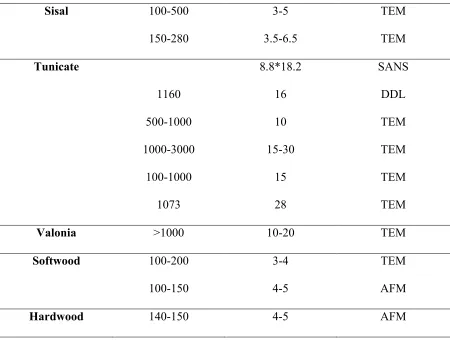
CNC is highly crystalline (up to ca. 91 % CrI)[26] and have a high aspect ratio[27]. The size and degree of crystallinity of CNCs depend on the source of cellulose (Table 1.1)[28]. CrI is defined here as crystallinity index to expresses the relative amounts of crystalline and non-crystalline components[29].
It has been well known that the crystals can form ordered nematic phases in electrolyte-free aqueous suspensions when the critical concentration is reached. The critical concentration is highly depending on the charge density and typically ranging between 1% and 10% (w/w)[28]. The formation of chiral nematic phase (isotropic to anisotropic equilibrium) is sensitive to the presence of electrolyte[28]. The chiral nematic phase of CNC has interesting optical, magnetic and piezoelectric properties.
Cellullose nanocrystal has a greater axial elastic modulus per density than Kevlar and its mechanical properties are competitive compared to other reinforcing agents (Table 1.2)[28, 30,
31]. Since Favier et al. reported that CNC reinforced the mechanical properties of polymer films
is a low cost, renewable, biodegradable and easily modified material. In recent years, CNC has been incorporated into a wide range of water-soluble and non-polar polymer matrices. The reported work of CNC incorporation in water-soluble polymer include poly(vinyl alcohol)[33], poly(ethylene oxide)[34] and poly(styrene-co-butyl acrylate)[35]. The non-polar polymers include poly(ε-caprolactone)[36, 37],polypropylene[38, 39] and others.
Table 1.1 Size of CNCs obtained from various sources by different techniques[28]
Source Length (nm) Width (nm) Techniques
Bacterial 100-1000 10-50 TEM
100-1000 5-10*30-50 TEM
Cotton 100-150 5-10 TEM
70-170 ~7 TEM
200-300 8 TEM
255 15 DDL
150-210 5-11 AFM
Cotton linter 100-200 10-20 SEM
25-320 6-70 TEM
300-500 15-30 AFM
MCC 35-265 3-48 TEM
250-270 23 TEM
∼500 10 AFM
Ramie 150-250 6-8 TEM
Table 1.2 Continued
Sisal 100-500 3-5 TEM
150-280 3.5-6.5 TEM
Tunicate 8.8*18.2 SANS
1160 16 DDL
500-1000 10 TEM
1000-3000 15-30 TEM
100-1000 15 TEM
1073 28 TEM
Valonia >1000 10-20 TEM
Softwood 100-200 3-4 TEM
100-150 4-5 AFM
Table 1.3 Properties of CNCs and several other reinforcing agents[30]
Materials ρ,
g/cm3
Tensile strength, GPa
Young’s modulus, GPa
Kevlar-49 fiber 1.4 3.5 124-130
Carbon fiber 1.8 1.5-5.5 150-500
Steel wire 7.8 4.1 210
Clay nanoplatelets - - 170
Carbon nanotubes - 11-63 270-950
Boron - 2-8 250-360
CNCs 1.6 7.5-7.7 110-220
1.1.1.2 Nanofibrillated cellulose
Nanofibrillated cellulose (NFC), also term as cellulose nanofibril (CNF), refers to the cellulose fibers which have been fibrillated into cellulose microfibril unites. NFC can be produced by chemical or enzymatic treatment of cellulose fibrils, followed by mechanical disintegration [40, 41]. Bleached kraft pulp is the most used source for NFC production, followed by bleached sulfite pulp. Some other non-wood sources have been investigated to produce NFC, i.e., wheat straw and soy hulls [42], sisal [43] and bagasse [44]. Even though the material sources play an important role in the energy consumption, the material source seems not have significant effect on the final NFC properties.
there are three main technique are preferred to manufacture NFC: (a) homogenizer (b) microfluidizer and (c) grinder. For the (a) homogenizer system, the fibers are subjected to high mechanical shearing, combined with high pressure. In the (b) microfluidizer, the wood suspension is sent though an interaction chamber which consists of several microchannels which are used for the fibrillation process. The smaller size of the microchannel, the higher degree of fibrillation. In the (c) grinder, the pulp is sent though two grinding stones with countersense
rotation and imparts high shearing to the cellulosic materials. Some other methods have been
proposed to manufacture NFC, including cryo-crushing, refiners and extruders, however, none of
them are widely accepted and used.
In order to decrease the energy consumption, two pre-treatments are performed: enzymatic and
TEMPO pre-treatment. The enzymatic treatment can reduce the fiber length and increase the
content of fine materials. Moreover, the enzymatic pre-treatment can increase the disintegration of
cellulosic material by increasing its swelling in water. The TEMPO pre-treatment can selectively
convert the C6 primary hydroxyl group to carboxylate group. The modification of cellulose surface
is applied in order to reduce the strength of hydrogen bonds which link fibers together[45].
The diameter of these fibrils are less than 100 nm and can go as small as 4 nm [46]. The length of NFC ranges from 1 to several micrometers, leading to a high aspect ratio [45].
smooth films [52]. Orelma et al. found that surface functionalized NFC films can be used as a platform for immunoassays and diagnostics [53].
1.1.1.3 Drying methods of nanocelluloses
Four methods have been developed to dry nannocelluloses/microcelluloses suspensions, including oven drying, freeze drying, supercritical drying and spray drying[54].
Oven drying is conducted by exposing the nanocellulose suspensions in a conventional laboratory oven at 105°C with circulating air. The water evaporation undergoes three periods[55]: (1) the constant rate drying period, (2) the first falling rate drying period, and (3) the second falling rate drying period. In the constant rate drying period, the volume of nanocellulose suspension shrinks which is ascribe to the capillary forces as a function of water evaporation. The first falling rate drying period starts when the nanocellulose get exposed, and the water is mainly evaporated from cellulose surface. In this period, the capillary tension reaches a maximum value and vapor diffusion begins to take over. When the water transfer rate from suspension interior to the exposed surface becomes smaller than the water diffuse rate on the surface, the drying process falls into the second falling rate drying period. The drying is completely taking place insider the nanocellulose suspension. At this time, strong intermolecular hydrogen bonds develop to form a continuous fiber network and a relatively solid bulk material.
During the attempted dehydration of the CNC suspensions, complete replacement of the water in the suspension by using ethanol was not possible. Therefore, SCD was not applied to the CNC suspensions and no dry form of CNC was obtained. A possible reason for the poor ethanol dehydration in the CNC suspension might be attributed to the strong three-dimensional hydrogen bonding formed among the water molecules and cellulose nanocrystals.
Four steps are involved in supercritical drying process: (1) dehydration of nanocellulose suspension with ethanol, (2) replacement of ethanol with liquid CO2, (3) pressurization and heating of the liquid CO2 and the cellulose mixture to the supercritical conditions, and (4) slow
decompression of the supercritical CO2 to atmospheric pressure[57].
Figure 1.5 The mechanism of spray drying process for nanocelluloses[54].
The morphological properties of the dried nanocelluloses are dependent on the particular drying method and the starting materials. Spray drying was claimed to be the technically suited method to dry nanocelluloses since the nanocellulose particle size ranges from nano to micron were obtained[59]. Supercritical drying and freeze drying created highly networked structures
of cellulose agglomerates with multi-scalar dimensions including the nanoscale. The highly-networked dried nanocellulose may hinder the application of the products in particular composites since the difficulties in dispersion would remain as a barrier in conventional thermoplastic compounding[54].
residue, whereas the crystal structure and crystallinity remained during the drying treatments[60].
1.1.2 Hemicellulose
Cellulose has a linear structure with glucose units, whereas hemicelluloses are heteropolysaccharides that may contain side groups or side chains. The degree of polymerization of hemicellulose is arounf 50-300, lower than of cellulose. The building blocks in hemicelluloses are pentoses, hexoses, hexuronic acids and deoxy-hexoses (Fig. 1.6). In the current stage of knowledge, hemicelluloses can be divided into four general classes of structurally different polysaccharide types, i.e., (a) xylans, (b) mannans, (c) β-glucans with mixed linkage, and (d) xyloglucans.
Figure 1.6 The sugar units of hemicelluloses. Glc: glucose, Man: mannose, Gal: galactose, Xyl: xylose, Ara: arabinose, Rha: rhamnose, Fuc: fucose, f: furanose, p: pyranose, U: uronic acid[5].
1.1.3 Lignin
Lignin is the second most abundant organic substance in the plant world next to cellulose. It exists in the wood tissues and it binds cellulose together in cell walls, fills in the space between the cells and provides the rigidity to wood structure[63]. The amounts of lignin differ greatly among wood species. In addition, the distribution of lignin in different parts also varies[64].
Lignin is a complex, branched aromatic polymer. Since its three building units, trans-coniferyl alcohol, trans-sinapyl alcohol and trans-p-coumaryl alcohol (Fig. 1.7), are not linked together in a specific systematic order, lignin is an amorphous three-dimensional polymer.
Figure 1.7 The building units of lignin[63]. 1.2 SURFACE MODIFICATOIN
ultrathin polymer coatings consisting of polymer chains with one chain end tethered to the interface[65].
1.2.1 “Grafting onto” and “grafting from”
The “grafting onto” method requires the pre-synthesized polymer chains to react with those hydroxyl groups. However, steric hindrance and blocking of reactive sites by the already grafted chains can prevent optimal reaction, because the polymer chains must diffuse though the grafted brushes and reach the reactive sites. The “grafting onto” method is therefore not expected to have high density of polymer brushes.
To increase the grafting density, the “grafting from” method can be employed. In this method, polymer chains are formed by in situ polymerization triggered by the immobilized initiators. The molecular growth can be achieved by conventional radical, ionic and ring-opening polymerizations. The “grafting from” method allows accurate control of brush thickness, composition and architecture[65].
1.2.2 Chemisorption
The oriented hydrophobic tails can lower the surface free energy of cellulose[68]. The use of poly(propylene-graft-maleic anhydride) (MAPP) as coupling agent also received great attention. The reaction mechanism between MAPP and cellulose is similar to ASA and cellulose. The similarity of PP and MAPP enable the co-crystallization which is desired for the cohesive bonding[67]. Stearic acid (SA) has also been used to treat the surface of polar fillers[69].
Figure 1.8 Schematic for surface modification: (A) physisorption (“grafting onto” method); (B) chemisorption (“grafting onto” method); (C) “grafting from” method[65].
1.2.3 Physisorption
protruding into aqueous environment, and forming brush-like structure[72]. At lower pH, β-casein adsorbs more and the layer becomes thicker. The tail extension decreases 6 lattice units if the pH is reduced from 7 to 5.5, while the hydrophobic parts are less sensitive to pH[72].
Soybean (SP) proteins are utilized in paper coating and sizing section in paper industries. Twenty proteins and 7 polypeptides are found to increase the wet strength of paper[73]. Soybean proteins comprise more than 50% of raw bean weight[74]. Soybean proteins have one fraction without biological activity, which is the so-called storage proteins[75]. They are by-products of the soybean oil industry, and are utilized as animal feed. With the demand for soybean oil, a considerable number of (residual) proteins are produced. Due to their good availability and low price, storage proteins stimulated the development of new functional material [76].
1.3 NONWOVEN MANFACTURING PROCESS
A definition for nonwoven from ISO 9092 (2011) is “A structure of fibers, continuous filaments, or chopped yarns of any nature of origin that have been formed into a web by any means, and bonded together by any means with the exception of weaving or knitting, and wet milling”. Nonwoven fabric manufacturing is composed of four sections: raw materials preparation, web formation, web bonding and finishing.
1.3.1 Dry-laid technology
Web can be produced from staple fibers using dry-laid technology via carding or air-lay process.
The staple tufts require to be opened, blended and cleaned before being fed to carding. The fibers are disentangled and combed during carding process. The stationary flat card is typical for short fibers, while long staple fibers are fit roller top card (Fig. 1.9). Since the fibers are oriented in machine direction, cross-lapping process is used to randomize the orientation distribution of fibers. Cross-lapping can also help to increase the basis weight and improve the uniformity of web[78-80].
Air-lay is another option to form web using staple fibers as raw materials. It can accommodate almost any materials, including wood pulp, natural fibers, manufactured fibers, recycled fibers and powders. The fibers are suspended in air and deposited on a forming wire conveyor (Fig. 1.10) or on a rotating perforated cylinder (Fig. 1.11). The vacuum under the forming wire and perforated cylinder has the function of removing the dusty air and very short fibers[78-80].
Figure 1.10 Web forming on the forming wire conveyor[79].
1.3.2 Wet-laid technology
Wet-laid process is adopted and modified from papermaking (Fig. 1.12). Comprared to paper, the wet-laid fabric has more open structure. Wet-laid line can process any natural or synthetic fibers. Those fibers are longer, stronger and inerter than natural fibers processed in papermaking line. Fiber dispersion is important, since fiber aggregates (i.e., logs and ropes) will otherwise appear on final fabric. The fibers are suspended in water and followed with laying down on the belt, dewatering and drying[78-80].
Figure 1.12 Illustration of nonwoven wet-laid web formation[79].
1.3.3 Spun-laid technology
Materbatch with certain filler content is necessary during fiber extrusion, since it has been proved that blending masterbatch with neat polymer during fiber extrusion is much easier tha direct blending filler with neat polymer[81]. The masterbarch is obtained by pre-blending filler with neat polymer at a certain ratio using an extruder. Compared to the single-screw extruder, the double-screw extruder is believed to be more efficient to get a uniform mixing.
polymer, maleic anhydride grafted polypropylene (MAPP) is always being used as compatibilizer to increase the interaction between PP and some other fillers. However, there is a critical level for individual maleated PP to be incorporated into the nanocomposite. High loading of MAPP is detrimental to the mechanical properties, and low loading cannot reach the desirable degree of polymer/MMT interaction[85]. As a result, the relationship between the chemistry of compatibilizers, the material feeding sequences and the design of compounding process should be coupled, because they all might affect the dispersion behavor and the final properties of the nanocomposites.
1.3.3.1 Spunbond process
Figure 1.13 Schematic of a typical spunbond process with a belt collector[87].
Depending on the type of thermoplastic, some preparations are required. For instance, Polyethylene terephthalate (PET) and polyaimides are both required to be dried and crystallized before extrusion. Additives are used in some instances targeting to promote the process (i.e., anoxident, antistatic agent and plasticizer) and provide some necessary function to the product (i.e., color concentrate, flame retardant and UV stabilizer). Most spunbond grade thermoplastics are already formulated with some essential effectives related to processibility. The viscosity of additive should be compatible with polymer viscosity[78-80].
bonded together to form a strong fabric using special bonding technology depending on the consumption and cost of energy, and the requirement for the final product[78-80].
1.3.3.2 Meltblown process
Meltblown is also a one-step process which converts polymer pellets or chips into finished fabric in an integrated step. Unlike spunbond fibers, the meltblown product has some discrete filaments other than continuous filaments, and the fibers are finer (2-8 micrometer). Meltblown process attributes to the production of fine fibers for the applications where high surface area and pores are required [78-80, 88].
The raw materials are required to have low viscosity to permit the attenuation of the molten polymer by hot air. The polymers is firstly extruded through fine capillaries, followed with the attenuation of polymer melts using hot air with high velocity. The molten polymer is then cooled down to form fine fibers by turbulent ambient air. The formed fibers are finally deposited on collector for future bonding and winding[78-80, 88].
1.4 POLYMER BLENDS
The Gibb’s free energy of mixing is the basic thermodynamic relationship governing the mixing of dissimilar polymer. Polymer blends are macroscopically homogeneous mixture of two or more different species of polymers[89]:
ΔGm = ΔHm − TΔSm
where ΔGm is the free mixing energy; ΔHm is the mixing enthalpy; T is the temperature and ΔSm is the mixing entropy.
The thermodynamic condition of miscibility is same as that of a molecular mixture in which the free mixing energy must be lower than zero (ΔGm<0). In the case of material with low molar mass, an increase in temperature usually leads to an increase in TΔSm and the ΔGm is therefore more negative leading to better miscibility. However, this is not always the case in polymer-polymer mixtures.
It is possible to employ the Flory-Huggins theory which is developed initially for polymer-solvent mixtures, to describe the thermodynamic behaviors of polymer blends.
ΔGm = RT (n1 ∗ lnФ1 + n2 ∗ lnФ2 + n1 ∗ lnФ2 ∗ χ12)
Ф1 = 71 ∗ 81
(71 ∗ 81 + 72 ∗ 82)
Ф2 = 72 ∗ 82
(71 ∗ 81 + 72 ∗ 82)
According to Flory and Huggins, the mixing enthalpy and entropy can be expressed by following formulas:
ΔHm = RTχ12 Ф1 Ф2
where R is the gas constant; χ12 is the Flory-Huggins parameter describing the interaction
between polymer polymer 1 and 2; Ф1 and Ф2 are the volume fractions and n1 and n2 are the number of moles of polymer 1 and 2, respectively.
The interaction parameter χ12 has a temperature dependence. An increase of temperature
result in ΔGm becoming less negative thus decreasing the miscibility of the polymers.
χ = a +; <
In Flory and Huggins, the first two terms on the right side are the combinational mixing entropy and the third term is represents enthalpy. In the case of solvent-solvent or polymer-solvent mixtures, the combinational entropy is large and negative, since Ф1 and Ф2 are fractions. Hence an increase in temperature leads to more negative ΔGm and better mixcibility. However, in the case of polymer0polymer mixtures, n1 and n2 are relatively small and the combinational entropy is therefore less important[90]. Hence the enthalpic part usually
dominates the mixing behavior. It can be either positive or negative depending on the compatibility of the two polymers. Since most polymers are incompatible with each other, their interaction parameter is large and the enthalpy of mixing is positive.
The calculation of the free mixing energy based on the Flory-Huggins theory does not account any intermolecular interactions which can range from purely dispersive forces to very strong hydrogen bonds. Coleman et al.[91] developed a modified version of the Flory-Huggins equation in which a free energy term (ΔGH) is added to original equation to take into account
the presence of strong, specific intermolecular interactions such as hydrogen bonding.
ΔGm = RTχ12 Ф1 Ф2 + RT Ф1
71lnФ1 + Ф2
1.5 COMPOSITE PRODUCTION 1.5.1 Solvent casting
Most of the nanofiber reinforced polymer composites fabricated through polymer solution or polymer dispersion (latex) due to preserving filler dispersion in liquid medium[59]. Solvent casting can be considered as an efficient method for fabrication of nanocomposites in laboratory scale. This process provides more uniform and stable dispersion of filler in polymer matrix comparing to melt extrusion technique, but it is an expensive method and consists of more
complicated process and use of undesirable chemicals and toxic solvents.
1.5.2 Melt compounding
Melt compounding techniques, such as extrusion or injection molding, are commonly used to process thermoplastic polymers. Extrusion is a high volume manufacturing process in which the polymer is melt and transported via screws. Extrusion product has a fixed cross-section profile since it is pushed through a desired die. For the injection molding, the molten polymer is forced into a mold cavity by using a ram or screw-type plunger. Due to the absence of chemical reactions and organic solvent, the melt compounding process is therefore much less expensive and also more environmentally friendly. However, this conventional processing technique was seldom reported to be used to produce nanocellulose reinforced polymer nanocomposites. This is ascribe to the intrinsic hydrophilicity of nanocellulose which will induce the irreversible agglomeration during drying and aggregation in non-polar matrix because of the formation of extra hydrogen bonds between those nanoparticles[59].
stability is mainly contributed to the introduction of sulfate groups during the acid hydrolysis process.
1.6 REINFORCEMENT OF NANOCELLULOSES IN BIOCOMPOSITES
During recent years, plenty of effort has been devoted to biocomposites. Polymers from bioresources have attracted an increasing amount of attention over the last two decades, predominantly due to the environmental concerns and the finite petroleum source. In order to overcome the environment and sustainability problems, remarkable achievements have been observed in green chemistry in terms of the investigation of biocomposites[1, 2]. Bionanocomposites are a family of materials consisting fillers with at least one dimension smaller than 100 nm[92]. The filler can be a fiber, platelet or particle. The development of materials derived from natural resources has a growing trend in the drive to protect our environment. Cellulose is the most abundant, biodegradable and natural polymer, derived from bioresouces, i.e., wood, cotton and corn straw as well as some sea animals. The intrinsic properties of cellulose endow it to be a very promising polymer for the production of environmentally-friendly biocomposites.
aspect ratio, filler-filler interaction and their orientation within the polymer matrix. Percolation threshold (V) if cellulose nanocrystals is determined using the following equation[59]. Stiffness of percolation network depends on the cellulosic filler and strength of interfibrillar interactions. It is shown that the filler with higher aspect ratio provides stiffer percolating network with lower filler volume fraction[59].
= = 0.7 A/C 1.6.1 Effects of fillers/reinforcements-functions
Traditionally, fillers are considered to be additives, which can only increase the polymer modulus to a little degree due to their unfavourable geometrical features, surface area or surface chemical composition[93], while the polymer strength remain unchanged or even decreased. The major contribution of traditional fillers were to lower the cost of the product by replacing the expensive polymer; other advantages were to increase thermal conductivity and decrease the rejected parts due to warpage, in this case, the molding cycles were facilitated. Some other properties of polymer may be changed due to the incorporation of fillers, i.e., melt viscosity, mold shrinkage and thermal expansion. Fibrous filler would increase the melt viscosity and the inorganic fillers would reduce the mold shrinkage and thermal expansion[93]. The term of reinforcing filler has been used to describe the discontinuous additives, the shape, form and surface chemistry of which can be modified to be incorporated into polymer matrix. The function of the reinforcing filler is to improve the mechanical properties of the polymer, especially strength.
The ratio of surface area to volume is a widely used parameter to evaluate the effectiveness of a reinforcing filler. The ratio is required to be as high as possible for effective reinforcement[93]. Since the reinforcing filler may have different chemical structure and properties with the polymer matrix, the aims of reinforcing filler development and material surface modification are to increase the aspect ratio of the filler particles and increase the interfacial adhesion with the polymer matrix. The surface modification may not only enhance or optimize the reinforcing function of the filler, but may also introduce some new functions.
1.6.2 Interaction between polymer and filler
Filler particles tend to form aggregates by cohesion. The presence of aggregates in fibers affects the fiber structure and uniformity to a great extent. Weakness of fibers is mainly ascribe to the poor dispersion of fillers in polymer matrix during compounding, extruding, mixing and spinning.
some capillary pressure in the aggregate cluster. Adhesion force of liquid bridge can be calculated according the following equation:
D ∗= DE ∗ F ∗ 8
Where the F* is the mean adhesion force transmitted at a contact point, FH is the dimensionless
adhesion number, which can be calculated for axially symmetrical liquid bridge, γ is the durface tension of the liquid, and x is the mean particle size[94].
Filler size is very important to the mechanical properties of polymer composite. Dominkovics, et al., studied the effect of wood flour on the properties of PP composite[95]. It was demonstrated that the wood flour decreased the mechanical properties, probably due to the formation of big voids induced by the wood flour. The voids caused the catastrophic cracks of PP composite. However, the nanoscaled cellulosic fillers can highly improve mechanical properties of composite. Filler particles can be wetted by polymer melt/liquid which has lower surface tension than the filler surface tension. Young’s equation shows the relationship between the contact angle and surface tension.
FGH = FGI + FIH"JGK
LM = FGH + FIH − FGI = FIH(1 + "JGK) LM = FGH + FIH − FGI = FIH(1 + "JGK)
is to reduce the polar difference between filler and host polymer and minimize the surface tension[59].
The interaction at the interface of cellulosic filler and host polymer cannot be neglected. Filler interfacial tension, substrate interfacial tension, polarity and surface contamination as well as flaws on the surface are the main factors which affecting the adhesion between filler and host polymer.
1.6.3 Kinetics of aggregation formation
Aggregation starts from small molecules or crystals in solutions, in which intermolecular forces, including Brownian motion, London dispersion and electrostatic force, drive small molecules or crystals to agglomerate into clusters. There are three growth kinetics for the aggregate formation: (1) Particle-cluster aggregation (PCA). During the formation process, the small particle stick on to another particle in the growing cluster. The second kinetic is called (2) cluster-cluster aggregation (CCA). It is different from the PCA, since the aggregated are formed by the combination of clusters. (3) The diffusion limited aggregation is the third kinetic[96, 97]. The particle is assumed to undergo a random walk until it hit the particle seed and sticks on it, the second particle is then released, and this process repeats until the a larger aggregate has been formed which containing N=O(104) particles.
Based on the kinetics of aggregation, an equation was development to describe the aggregation rate:
R=D/F
Where D is the diffusion rate and F is the deposition flux.
The fractal dimension df is used to quantitatively characterize the cluster. The df is a direct
increases. If M(R) is the cluster mass within a Pythagorean distance R of a cluster point, and ρ(R) = M(R)/ Rd is the density, then one writes:
M(R) ~ Rdf ρ(R) ~ Rdf-d
1.6.4 Effect of microfibrillated lignocellulose on polymers
Due to the abundance of accessible hydroyxyl groups, cellulose has a highly polar surface. Dispersion in water and water-soluble polymers can therefore be achieved easily. By contrast, dispersion of cellulose in non-polar solvent or polymers are very challenging. Surface modification or compaitibilizer is required to establish the compatibility between cellulose and hydrophobic polymers, however additional cost is induced.
Lignin is the second most abundant natural after cellulose, which contains both of polar and non-polar groups. Lee and Luner found that the sessile contact angle water made with lignin was about 60°[98]. Laschimke concluded that milled wood lignin as well as lignin from the organocell process was wettable, even though the contact angle in these measurements was initially around 80°. However, the contact angle dropped to 63° which is far away from 90° as a function of time[99]. Lignin is normally considered to be a hydrophobic polymer, but according to the strictest definition of a water contact angle greater than 90°[100], lignin is not hydrophobic and water may be considered to be a partially wetting liquid on a lignin surface. This also supports the long-term belief that some fractions of lignin provide water-proof aid in the water transport of plants. Although the total surface free energy of isolated lignin is comparable with cellulose, the dispersive intermolecular forces arising from the higher percentage of non-polar moieties are more pronounced compared to cellulose[101].
could feature a similar mode of action as conventional compatibilizer in polymer composites by providing polar and non-polar moieties[103]. AFM adhesion force measurement revealed variability of polarity of microfibrillated lignocellulose. Domains of the moieties with higher polarity and lower polarity than microfibrillated cellulose were both found in microfibrillated lignocellulose[103]. More homogeneous distribution of fibrils in polycaprolactone and polystyrene was achieved by loading microfibrillated lignocellulose than microfibrillated cellulose. Compared to microfibrillated cellulose, significantly more efficient mechanical reinforcement was observed after the addition of microfibrillated lignocellulose[103]. Good fiber spinning was observed by Kubo and Kadla for both lignin/PET and lignin/PP systems, however, only the PP with a molten viscosity comparable to the spinning temperature was able to be continuously spun into fibers[104]. The lignin-containing nanocelluloses were found to exhibite the hydrophobic property to some extent compared to pure cellulose, and the authors believed this result indicates the NFC could have good compatibility to polymer matrix while making composites[105]. The addition of few content of lignin to plant fiber-polymer composites was discovered to have positive effects on their mechanical performance, including PP[106], PLA[107] and epoxy[108]. Kraft pulp and thermomechanical pulp pretreated in sulfuric acid yielded microfibrillated material was found to slightly improved the tensile-strength performance of PLA, however the improvement induced by lignin-containing cellulose material was not as much as lignin-free cellulose material[109].
1.6.5 Reinforcement of nanocelluloses in hydrophobic polymers
recent years, nanocellulose has been tremendously incorporated into a wide range of polymer matrices, including poly(ε-caprolactone)[36, 37], poly(vinyl alcohol)[33], polypropylene[38, 39] and others. The enhancement of the increased mechanical behavior was proposed to be the result of strong network form by interaction of nanocelluloses and nanocellulose with polymer.
Cellulose nanocrystals are great reinforcing fillers in bionanocomposites as a combination of their high surface area and unique morphology as well as good mechanical response to stress. Habibi and his colleagues incorporated CNC into PCL matrix to improve the tensile properties of the bionanocomposite[110]. In their work, the CNCs were modified by attaching PCL via ring-opening polymerization in order to improve the compatibility between the hydrophobic PCL matrix and the hydrophilic CNCs in bionanocomposites. From their work, the addition of PCL-grafted CNCs into PCL were proved to improve considerably the Yong’s modulus from 230.7 MPa to 52.0 MPa of the solvent casted solid bionanocomposite film.
The reinforcement of nanocelluloses in poly(ε-caprolactone) was also investigated by Mi and his colleagues[37]. In Mi’s work, both of solid and microcellular samples were studied. The CNCs were compounded with PCL directly using a twin-screw extruder. Microcellular injection molding was used to produce the foamed bionanocomposites. It was proved that CNCs effectively improved the tensile moduli and storage moduli of both solid and foamed PCL composite.
![Figure 1.2 Cellulose structure. Stereochemical (a), abbreviated (b), Haworth perspective (c), and Mills’ perspective (d) formulas[5]](https://thumb-us.123doks.com/thumbv2/123dok_us/1597340.1197210/32.612.180.455.73.380/cellulose-structure-stereochemical-abbreviated-haworth-perspective-perspective-formulas.webp)
![Figure 1.3 Structures of cellulose Iβ, Iα, II, and IIII illustrating differences in chain tilt, packing and hydrogen bonding[8]](https://thumb-us.123doks.com/thumbv2/123dok_us/1597340.1197210/33.612.96.521.73.287/figure-structures-cellulose-illustrating-differences-packing-hydrogen-bonding.webp)
![Table 1.1 Size of CNCs obtained from various sources by different techniques[28]](https://thumb-us.123doks.com/thumbv2/123dok_us/1597340.1197210/37.612.89.539.230.681/table-size-cncs-obtained-various-sources-different-techniques.webp)
![Table 1.3 Properties of CNCs and several other reinforcing agents[30]](https://thumb-us.123doks.com/thumbv2/123dok_us/1597340.1197210/39.612.113.543.95.347/table-properties-cncs-reinforcing-agents.webp)
![Figure 1.5 The mechanism of spray drying process for nanocelluloses[54].](https://thumb-us.123doks.com/thumbv2/123dok_us/1597340.1197210/43.612.92.529.71.374/figure-mechanism-spray-drying-process-nanocelluloses.webp)
![Figure 1.6 The sugar units of hemicelluloses. Glc: glucose, Man: mannose, Gal: galactose, Xyl: xylose, Ara: arabinose, Rha: rhamnose, Fuc: fucose, f: furanose, p: pyranose, U: uronic acid[5]](https://thumb-us.123doks.com/thumbv2/123dok_us/1597340.1197210/45.612.200.433.74.498/figure-hemicelluloses-glucose-galactose-arabinose-rhamnose-furanose-pyranose.webp)
![Figure 1.8 Schematic for surface modification: (A) physisorption (“grafting onto” method); (B) chemisorption (“grafting onto” method); (C) “grafting from” method[65]](https://thumb-us.123doks.com/thumbv2/123dok_us/1597340.1197210/48.612.146.483.212.512/figure-schematic-modification-physisorption-grafting-chemisorption-grafting-grafting.webp)