R E S E A R C H
Open Access
A traffic flow-oriented routing protocol for
VANETs
Irshad A Abbasi
1, Babar Nazir
2*, Aftab Abbasi
3, Sardar M Bilal
4and Sajjad A Madani
2Abstract
This paper presents a novel position-based routing protocol for vehicular ad hoc networks (VANETs) to enhance traffic safety and traffic organization and facilitate driving through a smart transportation system. The protocol is referred to as the traffic flow-oriented routing (TFOR) protocol for VANETs. It considers a real-time urban scenario with multi-lane and bi-directional roads. It chooses junction optimally considering vehicular traffic flows to accomplish robust routing paths and thereby forwarding the data packets. The new junction selection mechanism and routing between the junctions is based on two-hop neighbor information, which increases packet-delivery ratio and decreases end-to-end delay. We designed, implemented, and compared TFOR against existing routing protocols of VANETs (greedy-perimeter stateless routing (GPSR), geographic source routing (GSR), and enhanced greedy traffic-aware routing (E-GyTAR)). Simulation outcomes in urban scenarios show that TFOR minimizes average end-to-end delay and routing overhead by on average 15.3% and 19.5%, respectively, compared to GPSR. It reduces routing overhead up to 17% compared to GSR. TFOR maximizes packet-delivery ratio on an average of 17.5%, 10.7%, and 7.2% compared to GPSR, GSR, and E-GyTAR, respectively.
Keywords:Traffic flow; Traffic organization; Vehicular ad hoc network (VANET); Position-based routing
1. Introduction
Recently, immense increase in the number of automobiles on the road made driving difficult and unsafe. Roads are routinely replete with vehicles, and therefore, safe-separation distance and sensible speeds do not seemed to be valued anymore. For instance, according to NHTSA (National Highway Traffic Safety Administration) [1] in 2006, there were an estimated 42,642 traffic-related casualties. The per-centage (2%) of casualties in 2005 was even higher than that of casualties in 2006. There are some advanced active and passive vehicle safety-related devices such as airbags, crum-ble zones, and anti-lock brakes invented to reduce causali-ties. The number of casualties in spite of all these latest devices has remained more than 40,000 per year for the last 15 years. Accidents do happen, but sight cannot be lost of the concept of road safety. Top car manufacturers and na-tionwide government agencies are determined to design so-lutions that assist drivers in anticipating danger and avoiding bad traffic zones. One such effort is the exploitation
of wireless technology, to direct traffic issues, in the form of wireless access for vehicular environment (WAVE) devoted to the vehicular ad hoc networks (VANETs) [2-4]. The aim of WAVE is to overcome traffic issues and make driv-ing efficient by givdriv-ing timely guidance to drivers and vehi-cles that are not available through driver observations and independent sensors [1,5-7].
Vehicular communication is possible through either vehicle to vehicle (V2V) or vehicle to infrastructure (V2I) or both. The goal of VANETs is to build an intelligent transportation system (ITS) [8]. It supports a wide variety of applications including prevention of accidents, traffic flow control mechanisms, information services, real-time alternate route computations, and provision of Internet ccess to the vehicles on motion [4,8-13]. Vehicular commu-nication is an offshoot of mobile ad hoc network (MANET) [9,12,14]. VANETs have certain characteristics that change them from MANETs. In VANETs, >high-speed vehicular nodes have intermittent connectivity and they frequently change the network topologies. Physical factors restrict node movements and network topologies. The movement of vehicles is along roadways, and their mobility is re-strained by traffic policies, such as traffic light signals, * Correspondence:[email protected]
2
Department of Computer Science, COMSATS Institute of Information Technology (CIIT), Abbotabad 22060, Pakistan
Full list of author information is available at the end of the article
© 2014 Abbasi et al.; licensee Springer. This is an Open Access article distributed under the terms of the Creative Commons Attribution License (http://creativecommons.org/licenses/by/4.0), which permits unrestricted use, distribution, and reproduction in any medium, provided the original work is properly credited.
speed constraints, and road/traffic conditions. Power expenditure is not a vital concern in vehicular nodes, as vehicles can generate enough power to run the commu-nication devices. In contrast, MANET's nodes are char-acterized by limited storage capacity, restricted battery power, low processing, and random movements with unpredictable mobility patterns [8,9,12,13].
This work realizes the potential of VANETs to enhance traffic safety and traffic organization and to facilitate driv-ing through a smart transportation system. In this work, we explored routing features of VANETs. We analyzed the previous routing literatures in VANETs. We have pre-sented their contribution and limitations. By using the unique characteristics of VANETs, we have developed a novel position-based routing protocol called traffic flow-oriented routing (TFOR) protocol for VANET multi-lane roads. It considers the vehicle's position, direction, and speed to decide the junction and dispatch the data packets. It consists of two mechanisms: (1) new junction selection mechanism and (2) routing based on two-hop neighbor information. The new junction selection mech-anism determines the directional and non-directional traf-fic flows based on real-time traftraf-fic in city environment. Determination of these flows provides shortest rich-density routing paths, which increase packet-delivery ratio and decrease end-to-end delay. We have also proved that forwarding, based on two-hop neighbor information, is a better choice than one-hop neighbor information, which also reduces the end-to-end delay and make routing more efficient. TFOR uses road topology and traffic density for efficient relaying of data in the network. It is useful for both delay-sensitive (like accident alerts, on-vehicle chat) and delay-tolerant (like infotainment) applications. The major contributions of this manuscript are as follows:
1. We provide a brief technical survey to analyze, compare, and present limitations of existing position-based routing protocols in VANETs. 2. We propose a novel position-based routing
algorithm with new concepts of directional routing and non-directional routing to rout the packet through a shortest rich-density city road to increase packet-delivery ratio and decrease end-to-end delay and routing overhead.
3. We propose a forwarding technique based on two-hop neighbor information and its importance in the reduction of end-to-end delay to obtain optimum performance.
4. We implement, analyze, and compare the behavior of our approach with existing approaches
(greedy-perimeter stateless routing (GPSR), geographic source routing (GSR), and enhanced greedy traffic-aware routing (E-GyTAR)) using VanetMobiSim and Glomosim simulators.
The rest of the paper is organized as follows. Section 2 describes the existing routing techniques along with their limitations. It also elaborates the motivation of the research work. Section 3 illustrates the proposed routing strategy. Analysis of the data and simulation outcomes are presented in Section 4. Finally, conclusions are presented in Section 5.
2. Related work
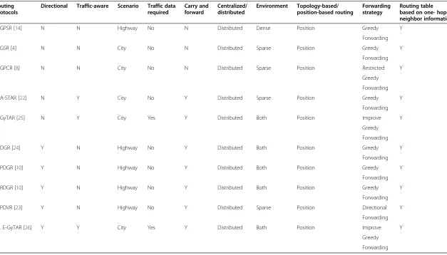
The available routing protocols in vehicular communication networks are broadly categorized into topology-based and position-based routing. The topology-based routing tech-niques can be reactive (on-demand), proactive (table-driven), and hybrid. On-demand routing protocols (e.g., DSR [15], AODV [16]) maintain only those routing paths that are currently in use. While table-driven routing proto-cols (e.g., OLSR [17,18]) maintain all the available paths in the network topology. The maintenance of routing paths affects the performance of protocols in a highly dynamic network [4,8,9,13,14]. In position-based routing protocols, each vehicle contains a GPS receiver or other positioning abilities so that the vehicular nodes can have precise know-ledge of their geological positions, movement directions, and speed. The location of destination node can be found using location services (e.g., HLS [19], GLS [20], and RLS [21]). There is no need of path maintenance [4,8,11,22] as each node has to memorize its one-hop neighbors through beaconing. These characteristics of position-based approach motivate us to focus on position-position-based routing for dealing the routing-related issues in VANETs. The existing position-based routing protocols are cate-gorized as directional and non-directional. As the name suggests, the directional routing protocols [10,23,24] focus on the direction of vehicles while routing the packets towards destination. The non-directional rout-ing protocols [4,8,11,14,22,25] do not focus on the dir-ection of the vehicles while routing. Examples of both the categories are listed in Table 1.
Table 1 VANET routing protocols Routing
protocols
Directional Traffic-aware Scenario Traffic data required
Carry and forward
Centralized/ distributed
Environment Topology-based/ position-based routing
Forwarding strategy
Routing table based on one- hop neighbor information
1. GPSR [14] N N Highway No N Distributed Dense Position Greedy Y
Forwarding
2. GSR [4] N N City No N Distributed Sparse Position Greedy Y
Forwarding
3. GPCR [8] N N City No N Distributed Sparse Position Restricted Y
Greedy
Forwarding
4. A-STAR [22] N Y City No Y Distributed Sparse Position Greedy Y
Forwarding
5. GyTAR [25] N Y City Yes Y Distributed Both Position Improve Y
Greedy
Forwarding
6. DGR [24] Y N Highway No Y Distributed Both Position Greedy Y
Forwarding
7. PDGR [10] Y N Highway No Y Distributed Both Position Greedy Y
Forwarding
8. RDGR [10] Y N Highway No Y Distributed Both Position Greedy Y
Forwarding
9. PDVR [23] Y N Highway No Y Distributed Sparse Position Directional Y
Forwarding
10. E-GyTAR [26] Y Y City Yes Y Distributed Both Position Improve Y
Greedy
Forwarding
Abbasi
et
al.
EURASIP
Journal
on
Wireless
Commun
ications
and
Networking
2014,
2014
:121
Page
3
o
f
1
4
http://jwcn
.eurasipjourna
ls.com/co
ntent/2014/1/
graph planarization fails in city scenarios and may cause partitioning of the network due to obstacles. Last but not the least, the fact is that GPSR is not a traffic-aware routing protocol [22].
One of the first attempts to handle the routing issues in city scenarios was the geographic source routing (GSR) [4] which employs the position-based knowledge with the topo-logical knowledge of the network. It runs Dijkstra's algorithm to locate the shortest route connecting the source and the destination. GSR computes a sequence of junctions based on the shortest route from source to destination using a street map that packets must have to traverse. It employs greedy forwarding to dispatch the data packets from source to target node. The greedy forwarding approach, as already stated, has the tendency to stick onto a local maximum. In this, eventu-ality, GSR uses a carry-and-forward approach as a recovery strategy. This protocol does not consider the number of ve-hicles between the junctions before forwarding packet. End-to-end connection is difficult in case of low traffic density along a preselected path [25]. It degrades the performance of GSR. In addition, it is not a traffic-aware routing protocol.
As against GSR, the greedy-perimeter coordinator rout-ing (GPCR) [8] is a map-independent routrout-ing technique. It includes restricted greedy forwarding and repair strategy. Restricted greedy forwarding prefers to choose the coordin-ator (the node on a junction) over a non-coordincoordin-ator node when deciding the next hop, even if the former is not the geographically nearest node to destination. The routing decision is, thus, made at the coordinator node that decides the street the packet should follow next. The repair strategy overcomes the local optimum problem. It consists of a per-imeter mode without any graph planarization phase. It is assumed that the graph planarization is natural in a city environment. So, there is no need of computing graph pla-narization, because it may cause a partitioning in the net-work. Similar to GSR, the GPCR neglects low traffic density case. Furthermore, it is not a traffic-aware routing protocol.
The anchor-based street and traffic-aware routing (A-STAR) is a traffic-aware routing protocol [25], as opposed to GPSR and GSR. From these latter two protocols, A-STAR has two main peculiarities. Firstly, it uses a statically or dy-namically rated map for traffic awareness and uses these maps to identify paths having higher number of vehicles. Secondly, A-STAR has a new local recovery technique, con-sidered to be better than those of GSR and GPSR [22], for the packets got stuck in local maximum. The path selected by A-STAR on the basis of anchors may not be the shortest, due to which it may have higher end-to-end delay [4,24].
Designed for city environment, the greedy traffic-aware routing protocol (GyTAR) [25] selects the junctions dynamically as against the static approach of GSR and A-STAR. GyTAR exhibits three mechanisms: (i) a com-pletely decentralized scheme, named the infrastructure free traffic information system (IFTIS) [21], which estimates
traffic density between the junctions in the urban roads; (ii) a mechanism for dynamic junction selection, i.e., when deciding the next destination junction, the source vehicle, or an intermediate vehicle in a junction finds the position of the neighboring junctions using the map, which allo-cates a score to each neighboring junction assuming the curve metric distance to the destination and the traffic density; and the next junction is the one that has highest traffic density and closest to destination vehicle, (iii) which applies an improved greedy forwarding mechanism to forward the packet between the two involved junctions. The wrong junction selection mechanism compels the packet to get stuck onto local maximum, especially at low traffic density or when all the vehicles moved away from the destination on the selected street, which is its failure [26]. The directional routing protocols [4,8,11,14,22,25] focus on the direction of the vehicles while routing. The technical detail of these routing protocols is presented below. The main problem with the non-directional routing protocols is the routing loop formation while routing the packet, which may cause delay [10]. Sometimes, the packet is sent to a vehicle that is moving away from the destin-ation, resulting in packet loss.
Directional greedy routing protocol (DGR) [10] resolves the issues outlined above by taking into consideration the direction of the vehicle and assigns higher weight to the vehicle that is moving towards the destination. It uses a carry-and-forward approach when packets get stuck onto a local maximum and works well in a highway scenario.
Predictive directional greedy routing protocol (PDGR) is an extended version of DGR that employs a predictive compared to the latter which only takes into account the current neighbors while calculating the weighted score. PDGR determines the weighted score for the packet carrier, its present neighbors, and the possible expected neighbors in the very near future. It decides the next hop based on these weighted scores. The packet carrier obtains the infor-mation of possible future neighbor based on the two-hop neighbor information. This information is achieved through periodical sending of hello messages. The use of a predic-tion mechanism makes the PDGR outperform the DGR in terms of end-to-end delay and delivery ratio.
The reliable directional greedy routing protocol (RDGR) [27] minimizes link breaks, improves route reliability, and enhances packet-delivery ratio. In DGR and PDGR, the likelihood of packet loss increases if the neighbor node moving in the direction of destination has higher speed as compared to source node or intermediate forwarder node. RDGR enhances DGR by introducing the new metric of link stability. In RDGR, a source node or an intermediate forwarding node chooses the next neighbor node having a higher speed as well as a stable link.
selects stable and efficient route for routing packet to the destination based on two rules. First, the neighbor selected for forwarding packet should move in the same direction as the source or the intermediate packet-forwarding node. Secondly, its direction must be similar to that of the destination. PDVR may not work well in a city environment because of some obstacles. It is not a traffic-aware routing protocol.
The DGR, PDGR, and RDGR protocols take into account only the highway scenarios [27]. The enhanced greedy traffic-aware routing (E-GyTAR) protocol [26] selects a routing path by using an enhanced junction selection mechanism. In this mechanism, the vehicular node on the current intersection selects the next intersection consider-ing the number of vehicles that are movconsider-ing in the direc-tion of the destinadirec-tion. If there is completely an opposite flow of the vehicles and none is moving toward destin-ation, then it cannot select a routing path that may reduce packet-delivery ratio and enhance end-to-end delay.
In general, most of the above routing approaches are not traffic aware. As a result, they forward the packets along the city street where moving vehicles are absent. In such situ-ation, packets meet local optimum and are discarded. These problems can be solved by having a mechanism that pro-vides timely information about traffic on the city streets. Some of these routing protocols (like A-STAR, E-GyTAR) are traffic aware but they are unable to use real-time vehicu-lar traffic density properly. As a result, these are inefficient in routing. In between successive junction, most of the above routing protocols (GSR, GPSR, A-STAR, etc.) use simple greedy forwarding. However, simple greedy does not con-sider neighbors' speed and direction. In addition, it uses only one-hop neighbor information. Hence, it misses some suit-able candidate vehicles for packet forwarding.
We propose a routing protocol that presents a solution to the aforementioned problems. The protocol accomplishes robust routes within urban environment. The protocol envi-sioned to work well for different types of VANET appli-cations and ensure user connectivity. These appliappli-cations include road-safety services (like traffic flow control mechan-ism, issuing driving alerts like traffic jams, accident warnings, road's condition, etc.) and comfort services (like gas station location, Internet access, music downloading, games, etc.).
3. TFOR
3.1. Problem formulation
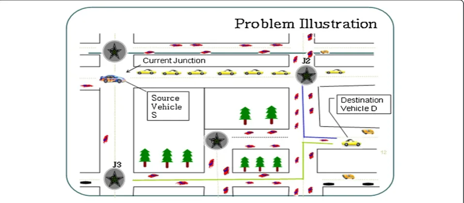
Figure 1 explains the scenario where E-GyTAR does not work well. The source vehicle S on the current junction wants to send data packets to the destination vehicle D. E-GyTAR selects the next neighbor junction considering the number of vehicles that are moving in the direction of the destination. In this scenario, no vehicle is moving towards the destination. All the vehicles are moving in the opposite direction of the destination but provide enough connectivity between S and D. E-GyTAR will not be able to select the junction J2 that is the closest junction to the des-tination. When the network is sparse, E-GyTAR performs well. However, when the numbers of vehicles are increased, a point comes where there is an adequate number of vehicles moving in an opposite direction and providing connectivity. Hence, E-GyTAR cannot find the geographic-ally closest path towards destination. This reduces packet-delivery ratio and enhances end-to-end delay. Therefore, we need a routing protocol that can select the routing paths/junctions based on directional density and otherwise. To tackle this issue, this paper suggests novel routing protocol called the traffic flow-oriented routing (TFOR) protocol.
Figure 1The problem scenario.
3.2. TFOR protocol
TFRO is a junction-based geographical routing protocol, competent to accomplish robust routes, considered to ex-hibit optimal performance in city scenarios. To attain this goal, it employs GPS to locate its own position. It uses grid location service (GLS) to acquire the position of destin-ation vehicle [20]. Every vehicle contains on-board naviga-tion system that finds out the locanaviga-tion of neighboring junctions and gives valuable city's street information with preloaded digital maps. It contains two mechanisms, viz., junction selection mechanism, and routing between junc-tions based on two-hop neighbor information.
3.2.1. The junction selection mechanism
Unlike E-GyTAR, which ignores non-directional density with respect to destination, TFOR selects the junctions dy-namically considering directional as well as non-directional flow of traffic density. The probability of occurrence of dir-ectional and non-dirdir-ectional traffic with respect to certain destinations in urban multi-lane road is equally likely. Therefore, directional and non-directional traffic is equally important for connectivity provision in VANETs. Ignoring a part of traffic density means neglecting connectivity. Compromise on connectivity degrades performance of ad hoc networks. The sending vehicular node in a junction uses a digital map to identify the location of neighboring junction. Location service makes the position of destination vehicle available. The sending vehicle after that determines the curvemetric distance from each neighbor junction to the destination vehicle. It uses algorithm 1 to assign a score to each neighbor junction. It chooses the junction with maximum score as a next destination junction. The chosen junction is the nearest to the destination vehicle. It has also the higher traffic density flow.
In algorithm 1, the following equation calculates the score that determines the next destination junction (N Dj).
score¼α 1−DpþβTD ð1Þ
where Dp=Dn /Dc decides the nearness of neighbor junction to the destination point.TD represents the total traffic density between the current junction (Cj) and the neighbor or next-candidate junction (N Cj), may be dir-ectional or non-dirdir-ectional. αand βare the weight fac-tors, such thatα+β= 1.
With equal importance of the two factors,αand βare both set to the value 0.5. Equation refeq:score suggests that the junction that has maximum score is chosen as the next destination junction. It is also geographically the nearest junction to the destination. As revealed in Figure 1, the proposed junction selection mechanism se-lects J2 instead of selecting J3 as the next destination junction because of the shortest distance and vehicular traffic density (directional or non-directional). After-wards, the TFOR junction selection mechanism chooses the best available shortest path to the destination consid-ering the vehicular density.
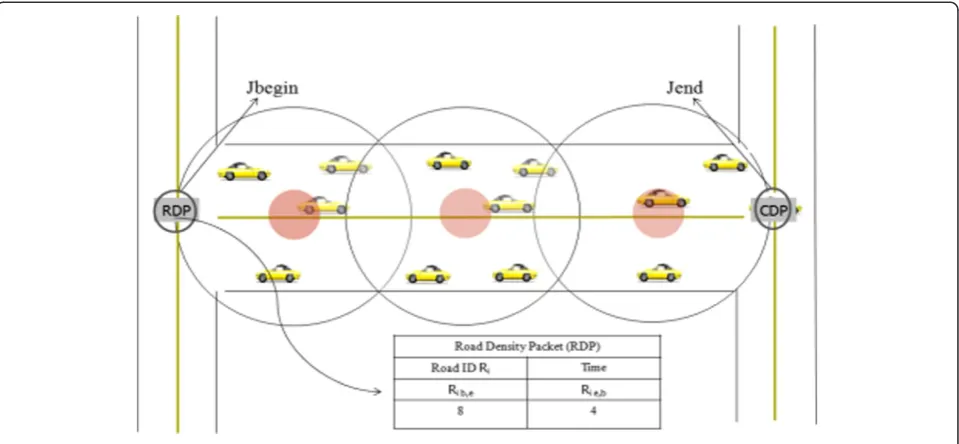
the closest to the center. The cell's center locations are being represented by tiny red circles called red zones. Only the group head generates and updates the cell density packet (CDP) by including the entire vehi-cles (the number of vehivehi-cles moving in the direction of destination and the number of vehicles moving op-posite to destination) present inside the cell. The ve-hicle, to depart the road, initiates the CDP. The CDP contains the road ID,the transmission time, the list of cell-center positions also called route anchors, the total density of a cell, and the directional as well as the non-directional density of the traffic within the cell. The CDP's data format is illustrated in Figure 3. Packets travel along the cell centers to reach other in-tersections. The whole density estimation method is shown in Figure 2.
Algorithm 2 enlightens the procedure of the packet-forwarding mechanism that follows the following steps.
The node F (forwarding vehicle) forwards the CDP packet between two junctions (i.e., Jend, Jbegin) of
the road section. It forwards the CDP packet from the end of junction Jendto the beginning of
junction Jbegin.
F may or may not be the group head. If it is a group head, then it will consult its neighbor table and update the CDP packet by adding the total density |V|itotalof the cell to which it belongs, directional
density |V|i↑, and the non-directional density |V|i↓.
F then forwards the CDP packet to the vehicular node that is nearest to the next anchor and so on. When the CDP packet reaches the group head of
the last anchor, it updates the packet and estimates the mean and variance related to the cell density. After that, estimated density will be forwarded to the destination junction.
If forwarding vehicle F has no appropriate neighbor vehicle closer to the next anchor, it will keep the CDP until it locates a vehicle that is nearest to the next anchor.
When the other junction (Jbegin) is reached, the CDP
is converted into a road density packet (RDP) and it is propagated around the junction.
Note that the number of vehicles within cell i moving from the start of junction to the end is represented by |V |i↑, whereas |V|i↓indicates the vehicles in cell i
mov-ing from end of junction to the start of junction.
Figure 2Road density packet.
Figure 3The cell density data packet format.
The RDP construction is explained in algorithm 3. In this algorithm, for a road i, if the forward direc-tion road density (Ri ↑ or Rib,e) is not available, then the non-directional density (Ri ↓ or Rie,b) should be considered for routing and vice versa. If both are available, then the flow ratio γ of the directional to non-directional density is determined. If γ≥1, then the forward density is greater and the forward route is preferred; otherwise, the back route is considered. Thus, all the vehicles around the junction are ac-quainted with total road density (Ritotal) in both di-rections. In this manner, TFOR estimates the road traffic density.
3.2.2. Routing between junctions
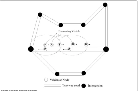
that predictive strategy in Figure 4, the forwarding ve-hicle F sends the packet at time t1 to veve-hicle A because it has greater speed than vehicle B. At time t2, A cannot forward the packet to vehicle C, because it is outside the range of vehicle C. But, If F uses two-hop neighbor in-formation which is achieved by beacon messages, then F will dispatch the packet to vehicle C at time t2 through
neighbor B instead of vehicle A. It is because B is closer to C and C is in turn the closest vehicle to destination D. This minimizes the end-to-end delay further and di-minishes the number of hop counts as well, which makes the routing more efficient. TFOR is based on two-hop neighbor information instead of one hop. Every node maintains two-hop neighbor's table by exchanging Figure 4Routing between junctions.
Car
J1 J2
J4
J3
J5
J6 D
S
Directional flow of vehicles w.r.t Destination D
Non-Directional flow of vehicles w.r.t destination D
Ji Junction i
Source Vehicle
Destination Vehicle
J8
J7
Figure 5Working of TFOR.
one-hop neighbor entries through beaconing. The for-warding node or source node looks its two-hop neighbor table and uses greedy forwarding to dispatch the packet through its neighbor to the neighbor's neighbor that is closest to destination. TFOR uses the carry-and-forward technique of [22] to recover from the local optimum situation.
3.3. An illustrative example
In Figure 5, the source vehicle S sends data packet to destination vehicle D. Source or forwarding vehicle at current junction J1 uses algorithm 1 to compute the next candidate junction based on the traffic flow and the shortest distance to the destination. Roads between the junctions are two lanes. Some lanes are rich in direc-tional and some are rich in non-direcdirec-tional traffic flows with respect to destination. These flows provide enough connectivity for sending packet towards destination. Algorithm 2 and algorithm 3 are used to compute direc-tional and non-direcdirec-tional traffic flows. Source vehicle at current junction J1 computes scores for neighbor junctions. According to algorithm 1, J2 has higher score as compared to J3 because of the shortest distance to the destination and higher traffic density. Therefore, it selects J2 as the next candidate junction instead of J3
because J2 is the closest to destination and has higher traffic directional flow as compared to J3. At J2, source vehicle assigns a score to J4, J5, and J6. It selects J6, as it has a higher score as compared to J4 and J5 because of the shortest distance and higher non-directional flow of traffic. This process continues until packet reaches the destination. Between the junctions, two-hop neighbor information is used as packet-forwarding mechanism that is already described in Section 3.2.2.
4. Simulation results
4.1. Simulation setup
To determine the performance of proposed routing protocol (TFOR), we carried out simulations in GLO-MOSIM. The simulations pertaining to a city scenario, an existing directional protocol (E-GyTAR), and two non-directional routing protocols (GPSR and GSR) for performance comparison were selected. The mobility model [28] for VANETs' simulation should reflect the actual properties and activities of vehicles. There are two categories of mobility models, namely, the macroscopic models and microscopic models. The macroscopic model includes mobility limitations such as speed re-strictions, urban streets, roads, traffic lights, traffic flows, number of lanes, and traffic density. The microscopic model determines vehicle activities with respect to other vehicles as well as the underlying infrastructure. We have chosen VanetMobiSim model [28], which can pro-vide both macro and micro mobility. It is an enhance-ment of the CANU mobility simulation environenhance-ment [2] and is suitable for VANETs.
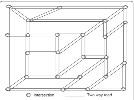
In our simulation, the VanetMobiSim generates ve-hicular mobility patterns, which simulate a 3,000 × 2,900 m2 area. The city simulation area consists of 38 bi-directional roads (with multi-lanes) and 24 intersec-tions, as shown in Figure 6. The vehicular nodes are dis-seminated randomly above the roads and initiate movements in both directions. The intelligent-driver model [23] manages the movements of vehicular nodes on the roads. Table 2 summaries all the essential simula-tion parameters. The simulasimula-tion outcomes revealed below are the average of several simulation runs.
Two way road Intersection
Figure 6The city simulation area.
Table 2 The simulation parameters
Simulation/scenario MAC/routing
Simulation time 200 s MAC protocol 802.11 DCF
Map size 3,000 × 2,900 m2 Channel capacity 2 Mbps
Mobility model VanetMobiSim Transmission range 266 m
Number of intersections 24 Traffic model 16 CBR connections
Number of roads 38 Packet sending rate 0.1 to 1 s
Number of vehicles 75 to 250 Weight factors (α,β) (0.5, 0.5)
4.2. Results
Delivery ratio, end-to-end delay, and routing overhead [19] were selected as evaluation metrics. Based on these metrics, the performance of the selected protocols is be-ing discussed below.
4.2.1 Packet-delivery ratio
Packet-delivery ratio is the ratio of data packets success-fully received at the destination to those produced by the source [24]. Figure 7 reveals the consequences of growing network-traffic density on the packet-delivery ratio with fixed CBR rate. GPSR, GSR, and E-GyTAR exhibit less delivery ratio than TFOR. In GPSR, when greedy forwarding meets the local optimum, then it uses perimeter mode in order to come out of the local optimum situation. In perimeter, the node has a less opportunity to send the packet to a node approaching it in near future. In addition, the perimeter mode uses graph planarization phase that causes partition even in the connected network at the junctions in city environ-ment, which reduces the packet-delivery ratio. GSR does not consider traffic density while selecting junctions stat-ically based on a city street map; some streets may not contain enough vehicles to route the packets towards
the destination, leading to low packet-delivery ratio. In E-GyTAR, the junction selection mechanism is solely based on directional vehicles; in the absence of direc-tional vehicles, it meets local maximum and misses the non-directional vehicles that are available for routing as depicted in Figure 7. This results in reduction of packet-delivery ratio. In TFOR, the dynamic junction selection mechanism uses both directional and non-directional traffic density depending on their availability and short-est path to the dshort-estination. It uses both the paths effi-ciently which contributes to the packet-delivery ratio. As depicted in Figure 7, the two-hop neighbor information is a better choice for deciding the next hop that is clos-est to dclos-estination; it also enhanced the packet-delivery ratio of TFOR. The packet-delivery ratio of all the proto-cols increases as the network density becomes high be-cause connectivity increases.
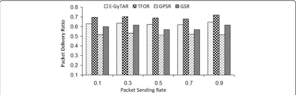
Figure 8 plots the packet-delivery ratio against the packet-sending rate. The packet-delivery ratio decreases if CBR rates are increased to a certain value. It is be-cause this process induces congestion and so the net-work drops certain packets. The perimeter phase in GPSR causes more packet transmission. Hence, high packet sending rate causes decrease in packet-delivery Figure 7Delivery ratio as a function of the number of nodes (at 5 packets/s).
Figure 8Delivery ratio as a function of the packet sending rate (225 nodes).
ratio of GPSR. In GSR, some nodes along the prese-lected paths cause more packet transmission. This causes reduction in packet-delivery ratio because of high packet sending rate. For E-GyTAR and TFOR, the packet-sending rate will not spoil their performance to much in terms of packet-delivery ratio.
4.2.2. End-to-end delay
The end-to-end delay is the average time taken for a packet to pass through the network from its origin to destination [24]. Figure 9 shows that the end-to-end delay of GPSR is more than that of GSR, E-GyTAR, and TFOR. This is because these three approaches employ carry-and-forward approach as an alternative to perim-eter phase of GPSR. Carry-and-forward approach pro-vides more opportunity to locate some appropriate incoming node for forwarding occasionally. The perim-eter phase of GPSR misses this chance. Even in the con-nected network, the perimeter phase with planner graph induces disconnections in the network. It causes delay in relaying the packet from source to destination. When the density of network increases, then there is decrease
in the end-to-end delay of GPSR because the greedy phase becomes more active. The constraints in GSR for deciding the next hop causes larger delay as com-pared to E-GyTAR and TFOR. The end-to-end delay of E-GyTAR is more than TFOR because its junction selection mechanism ignores certain rich-density shortest routes and route the packet along longer paths. In addition, the forwarding between junctions based on two-hop neighbor information shortens the route of packet by choosing the closest neighbor to destination that reduces delay. In two-hop neighbor information, packets traverse less number of hops as compared to one-hop neighbor information. Reduced hop count minimizes the end-to-end delay. In improved greedy forwarding, variable speeds of the vehicles induce packet switching, which is more in one-hop neighbor information as compared to two-hop neighbor information. It also increases the end-to-end delay.
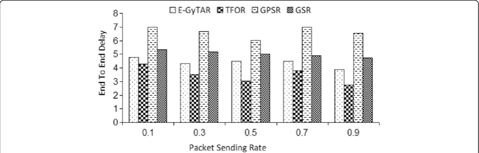
The end-to-end delay of the four protocols at 225 vehicular nodes is plotted against different CBR traffics in Figure 10. The end-to-end delay increases with increase in CBR rates, as more packets amplify congestion in the Figure 9End-to-end delay as a function of the number of nodes (at 5 packets/s).
network. Among these protocols, GPSR has the highest end-to-end delay because of perimeter mode. Due to more control packets transmission, it induces more packets in the network and enhances congestion. The end-to-end delay of GSR is more than that of E-GyTAR and TFOR. The reason is that GSR selects the series of junctions with-out considering the traffic density. Some city streets do not contain enough vehicles to carry packet from source to destination ensuing the retention of packets in the delay buffer for a longer time, ultimately increasing the end-to-end delay. TFOR ensured reduced hop count due to two-hop neighbor information. In addition, our simulation confirms that TFOR decides more efficiently the shortest path to the destination as compared to E-GyTAR. Due to these reasons, it has the least end-to-end delay as com-pared to other routing protocols.
4.2.3. Routing overhead
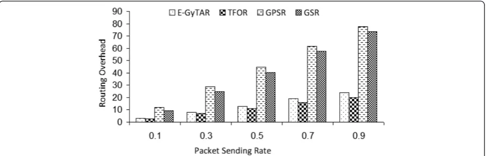
It indicates the ratio of total control packets generated to the total data packets received at the destinations during the complete simulation [24]. Figure 11 plots the routing over-head of all the four protocols against the data-sending rate.
Generally, the routing overhead increases by increas-ing the packet-sendincreas-ing rate. The routincreas-ing overhead is the least for all the four protocols at 0.1 packet-sending rate,
and steadily, it increases with a raise in the packet-sending rate. The routing overhead of GPSR is the highest as compared to other routing protocols because of its heavy beaconing. GSR exhibits greater routing overhead than TFOR and E-GyTAR (note that they-axis of Figure 11 is on a logarithmic scale). This is because GSR sends higher amounts of beacon messages to acquire the locations of its neighbors. Lochert et al. [8] describe that the number of hello messages that GSR generates are thrice than GyTAR. Among all these, routing protocols TFOR has the mini-mum routing overhead because of reduced hop count due to two-hop neighbor information.
Figure 12 exemplifies that the growing vehicular density rises routing overhead for both TFOR and E-GyTAR. The fact is that the amount of beacon messages depends on the number of vehicles. The routing overhead of GPSR is the highest because of perimeter mode which causes more transmission of control messages. GSR is the least efficient for its heavy reliance on the control messages to accomplish the location of neighbors. The rest of the protocols are on par with TFOR marginally outperforming the others.
5. Conclusions
In this paper, we have provided a brief technical analysis of the existing routing studies along with contribution
Figure 12Routing overhead as a function of the number of nodes (at 5 packets/s).
Figure 11Routing overhead as a function of the packet sending rate (225 nodes).
and comments. We have also proposed,‘traffic flow-oriented routing (TFOR) protocol’, a routing protocol for VANETs. It includes two major phases: first, it selects the next junction optimally, based on direc-tional as well as the non-direcdirec-tional density, and secondly, it uses two-hop neighbor information for routing between the junctions. The comparative study of TFOR with other existing approaches concludes that our routing protocol performs significantly better than the other routing approaches in VANETs. Our simu-lation outcomes confirm that the TFOR outperforms E-GyTAR, GPSR, and GSR. TFOR performed best in terms of packet-delivery ratio, with an increase of 7.2% compared to E-GyTAR, more than 16% as compared to GPSR, and 9% as compared to GSR. In case of average end-to-end delay, TFOR performed best, with delays of 15.3% lower than GPSR, 12% lower than GSR, and 7.5% lower than E-GyTAR. The proposed improve for-warding mechanism based on two-hop neighbor con-siderably lowers the average routing overhead as well compared to existing solutions.
In the future, it would be interesting to examine the behavior of TFOR in the presence of one-way roads. A possible research direction could be to design a routing technique that can work in both environments (city and highway).
Competing interests
The authors declare that they have no competing interests.
Author details
1Department of Computer Science, King Khalid University (KKU), Abha, Kingdom of Saudi Arabia.2Department of Computer Science, COMSATS Institute of Information Technology (CIIT), Abbotabad 22060, Pakistan. 3
University Malaysia Sarawak (UNIMAS), Kota Samarahan 94300, Malaysia. 4Department of Compute and Information Sciences, Universidad Carlos III de Madrid (UC3M), Leganés 28914, Spain.
Received: 4 February 2014 Accepted: 30 June 2014 Published: 23 July 2014
References
1. H Hartenstein, KP Laberteaux,VANET Vehicular Applications and Inter-Networking Technologies, 1st edn. (Wiley Online Library, United Kingdom, UK, 2010) 2. S Jaap, M Bechler, L Wolf, Evaluation of routing protocols for vehicular ad
hoc networks in city traffic scenarios, inProceedings of the 5th International Conference on Intelligent Transportation Systems Telecommunications (ITST) (Brest, France, 2005)
3. KC Lee, U Lee, M Gerla,Advances in Vehicular Ad-Hoc Networks: Developments and Challenges, chapter Survey of Routing Protocols in Vehicular Ad Hoc Networks (IGI Global, Hershey, 2009)
4. YW Lin, YS Chen, SL Lee, Routing protocols in vehicular ad hoc networks: a survey and future perspectives. J. Inf. Sci. Eng.26(3), 913–932 (2010) 5. B Nazir, H Hasbullah,Energy balanced clustering in wireless sensor network,
International Symposium in Information Technology (ITSim), 2010, pp. 569–574
6. B Nazir, H Hasbullah, Energy efficient and QoS aware routing protocol for Clustered Wireless Sensor Network. Comput. Electr. Eng.
39(8), 2425–2441 (2013)
7. B Nazir, H Hasbullah, SA Madani, Sleep/wake scheduling scheme for minimizing end-to-end delay in multi-hop wireless sensor networks. EURASIP J. Wirel. Commun. Netw.92(1), 1–14 (2011)
8. C Lochert, H Hartenstein, J Tian, H Fu¨ßler, D Hermann, M Mauve, A routing strategy for vehicular ad hoc networks in city environments, inProceedings of the Intelligent Vehicles Symposium, 2003. IEEE, 2003, pp. 156–161 9. A Dahiya, RK Chauhan, A comparative study of MANET and VANET
environment. J. Comput2(7), 87–91 (2010)
10. J Gong, CZ Xu, J Holle, Predictive directional greedy routing in vehicular ad hoc networks, inDistributed Computing Systems Workshops, 2007. ICDCSW '07. 27th International Conference on June 2007
11. B Karp, HT Kung, GPSR: greedy perimeter stateless routing for wireless networks, inProceedings of the 6th annual international conference on Mobile computing and networking, MobiCom '00(ACM, New York, NY, USA, 2000), pp. 243–254
12. F Li, Y Wang, Routing in vehicular ad hoc networks: a survey. Vehicular Technology Maga- zine, IEEE2(2), 12–22 (2007)
13. A Rahim, I Ahmad, ZS Khan, M Sher, A Javed, M Shoaib, R Mahmood, A comparative study of mobile and vehicular adhoc networks. Int. J. Recent Trends Eng.2(4), 195–197 (2009)
14. GMT Abdalla, MA Abu-Rgheff, SM Senouci, Current trends in vehicular ad hoc networks. UbiCC Journal, Special Issue on UbiRoads (2008)
15. DB Johnson, DA Maltz, Dynamic source routing in ad hoc wireless networks, inMobile Computing(Kluwer Academic Publishers, Alphen aan den Rijn, 1996), pp. 153–181
16. CE Perkins, EM Royer, Ad-hoc on-demand distance vector routing, inMobile Computing Systems and Applications, 1999. Proceedings. WMCSA '99. Second IEEE Workshop, 1999, pp. 90–100
17. T Clausen, P Jacquet,Optimized Link State Routing Protocol (OLSR), RFC 3626 (Internet Engineering Task Force, 2003)
18. AK Gupta, H Sadawarti, AK Verma, Review of various routing protocols for MANETs. Int. J. Inf. Electron. Eng.1(3), 1–9 (2011)
19. W Kieß, H Fu¨ßler, J Widmer, M Mauve, Hierarchical location service for mobile ad-hoc networks: SIGMOBILE Mobile. Comput. Commun. Rev. 1(2), 47–58 (2004)
20. J Li, J Jannotti, DSJ Decouto, DR Karger, R Morris, A scalable location service for geographic ad hoc routing, inProceedings of the 6th annual international
conference on Mobile computing and networking, MobiCom '00(ACM, New
York, NY, USA, 2000), pp. 120–130
21. M Kasemann, H Fu¨ßler, H Hartenstein, M Mauve,A reactive location service for mobile ad hoc networks, Technical Report, TR-14-2002(Dept. of Computer Science, Univ. of Mannheim, 2002)
22. C Lochert, M Mauve, H Fu¨ßler, H Hartenstein, Geographic routing in city scenarios. SIGMOBILE Mob. Comput. Commun. Rev.9, 69–72 (2005) 23. D Tian, K Shafiee, VCM Leung, Position-based directional vehicular routing,
inProceeding of the Global Telecommunications Conference, GLOBECOM (IEEE, Hoboken, 2009), pp. 1–6
24. M Jerbi, S-M Senouci, R Meraihi, Y Ghamri-Doudane, An improved vehicular ad hoc routing protocol for city environments, inCommunications, 2007. ICC '07. IEEE International Conference, 2007, pp. 3972–3979
25. BC Seet, G Liu, BS Lee, CH Foh, KJ Wong, KK Lee, A-STAR, A mobile ad hoc routing strategy for metropolis vehicular communications, inLecture Notes in Computer Science: NETWORKING 2004, Networking Technologies, Services, and Protocols; Performance of Computer and Communication Networks; Mobile and Wireless Communications, 2004, pp. 989–999
26. S Bilal, SA Madani, IA Khan, Enhanced junction selection mechanism for routing protocol in VANETs. Arab J. Inf. Technol.8(4), 422–429 (2011) 27. K Prasanth, K Duraiswamy, K Jayasudha, C Chandrasekar, K Prasanth, K
Duraiswamy, K Jayasudha, C Chandrasekar, Improved packet forwarding approach in vehicular Ad Hoc networks using RDGR algorithm. International Journal of Next- Generation Networks (IJNGN)2(1), 64–77 (2010)
28. J Harri, F Filali, C Bonnet, M Fiore, VanetMobiSim: generating realistic mobility patterns for VANETs, inProceedings of the 3rd international workshop on Vehicular ad hoc networks, VANET'06(ACM, New York, NY, USA, 2006), pp. 96–97
doi:10.1186/1687-1499-2014-121