Volume 2008, Article ID 372078,8pages doi:10.1155/2008/372078
Research Article
Transmitter Layering for Multiuser MIMO Systems
Christian Schlegel, Dmitri Truhachev, and Zachary Bagley
Department of Electrical and Computer Engineering, University of Alberta, Edmonton, Alberta, Canada T6G 2V4
Correspondence should be addressed to Christian Schlegel,[email protected]
Received 1 September 2007; Accepted 15 February 2008
Recommended by Nihar Jindal
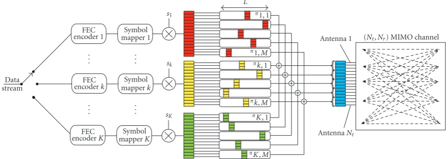
A novel structure for multiple antenna transmissions utilizing space-time dispersion is proposed, where the original data stream is divided intoKsubstreams which are modulated onto all available transmit antennas using stream-specific transmit signature sequences. In order to achieve this, the transmit antennas are partitioned intoMgroups of antennas, called partitions. The signals from theKdata streams are independently interleaved by partition over the entire transmission frame. The interleaved partitions are then added over allKsubstreams prior to transmission over the MIMO channel. At the receiver, a low-complexity iterative de-tector adapted from recent CDMA multiuser detection research is used. It is shown that with careful substream power assignments this transmission methodology can efficiently utilize the capacity of rank-deficient channels as it can approach the capacity limits of the multiple antenna channel closely over the entire range of available signal-to-noise ratios and system sizes. This transmission methodology and receiver structure are then applied to multiuser MIMO systems where several multiple antenna terminals com-municate concurrently to a joint receiver. It is shown that different received power levels from the different MIMO terminals can be beneficial and that higher spectral efficiencies can be achieved than in the single-terminal case.
Copyright © 2008 Christian Schlegel et al. This is an open access article distributed under the Creative Commons Attribution License, which permits unrestricted use, distribution, and reproduction in any medium, provided the original work is properly cited.
1. INTRODUCTION
Emerging wireless networks are likely to incorporate multiple-input multiple-output (MIMO) antenna systems in order to meet requirements for high transmission capacities and link availability. Since their introduction by Foschini [1], and the prototyping of Bell Lab’s BLAST project [2], research into MIMO transmission has exploded, and a large body of work has been published in recent years. While the theory of MIMO transmission [3] and the potential capacity benefits are well understood, efficient transmission systems are still under intensive research. Foschini’s cancellation and nulling receiver works well in theory and approaches the capacity of an uncorrelated MIMO channel, but its performance de-grades rapidly in reduced-rank channels, as typically hap-pens in outdoor wireless transmission.
Various low-complexity receivers based on linear ma-trix methods such as the zero-forcing (ZF) and the min-imum mean-square error (MMSE) receivers have also re-ceived much attention. If the MIMO channel rank is limited by the number of transmit antennas,Nt, and if there are more
than about twice as many uncorrelated receive antennas,Nr,
it can be shown that linear methods perform very well, and
indeed come close to the capacity of the channel as long as
Nt Nr/2 [4]. However, this typically requires significantly
more receive antennas than transmit antennas and may thus not be practical for downlink transmissions to mobile termi-nals, or where multiple MIMO terminals communicate con-currently to a central receiver. In such rank-deficient situa-tions, linear systems quickly fall apart and fail to provide high channel efficiencies.
Data stream
FEC encoder 1
FEC encoderk
FEC encoderK
Symbol mapper 1
Symbol mapperk
Symbol mapperK .
. .
. . .
. . .
. . .
s1
sk
sK
L
π1, 1
π1,M
πk, 1
πk,M πK, 1
πK,M
Antenna 1
AntennaNt
(Nt,Nr) MIMO channel
Figure1: Strucutre of the proposed partitioned MIMO transmitter.
The paper is organized as follows.Section 2presents the formal system description and the iterative low-complexity demodulation process. In Section 3, an asymptotic density evolution analysis is presented leading to an accurate itera-tion equaitera-tion describing the signal-to-interference progres-sion of the different data streams in the demodulator. It is shown how higher-order modulations can be accommo-dated to increase spectral efficiency as signal-to-noise ratio becomes available. This methodology can approach the ca-pacity of the channel closely using unequal power distribu-tions over different data streams utilizing generalized PAM constellations. A density-evolution-based analysis is used to evaluate achievable spectral efficiencies and numerical simu-lation examples are given in supporting evidence.Section 4 discusses extensions to multiuser MIMO networks of trans-mitters, andSection 5concludes the paper.
2. SYSTEM MODEL
2.1. Transmitter
We consider a transmission system using a multiple-input multiple-output (MIMO) system with Nt transmit andNr
receive antennas. The input data stream is divided into K
data streams which are subsequently independently encoded using block FEC codes of lengthL. Each of the output bi-nary symbols is mapped into an antipodal signal{±1}. The block of modulated binary antipodal symbols for streamkis denoted by (vk,0,vk,1,. . .,vk,L−1).
Each symbolvk,l is multiplied by a binary antenna
sig-nature sequence sk = (sk,0,sk,1,. . .,sk,Nt−1)T whose entries are selected from the set{±1/Nt}for energy normalization.
These uniqueantenna signatureshave the effect of dispersing the data streams over allNtantennas and creating a balanced
load on all transmit RF chains (the reader will appreciate that this dispersion can of course be created over multiple trans-mission intervals, increasing the effectiveNt). This
transmit-ter arrangement is illustrated inFigure 1.
The K Nt-dimensional signal vectors vk,lsk are
divid-ed intoM equal-length partitions,vk,lsk,m = vk,l(sk,m(Nt/M),
sk,m(Nt/M)+1,. . .,sk,(m+1)(Nt/M)−1)
T,m=0,. . .,M−1, and each
of these partitions is fed into an independent interleaverπk,m, m=0,. . .,M−1 of size equal to the code frame lengthL(see Figure 1). This creates an implicit repetition code of rate 1/M
for each stream, which, combined with the MIMO channel, forms a concatenated structure suggestive of iterative pro-cessing, seeSection 2.2.
Different partitions of the same symbolvk,lare
transmit-ted at different time intervals and over different antennas, and therefore both temporal and spatial diversities are gener-ated. By doing this, we ensure a dispersion of the transmitted information and reduce correlation between received parti-tions belonging to the same symbolvk,l. Denoting the
inter-leaved symbol of streamk, partitionm, and transmitted at timelbyvk,m,l, the discrete signal transmitted from antenna nat timelis given by
xn,l= K
k=1
Pkvk,m,lsk,n; m=
n Nt/M
, (1)
where Pk is the total power (energy/symbol) of transmit
streamk, distributed over theNttransmit antennas.
Note that this basic system model describes a number of key scenarios: (i) for higher-order modulationswe groupB
data streams together which will form a 2B-ary PAM
sym-bol. This is done as follows: the antenna sequence partitions sk,mfor the data streams forming the combined PAM
sym-bol stream are chosen orthogonal, and the powers are set such thatPk,b ∝ 4b;b = 0,. . .,B−1. It is easy to see that
such a power distribution on binary antipodal signals gener-ates the familiar equispaced PAM symbols. Furthermore, or-thogonality of the antenna signature partitions requires that
Nt/M ≥B, but is otherwise easy to satisfy. It is
terminals transmit to a central receiver (MIMO multiuser). This implies that the K data streams are grouped into U
groups, where U is the number of distinct MIMO termi-nals. The only difference between the basic receiver system discussed below, and a MIMO multiuser receiver is that the signal asynchronicity between the different terminals needs to be accounted for at the receiver.
In all cases, the signals in (1) are transmitted from the
Ntantennas over a channel with gain matrix at time instant l given byHl, where the channel matrix entries, hr,n,l, are
the path gains between transmit antennanand receive an-tennar at timel. As is customary, we assume for now that these gains are randomly and independently distributed with power E|hr,n,l|2 = 1. It is also assumed that the channel
changes slowly with respect to the symbol rate and is known at the receiver. The signal received by theNrantennas is then
yl=Hlxl+ηl=
Detection and decoding are performed by adapting an ef-ficient two-stage scheme initially proposed for multiuser CDMA demodulation [5–7]. The first stage is an iterative de-modulator by means of simple interference cancellation us-ing soft-bit estimation and matched filterus-ing. It aims at de-livering soft symbol estimates to the external forward error correction (FEC) decoders for each data stream. The success of the FEC decoders depends on the level of residual noise and interference in each demodulated stream. When the fi-nal sigfi-nal-to-noise ratio produced by the iterative demodu-lation stage is above the code threshold, the receiver can de-liver error-free data. We will quantify the conditions for this to happen below.
Figure 2depicts the iterative demodulation process. The received signal at each antennaris given by
yr=
all channel components in yr which contain the interleaved
symbolvk,m. These matched filter outputs are given by
zk,m,r=yr
(m+1)(Nt/M)−1
n=m(Nt/M)
sk,nh∗r,n (4)
basically matched-filter combining allNt/Mcomponents of
signal partitionvk,mthat arrive at antennar. Substituting the
signalsyrwe calculate after some manipulations
zk,m,r=
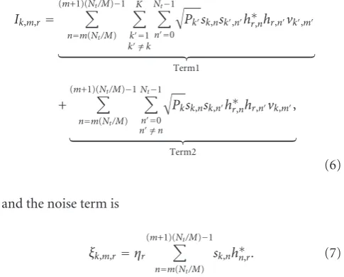
The interference termIk,m,rconsists of two contributions: (i)
interference from other data streams, and (ii) interference from thekth data stream itself. These two contributions are given by
and the noise term is
ξk,m,r=ηr
(m+1)(Nt/M)−1
n=m(Nt/M)
sk,nh∗n,r. (7)
We will need the variances of these different terms in the later development, given by
After deinterleaving the signal partitions zk,m,r in (5) into zk,m,r, the receiver then aggregates signal partitions by
sum-ming the signals over all antennasr to obtain the aggregate matched filtered signal for partitionmand streamk:
R
To external FEC decoders
yk(i,)m,0
Figure2: Signal flow chart of the partitioned receiver highlighted for streamkand antennar.
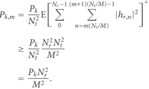
Because of the assumption of unit-variance channel gains
E|hr,n|2=1,the signal power (11) of a single partition is
After deinterleaving (5) and aggregating (11) we obtain
M partitionszk,m,l for each symbolvk,l. Using these we
cal-culate M soft symbol estimates vk,m which are used to
re-modulate the transmitted signal for interference cancella-tion in the received signal. In a subsequent iteracancella-tion, the cancelled signal is then matched filtered again and new soft symbol estimates are derived according to the signal flow of Figure 2.
The remodulated signals for each partitionmfor receive antennarat iterationiare
y(ki,)m,r=Pk
(m+1)(Nt/M)−1
n=m(Nt/M)
hr,nvk(,mi)sk,n, (13)
which are subsequently used to generate the canceled signal
yr−
for data stream k, which in turn is processed again by the matched filters to producez(ki,+1)m as in (11). This process is
repeated for a number of iterations, after which final soft symbol estimates of the binary symbolsvk,lare formed and
passed on toKstandard FEC decoders.
2.3. Soft symbol calculation and error variance
The observationszk(i,+1)m depend explicitly on the soft-symbol
estimates vk(i,)m through the filtering and cancelation steps.
These soft estimates in turn are computed from the matched filtered partitionsz(ki,)mof the previous iteration round under
observance of the extrinsic information exchange principle [4] as
which is the optimal local minimum-variance estimate of
vk,mgiven thatIk,mandζk,mare combined from a Gaussian random variable with varianceσ2
i. This is easily shown to be
true under some mild conditions.
The variance of the symbol estimates (15) will be re-quired in the SNR evolution analysis inSection 3. Defining this variance at iteration round iasσ2
v,i,k = E|vk−vk(i,)m|2,
and assuming that correlation between partitions is negli-gible due to sufficiently large interleaving (see Figure 1), it can be calculated adapting the development in [8] for CDMA as is passed to the error control decoder for streamk. The fi-nal sigfi-nal-to-noise/interference ratio ofz(kI)is what primarily
3. DENSITY EVOLUTION ANALYSIS
3.1. Variance evolution
The interference and noise on streamkare given by (8)–(10) giving an effective per symbol noise/interference variance at the partition level in (11) at iterationiof
σi2≤
which is common to all streams. The upper bound in (17) contains the self term forkandm, which, however, becomes negligible asKandMgrow—see (8) and (9). Using (16) in (17), we obtain
izes the noise power per symbol and antenna, we further ob-tain
The dynamic system equation (19) is analogous to that oc-curring in the CDMA case discussed in [8]. We further as-sume, without loss of generality, that the powers are ordered asP1 ≤P2 ≤ · · · ≤PK. DenotingPk =P(k), and lettingK
andMbecome large, we use the continuous approximation
distribution over all data streams and a nondecreasing func-tion, and we have introduced the parameterα=K/Nr, called
thesystem aspect ratio.
If the signal-to-noise ratioT(0)/σ2
∞of the lowest-power
data streamk=1 at the output of the demodulator is higher than the target performance thresholdμFECof the FEC code
used, all streams can be decoded to target performance. This allows us to derive the following convergence condition from (20):
In [9] it is shown that the continuous power distribution
T(u)=eau, u∈[0,α], (22)
allows the convergence condition (21) to hold for arbitrary aspect ratiosK/Nr, as long as the constanta≥a0=2 ln 2. As
shown in [9], this constant does not depend on the system aspect ratio. Thus, for two different ratios α < α the cor-responding power distributionsT(u) andT(u) coincide for
u≤α, that is,
T(u)=T(u)=eau, u∈[0,α]. (23)
The importance of this results is that new data streams can al-ways be added at the cost of increased average power, without affecting decodability of the existing streams. Furthermore, in [9] it is shown that the distribution (22) allows such a sys-tem to approach the capacity of the Gaussian MAC channel to within less than 1 bit of capacity.
3.2. PAM modulation
Note that using the PAM modulation method proposed in Section 2.1applied to a single MIIMO link does not follow thecontinuouspower distribution of (23), but is compatible with that distribution.
In the case of PAM modulations, the variance transfer function (19) is
whereKbis the number of data streams at modulation levelb,
andP0is the total received power of the lowest modulation
levelb = 0. Defining the signal-to-noise/interference ratio for the lowest modulation level asμ=P0/σi2andαb=Kb/Nr
as the level-baspect ratio, we obtain the convergence equa-tion
which must hold for
μ≥μFEC, (26)
which is the signal-to-noise ratio threshold of the FEC code used.Figure 3shows the right-hand side of (25) minus 1 for a signal-to-noise ratioP0/σ2 =20 dB. As long as this diff
er-ence does not exceed the zero threshold forμ <20 dB, con-vergence to full interference cancelation is possible and we say the ratioαis supportable. The maximal achievable spec-tral efficiencies are 2.08, 2.52, and 3.21 bits/dimension, for 2-PAM, 4-PAM, and 8-PAM modulations, respectively.
−1
−0.8
−0.6
−0.4
−0.2 0 0.2
−10 −5 0 5 10 15 20
μ(dB)
Binary:b=0 Limit load:α0=2.08
4-PAM:b=1 Limit load:α1=1.26
8-PAM:b=2 Limit load:α2=1.07
Figure 3: Convergence function (25) for binary, 4-PAM, and 8-PAM modulations and large signal-to-noise ratios.
1 2 3 4 5 6
Su
m
capacit
y
(bits/dimension)
0 2 4 6 8 10 12 14 16 18 20
AverageEb/N0(dB)
1 2 3 4 5 Per dimension
maximal capacity
(1) (1) (2)
(2) (3) (3) (4)
(4)
(1) 2-PAM modulation (2) 4-PAM modulation (3) 8-PAM modulation (4) 16-PAM modulation
Figure4: Achievable spectral efficiencies using iterative demodula-tion of various PAM constellademodula-tions.
more than twice the number of orthogonal dimensions. For higher PAM constellations,αb →1 rapidly from above, and
we achieve a capacity equal to that of orthogonal signaling. Note: even though the actual signals used will be two-dimensional complex equivalent, we have carried out our analysis normalized per dimension. This is permissible, since the phase offsets between different components of the same signal are phase-corrected by the matched filters, and signals from all interfering partitions affect the receiver analysis only via their interference variance, and therefore random phase offsets are not relevant.
3.3. Numerical examples
In order to support our theoretical findings, the following situations have been simulated. A system withNt Nrwas
simulated on a Rayleigh fading MIMO channel. This is a situ-ation which is pretty hopeless for a linear receiver. The block lengths used for the simulations wereL =2000 with 30–60 iterations, andNt =M=100, that is, the number of
trans-mit antennas equals the number of partitions. The modula-tion parameters are as follows: for PAM-16,K=28,Nr=8, αb=0.875, for PAM-8,K=27,Nr =10αb=0.9, for
PAM-8,K =26,Nr =12 withαb =1.08, and for PAM-2,K =9, Nr=5 withαb=1.8 andNt=M=20. The gaps to the
the-oretical capacity values of about 25% are due to two effects. (i) A finite number of iterations requires lowering the max-imal loads, and (ii) the relatively small values of the simu-lation parameters required imposes Diophantine constraints causing a certain granularity in the partial loadsαb. An
ex-tension of these concepts to include modulation over many time intervals, for example, by combining transmitter layer-ing with signal spreadlayer-ing will ease these constraints. Also, no attempt was made to use orthogonal sequences for the power levels of a given stream.
4. MULTI-USER MIMO SYSTEMS
Multiuser MIMO systems are, as illustrated inFigure 5, com-munications arrangements where spatially disjoint MIMO transmitters communicate with a central receiver which pro-cesses the different MIMO signal streams concurrently. Fo-cussing consideration on an uplink application, we can view such an arrangement as a single large MIMO system. The capacity of this composite MIMO system forms an upper bound of what is achievable by the distributed transmitters. The receiver proposed in this paper is fully applicable to this case, since it layers each data stream separately, irrespective of data stream colocation. The only additional complexity that needs to be considered stems from the fact that the diff er-ent MIMO transmissions are asynchronous with respect to each other. However, since the iterative receiver uses only ba-sic cancellation operations, this asynchronicity can, in prin-ciple, be incorporated easily into the remodulation process in (31). For simplicity, we make the unrealistic assumption that the terminals are synchronous, noting that the actual inter-ference levels for an asynchronous system are actually lower bounded by the synchronous case.
We considerUdistinct terminals, each equipped with the proposed space-time dispersion transmitter. All the termi-nals access a common receiver performing a two-stage lay-ering demodulation. For simplicity, we assume that all ter-minals have the same parameters, that is, number of data streamsK, block lengthL, and number of antennasNt. The
antenna signaturessu,kare uniquely chosen for each of the U×K transmitted data streams. The received signal in the multiuser case is—analogously to (3)—given by
yr= U
u=1
Nt−1
n=0
hu,r,nxu,n+ηr
=
Nt−1
n=0
U
u=1
hu,r,n K
k=1
Pu,kvu,k,msu,k,n+ηr
(27)
forr∈0, 1,. . .,Nr−1. The matched filtering receiver
opera-tion produces the samples
zu,k,m,r=yr
(m+1)(Nt/M)−1
n=m(Nt/M)
MIMO user 1
MIMO useru
MIMO userU
Joint iterative demodulator
. . . . . .
z(1,1I)
z(kI,)u
z(KI),U
Figure5: Structure of the proposed partitioned multiterminal MIMO transmission and reception.
During the detection stage, the iterative algorithm calculates soft-bit estimates for each terminal, data stream, and parti-tion, as
vu(i,)k,m=tanh ⎛ ⎜ ⎜ ⎜ ⎝
Pu,kNr M
M−1
m
(m=/m)
z(ui,)k,m
σ2
i ⎞ ⎟ ⎟ ⎟
⎠, (29)
and canceled signal streams are generated as
yr− U
u=1
K
k=1
M−1
m=0
(mk,u)=/(m,k,u)
yk(i),m,u,r, (30)
where the remodulated signals for each partitionmfor re-ceive antennarat iterationiare found as
y(ki,)m,u,r=
Pu,k
(m+1)(Nt/M)−1
n=m(Nt/M)
hu,r,nvu(,ik),msu,k,n. (31)
New valuesz(ui,+1)k,m,rare obtained by repeated matched filtering of the cancelled signal.
In the multiterminal case, the joint distribution of the powers{Pu,k}is playing the role of{Pk}in the single
termi-nal case. Thus, the effective noise/interference variance per symbol of the signal partition at iterationiis given by
σ2
i ≤
Nr M
U
u=1
K
k=1
Pu,kσv2,i−1,u,k+ Nr Mσ
2. (32)
Furthermore, using arguments analogous to (18)–(23) it can be shown that if the continuous approximation of the joint stream power distributionPu,ksatisfies (23), again, any
sys-tem aspect ratioα=KU/Nrcan be achieved and the system
operating point can approach the multiple access channel ca-pacity. It can also be concluded that introduction of new ter-minals does not degrade system performance as long as the powers of the new data streams fit into the supportable (ge-ometric) power profile.
From a practical point of view, unequal received pow-ers from different terminals may actually be beneficial as il-lustrated inFigure 6, where three MIMO terminals access a common receiver with received power distributions such that the second user’s power is 6 dB less than that of the first, and the third user’s power is 9 dB below the strongest user. The x-axis is labeled by the average Eb/N0, as in Figure 4.
The dashed lines are the single-MIMO-channel achievable spectral efficiencies. The solid lines are those achievable with the specific 3-MIMO-terminal system whose parameters are discussed below. As expected, the lower-order constellation benefits the most from different power distributions since the user power variation has its strongest impact. In fact, the ad-vantage of higher-order PAM modulation starts to disappear, and, in situations with many different terminals at different received powers, 2-PAM will be sufficient to attain most of the channel’s capacity.
Received power distributions other than the one simu-lated cause similarly augmented spectral efficiencies, but, of course, decodability of the lower energy terminals needs to be assured since the substream signal-to-noise ratio diff er-ences are preserved through the iterative demodulation pro-cess. The reader can also easily see how various rate-adaptive transmission schemes can easily be accommodated by this it-erative demodulation receiver.
1 2 3 4 5 6
Su
m
capacit
y
(bits/dimension)
0 2 4 6 8 10 12 14 16 18 20
AverageEb/N0(dB)
1 2 3 4 5 Per dimension
maximal capacity
(1)
(3) (3)
(2) (4)
(4)
(1) 2-PAM modulation (2) 4-PAM modulation (3) 8-PAM modulation (4) 16-PAM modulation
Figure6: Achievable spectral efficiencies for three MIMO termi-nals with relative power differences of 0 dB,−6 dB, and−9 dB via simulations, plotted against theaveragebit energy-to-noise-power ratio.
use independent Rayleigh fading for each path. The system parameters areNt=M=100 for all cases; for PAM-16,K=
16,Nr =13; for PAM-8,K =6,Nr =6; for PAM-4,K =8
withNr=9, and for PAM-2,K=5 withNr =6. We can see
that the achievable spectral efficiencies exceed those of the single terminal case and are close to the analytical limiting values.
5. CONCLUSIONS
We have presented and analyzed a two-stage iterative demod-ulation and decoding receiver of low complexity which can achieve the multiple-access capacity of the single, or mul-tiuser MIMO channel given an exponential received power distribution of the different data streams. However, practi-cal systems with simple PAM modulation formats whose de-composed binary powers follow this distribution approach the channel capacity over a wide range of operating SNRs in both the single-user MIMO as well as the multiuser MIMO situations, and can exceed the capacity of PAM constella-tions on orthogonal carriers—this can be viewed as akin to a constellation shaping gain. The transmitter operates by layer-ing each transmitted signal over all available transmit anten-nas with groups of transmit signals (partitions) fed through different interleavers before transmission to achieve spatial and temporal spreading. The receiver relies on a conceptually simple iterative demodulator which repeatedly recombines and filters partitioned received signals followed by “off -the-shelf ” standard error control decoders.
ACKNOWLEDGMENTS
This work was supported in part by iCore Alberta and the Alberta Ingenuity Fund.
REFERENCES
[1] G. J. Foschini, “Layered space-time architecture for wireless communication in a fading environment when using multi-element antennas,”Bell Labs Technical Journal, vol. 1, no. 2, pp. 41–59, 1996.
[2] P. W. Wolniansky, G. J. Foschini, G. D. Golden, and R. A. Valen-zuela, “V-BLAST: an architecture for realizing very high data rates over the rich-scattering wireless channel,” inProceedings of the URSI International Symposium on Signals, Systems, and Elec-tronics (ISSSE ’98), pp. 295–300, Pisa, Italy, September 1998. [3] E. Telatar, “Capacity of multi-antenna Gaussian channels,”
Eu-ropean Transactions on Telecommunications, vol. 42, no. 2–4, pp. 1617–1627, 1999.
[4] C. Schlegel and A. Grant,Coordinated Multiple User Communi-cations, Springer, New York, NY, USA, 2006.
[5] C. Schlegel, “CDMA with partitioned spreading,”IEEE Com-munications Letters, vol. 11, no. 12, pp. 913–915, 2007. [6] C. Schlegel, D. Truhachev, and L. Krzymien, “Iterative
mul-tiuser detection of random CDMA using partitioned spread-ing,” inProceedings of the 4th International Symposium on Turbo Codes and Related Topics, Munich, Germany, April 2006. [7] L. Krzymien, D. Truhachev, and C. Schlegel, “Coded random
CDMA with partitioned spreading,” inProceedings of the 44th Annual Allerton Conference on Communication, Control, and Computing, Monticello, Ill, USA, September 2006.
[8] C. Schlegel, Z. Shi, and M. Burnashev, “Optimal power/rate allocation and code selection for iterative joint detection of coded random CDMA,”IEEE Transactions on Information The-ory, vol. 52, no. 9, pp. 4286–4294, 2006.