R E S E A R C H
Open Access
Buffer-aided relaying improves both
throughput and end-to-end delay
Javad Hajipour
1*, Rukhsana Ruby
1, Amr Mohamed
2and Victor C. M. Leung
1Abstract
Buffer-aided relaying has recently attracted a lot of attention due to the improvement in the system throughput. However, a side effect usually deemed is that buffering at relay nodes results in the increase of packet delays. In this paper, we study the effect of buffering at relays on the end-to-end delay of users’ data, from the time they arrive at the source until delivery to the destination. We use simple discussions to provide an insight on the overall waiting time of the packets in the system, taking into account the queue dynamics both in the source and relay. We analyze the end-to-end delay in the relay networks with Bernoulli data arrivals and channel conditions and prove that the data packets experience lower average end-to-end delay in the buffer-aided relaying system compared with the conventional one. Moreover, using intuitive generalizations, we conclude that the use of buffers at relays improves not only throughput but ironically the average end-to-end packet delay. Through extensive simulations, we validate our analytical results for the system when the data arrival and channel condition processes follow Bernoulli distribution. Furthermore, via the simulations under the settings of practical systems, we confirm our intuition for the general scenarios.
Keywords: Wireless relay networks, Buffering capability, Throughput, Delay
1 Introduction
Wireless relays have received significant attention in the past decade because of their capability to enhance the capacity and coverage of wireless networks. The authors in [1] have investigated the bounds on the ergodic and outage capacities for wireless relay channels in Rayleigh fading environment. Similarly, Azarian et al. [2] have stud-ied amplify-and-forward (AF) and decode-and-forward (DF) relay channels and proposed variants of these protocols for reaching the bounds on achievable diversity-multiplexing trade-offs. Employing wireless relays in con-temporary cellular networks is also considered as a promising solution for meeting the growing demands of users in these systems, due to the cost-effective and fast deployment possibility of relay stations [3]. There-fore, there has been extensive research in this area to identify the challenges and address them accordingly [4–7]. In particular, Ng et al. [4] studied resource alloca-tion in an orthogonal frequency division multiple access (OFDMA)-based system with AF relays and proposed
*Correspondence: [email protected]
1ECE Department, The University of British Columbia, Vancouver, Canada Full list of author information is available at the end of the article
optimal subchannel and power allocation for maximiz-ing the system goodput. In [5], the authors investigated joint relay selection and resource allocation taking link asymmetry and imperfect channel state information (CSI) into account. Zhang et al. [6, 7] studied resource alloca-tion to provide quality of service (QoS) for the users with minimum rate or maximum packet delay requirements.
Usually in the literature in this area, it is assumed that relaying procedure is performed in two consecutive sub-slots of a transmission interval; i.e., in the first subslot, the base station (BS) transmits to the relay and in the second one, the relay forwards the received data to the mobile terminal. We refer to this method as “conventional relay-ing” in which the end-to-end transmission rate in each transmission interval is limited by the poorest link qual-ity. Recently, it has been shown that using buffer in the relay node can improve the system throughput [8–11]. This is achieved due to the fact that the buffering capa-bility allows the relay to store packets when its channel condition is bad and transmit when it is good. Motivated by this, several other works have studied buffer-aided relaying scheme in different areas [12–16]. While Krikidis et al. [12] have studied adaptive relay link selection in a single-source multi-relay system, the authors of [13] have
investigated that for a multi-source multi-relay scenario. On the other hand, Ahmed et al. [14] have discussed the advantages of buffer-aided relaying for the operation of nodes with energy harvesting capability. Moreover, Liu et al. and Darabi et al. [15, 16] have confirmed the advan-tage of using buffer-aided relays in two-way relaying and cognitive radio networks, respectively.
Any improvement in a system usually comes at a cost. In the case of buffer-aided relaying, the cost is usu-ally deemed to be the increase in packet delays due to queueing in the relay. Consequently, the works in [8–11] have tried to investigate and discuss the trade-off between throughput and delay. This is however based on the assumption of infinitely backlogged buffers in the source (i.e., BS) and considering the queueing delay only at the relay buffer without taking into account the queue dynamics at the BS.
In this paper, we aim at filling the abovementioned gap by taking into account the queue dynamics both in the source node and the relay node. Whereas the exist-ing literature [8–11] mostly considers packet delay as the time delay between packet transmission (departure) at the source node and reception (arrival) at the destination node, in this paper, we study end-to-end packet delay, i.e., the delay that data packets experience since their arrival at the source node until reception at the destination node. The difference between the end-to-end delay considered in this paper and the delay investigated in the aforemen-tioned works is that the end-to-end delay includes both the queueing delay that data packets experience in the source node and the time interval between their transmis-sion at the source and reception at the destination. Noting that the delay perceived by the end user is affected by the queueing at both the BS and the relay, in this paper, we investigate the effect of buffer-aided relaying on the end-to-end packet delay. For this, we first provide sim-ple reasoning and discuss the cause of queue formation in a simple queueing system. Based on that, we provide an insight on the delay performance in the buffer-aided and conventional relaying systems. Then, we study the delay performance when data arrival and channel condition processes of the system follow Bernoulli distribution and derive closed form expressions for the average end-to-end packet delay. Using these, we prove that the buffer-aided relaying system incurs lower average end-to-end packet
delay compared with the conventional one. Finally, we dis-cuss general scenarios and based on intuitive disdis-cussions, we conclude that buffering at relays improves the sys-tem throughput as well as the average end-to-end packet delay. Using extensive simulations, we verify our analysis and demonstrate the validity of the presented perspec-tive. To the best of our knowledge, this is the first work that discusses the effect of buffering at relays on the over-all waiting time in a relay-based network and provides the above conclusion and insight. We note that the dis-cussions in this paper assume infinite buffer capacities in the BS and relay. However, the insights provided can be used in future works to study the scenarios with limited buffer capacities, where the buffer overflow events can also affect the end-to-end packet delays due to the need for repeated transmissions. In such scenarios, for reducing buffer overflow incidents, a buffer-aware source rate con-trol mechanism can be exploited to adjust the traffic load in the network [17]. Also, buffer-aware resource alloca-tion methods similar to [18] can be employed to efficiently serve the system queues. Then, considering the discus-sions presented in this paper as well as the probability of repeated transmissions, the end-to-end packet delay can be investigated for conventional and buffer-aided relaying systems with finite buffer capacities in the BS and relay.
The rest of this paper is organized as follows. Section 2 provides a background on the queueing delay based on a simple queueing system. In Section 3, through the math-ematical analysis and generalized intuitions, we study the end-to-end delay performance of conventional and buffer-aided relaying systems. We validate our analytical study and provide the results for general scenarios through the extensive simulations in Section 4, and finally Section 5 concludes the paper.
2 Background
In this section, we study a simple queueing system and dis-cuss the cause of packet delays to provide a basis for the next section, which studies the end-to-end packet delay in relaying networks.
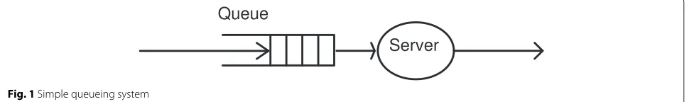
Let us consider a single buffer, as shown in Fig. 1, which is fed by a deterministic data arrival process and served by a single server. We assume that time is divided into slots with equal lengths, indexed by t ∈ {1, 2,. . .}. The total number of data packets that arrive at the buffer is
N. Starting fromt = 1, one packet arrives per time slot. Therefore, the last packet arrives att=N. For simplicity, we assume that the arrivals occur at the beginning of time slots. The server might be active or inactive in each time slot. When it is active, it can serve only one packet per time slot, where the service implies delivering the packet successfully to the destination. When it is inactive, no packet is served.
We note that if the server is active in each time slott∈ {1,. . .,N}, each packet will be served immediately after its arrival. In this case, there is no queue formed in the buffer and consequently, each packet experiences an over-all delay of one time slot, which is due to the time spent in the server. Accordingly, the packets will arrive in the des-tination at the beginning of time slotst ∈ {2,. . .,N+1}. However, if the server is inactive in the first time slot, the first packet has to wait in the buffer until time slot 2, to get served. Then, in time slot 2, when the second packet arrives, the server is busy with serving the first packet. Therefore, the second packet also experiences one slot delay in the queue and one slot delay in the server. In a similar manner, all the following packets incur the same queueing and service delays. In other words, the delayed operation of the server causes the nonzero queueing delay for the first packet, which is transferred to the subsequent packets as well.
Based on the above discussion, if the server is inactive in time slotx ∈ {1,. . .,N}, it adds one slot to the queueing delay (and the overall waiting time) of every packet arrived in slotxor afterward. In general, the packet which arrived in time slottwill experience a queueing delay ofntand will be delivered at time slott+nt+1, wherentindicates the number of slots before and includingtin which the server was inactive. It is clear that the cause of queue formation in such systems is the interruption in the operation of the server, which is translated to queueing delays of the data packets.
3 Effect of buffer-aided relaying on the
end-to-end packet delay
In this section, first we assume that data arrive in a deterministic manner and the availability of the chan-nels follows Bernoulli distribution and provide an insight on the end-to-end delay performance for conventional and buffer-aided relaying systems. Then, we analyti-cally derive the average end-to-end packet delay for
these systems, in the case that both the data arrival process and the availability of the channels follow Bernoulli distribution. Finally, we discuss general cases and present the intuitions about the end-to-end delay performance.
3.1 Relaying systems with deterministic data arrivals and Bernoulli channel conditions
Let us consider a relay network, with one source node, i.e., the BS, one relay node and one destination (or user) node, where the relay works based on the DF technique. It is assumed that there is no direct link between the BS and the user, and the transmissions are done only through the relay. There is only one channel in the system, which can be used for transmissions either from the BS to the relay or from the relay to the user. We usec1 andc2to
indicate the BS channel condition (for the link between the BS and relay) and relay channel condition (for the link between the relay and user), respectively. These variables can be either “Good” or “Bad”, meaning respectively that it is possible to transmit one or zero packet successfully on the corresponding channel. It is assumed that the channel conditions remain constant during each time slot but vary independently from one time slot to another. The prob-ability of being “Good” iss1ands2 for the BS and relay
channel conditions, respectively. We assume that each time slot is further divided into two subslots, where the BS and relay can transmit a packet in the first and second subslots, respectively. The reason for considering subslots is stated later in Remark 1.
Figure 2a shows the queueing model for a conventional relaying system, where the relay does not have buffer and therefore, if it receives a packet in a subslot, it has to trans-mit it immediately in the next subslot. The server 1 and server 2 indicate the wireless channel from the BS to relay and from the relay to user, respectively. On the other hand, Fig. 2b indicates a relaying network, where the relay has a buffer which allows it to store the data packets and trans-mit whenever its channel is good. In both of the figures, the rectangle enclosed around the servers is to abstract the overall serving behavior of the system from the time that the BS starts to transmit a data packet until it is delivered to the user. Note that the works in [8–11] in fact study the delay by considering only the time a packet spends inside this rectangle and do not take into account the waiting time in the BS queue, as they assume infinitely backlogged
buffer for the BS. However, in practice, the packets arrive finitely at the BS and experience a queueing delay before the transmission from the BS to the relay. Therefore, the overall waiting time of a packet in the relay network, which we also refer to as end-to-end delay, includes both its waiting time in the BS queue and the time it spends inside the aforementioned rectangle (i.e., the time period between the transmission at the BS and successful recep-tion at the destinarecep-tion). Note that the data arrivals at the BS might be due the packet generation in the BS itself, in which case the end-to-end packet delay might be referred to as “generation-to-delivery packet delay”; or it might be due to exogenous packet arrivals from an external network (e.g., the Internet), in which case the end-to-end packet delay might be referred to as “enter-to-exit packet delay” to specify the portion of the delay that a packet experi-ences since it enters the relay network until it exits it in the destination. In this paper, for simplicity, we will use the term “end-to-end” instead of “generation-to-delivery” or “enter-to-exit,” to specify the delay from the time that a packet arrives at the BS buffer until it is delivered to the destination.
In the following, we consider the data arrivals at the BS buffer as the deterministic process, withNpackets, men-tioned in the previous section. Taking the overall service behavior of the systems into account and based on the pre-vious section, we discuss the overall waiting time of data packets in both the conventional and buffer-aided relaying systems.
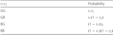
Table 1 shows the different states for the joint condi-tions of the BS and relay channels, in which G and B indicate “Good” and “Bad” conditions, respectively. We assume that a central scheduler at the relay has the CSI in each time slot, using the pilot signals transmitted by the BS and destination through error-free control channels at the beginning of that time slot. Based on the CSI and the buffering capability of relay, the scheduler decides about the packet transmissions over the links and notifies the BS and the destination accordingly. These are explained in detail in the following.
In the case of conventional relaying (no buffer in the relay), only whenc1c2=GG, the scheduler notifies the BS
to transmit a packet in the first subslot. Then, the relay for-wards the received packet to the destination in the second subslot. In the other three cases, i.e., when one or both of c1 andc2 are “Bad,” the packets remain in the BS buffer
Table 1Joint channel condition probabilities
c1c2 Probability
GG s1s2
GB s1(1−s2)
BG (1−s1)s2
BB (1−s1)(1−s2)
and are not transmitted. Therefore, conventional relay-ing serves the packets with the probability ofs = s1s2in
each time slot. Consequently, based on the discussions in the previous section, the overall server in the system is inactive with the probability of
unb=P(GB)+P(BG)+P(BB)=1−s=1−s1s2 (1)
where unb indicates the interruption probability for the overall server in the system without buffering at the relay. Considering this and the discussions in the previous section, in each time slot, the probability of “increase of one slot” in the overall waiting time of the packets present in that time slot or arrived after that isunb = 1−s1s2.
Here, the increase in the overall waiting time is due to the increase in the BS queueing delay of those packets.
Remark 1. Now, we explain the reason for considering subslots in each time slot. First note that the conventional relaying protocol stated above takes into account the CSI to decide about the packet transmission. This is reason-able as the CSI is assumed to be availreason-able at the scheduler, irrespective of exploiting buffer or not in the relay, and using it can prevent information loss in the case that suc-cessful delivery of packet is not possible (i.e., either one or both of the channel conditions are “Bad”). Second, since the channel conditions might vary from one time slot to another, the scheduler does not know what the CSI will be in the next time slot. Therefore, the CSI obtained in the beginning of a time slot can only be used to decide about the packet transmissions from the BS and relay during that time slot. Consequently, it is needed to have a sub-slot for the BS transmission and another one for the relay transmission, in conventional relaying. Note that alter-natively, one might refer to subslots as slots, in which case the channel conditions remain constant over two time slots and the BS transmissions happen in the odd-numbered slots and the relay transmissions happen in even-numbered slots.
Now consider the system where the relay has a buffer, but as before, the BS can only transmit in the first sub-slot and the relay can transmit in the second subsub-slot. We note that if the channel conditions are asBBin time slotx, similar to the system with conventional relaying, no trans-mission will be scheduled and therefore, there will be an increase of one slot in the overall waiting time of the pack-ets present in time slotxor arriving afterward. However, for the channel conditions asGBandBG, the case is dif-ferent. In order to clearly investigate these states, first we consider the following example:
scheduled and packet 1 will be transmitted from the BS to relay; but due to the “Bad” channel condition of relay, it will not be transmitted to the user in the second subslot and will be stored in the relay buffer. • In time slott=2, the channel conditions are asBG. Therefore, in the first subslot, there will not be any transmission from the BS to relay and the overall waiting time of the packets2,. . .,Nwill be increased byone slot. However, due to good condition of the relay channel, packet 1 will be transmitted from the buffer of the relay to the user in the second subslot.
In the above example, it is observed that packet 1 is served by the relay in time slott = 2 and therefore, it is delivered to the user in time slott = 3. This has become possible due to the queueing of that packet in the relay buffer. Note that with conventional relaying, however, in the above example, packet 1 would remain in the BS queue in both time slots t = 1 and t = 2, and the overall waiting time would increase bytwoslots forallthe pack-ets. Based on the above discussion and considering the nonzero probability of having channel conditions asGB andBGin two consecutive time slots, it can be concluded that ub < unb, where ub is the interruption probability of the overall server in the buffer-aided relaying system. In other words, the buffering capability in relay reduces the interruption probability of the overall server and con-sequently, it reduces the overall waiting time for the data packets. This is achieved due to the fact that the queue size in the BS is reduced, and the data packets transferred to the relay buffer enable the efficient use of the relay channel.
3.2 Relaying systems with Bernoulli data arrivals and channel conditions
Now, we consider the relaying networks where both data arrivals and channel conditions follow Bernoulli distribu-tion. We assume that in each time slot, the probability of one packet arrival at the BS buffer is a, and, as before,
the probability of “Good” channel condition for the BS and relay is equal tos1ands2, respectively. It is assumed
thata < s1s2 and therefore, the system queues are
sta-ble in the case of conventional and buffer-aided relaying [19, Chapter 2]. In the following, when we use subscriptsb andnbfor the variables, we refer to them in the case with buffering and without buffering at the relay, respectively.
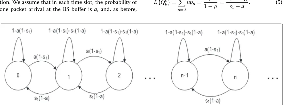
3.2.1 Buffer-aided relaying system
Based on [20, Section 7.5], Fig. 3 shows the Markov Chain model for the queue dynamics at the BS buffer for the buffer-aided relaying network, where each state represents the number of packets in the queue. Let pn, n ∈ {0, 1,· · · }denote the probability that in steady state, there are n packets in the BS queue. Note that due to equilibrium in the steady state, we have:
p0 = [1−a(1−s1)]p0+s1(1−a)p1,
pn = a(1−s1)pn−1+[1− {a(1−s1)+s1(1−a)}]pn +s1(1−a)pn+1,n=1, 2,· · ·
Based on the above equations, the probability of each state can be written as
pn=ρnp0, n=0, 1, 2,· · ·, (2)
Therefore, the expected number of packets in the BS queue can be expressed by
EQBb=
Note that when a new packet arrives at the BS buffer, its expected delay until completion of its service by the BS can be split into two parts. The first part is the expected time that it has to wait until the packets already in the queue are served, i.e.,EQBbETbB, whereETbB is the expected delay imposed due the service of each packet when it is in the head of queue. The second part is the expected time since the packet itself gets to the head of the queue until its service is completed, which is denoted asETbB∗. Therefore, the expected wait-ing time of a packet in the BS, EDBb, can be written as EDBb = EQBbETbB + ETbB∗. This is in fact the well known mean value approach which holds for queueing systems with memoryless data arrival processes [21, Section 4.3].
The interpretation of ETbB is as follows. The delay caused due the service of a packet in the head of the queue is 1 slot with the probability ofs1(this is in the case that
the BS channel is good at the time that the packet gets to the head of queue). It is(1+1)slots with the probability of (1−s1)s1,(2+1)slots with the probability of(1−s1)2s1,
(k+1)slots with the probability of(1−s1)ks1, and so on.
Therefore, the expected delay caused due to the service of a packet in the head of queue is given by
ETbB=s1+(1+1)(1−s1)s1+(2+1)(1−s1)2s1+ · · · Considering that the packet has reached the head of the queue, its delay until the departure from the BS is equal to 0.5 with the probability ofs1,(1+0.5)with the probability
of(1−s1)s1,(2+0.5)with the probability of(1−s1)2s1,
(k + 0.5) with the probability of (1 − s1)ks1, and so
on. Hence, the expected waiting time of the packet after reaching the head of the queue is
ETbB∗ = 0.5s1+(1+0.5)(1−s1)s1
Based on the above discussions, the expected total delay of a packet in the BS is equal to
We note that in each time slot, either one or zero packet departs the BS. Therefore, the packet departures from the BS can be modeled as a Bernoulli process. Due to the sta-bility of the queues, the data departure rate from the BS is equal to the data arrival rate in its buffer. Consequently, the probability that one packet departs the BS, or, equiv-alently, the probability that one packet arrives at the relay buffer, is equal toa. As a result, the average delay that a packet experiences in the relay can be computed in the similar manner as the average delay in the BS, which is expressed by
EDRb= 1−a s2−a−
0.5. (9)
Based on (8) and (9), the average waiting time of a packet in the buffer-aided relaying system is given by
E(Db)=E
Note that in the conventional relaying system, the BS can serve the packets in its buffer only when both its own channel and the relay channel are in good condition. Hence, the service probability for serving the BS buffer is s1s2. Considering that, the average number of packets in
the BS buffer can be obtained by replacings1in (5) with
s1s2, i.e.,E
QBnb= a(1−s1s2)
s1s2−a . Similarly, the average delay caused for a packet due to the service of each packet in front of it can be computed based on (6) and by using s1s2 instead ofs1, i.e., E
of the queue can be obtained, based on (7), asETnbB∗=
1−s1s2
s1s2 +0.5. Therefore, we have:
EDBnb=EQBnbETnbB+ETnbB∗= 1−a s1s2−a−
0.5.
(11)
On the other hand, when a packet arrives at the relay, it is immediately served without waiting in any buffer. Therefore, it only spends 0.5 of a slot in the relay, which is due to the service time in the relay. Consequently, we have:
EDRnb=0.5. (12)
Based on (11) and (12), the average waiting time of a packet in the conventional relaying system is given by
E(Dnb)=E
DBnb+EDRnb= 1−a s1s2−a
. (13)
In order to compare the delay performance of the con-ventional and buffer-aided relaying systems, Theorem 1 states and proves the main result of this subsection.
Theorem 1.Consider a relaying network where the data arrival process at the BS and the channel availability pro-cesses follow Bernoulli distribution and the packet arrival probability satisfies stability conditiona<s1s2. Then, the
average end-to-end packet delay in the buffer-aided relay-ing system is less than or equal to that in the conventional one. In other words, we have:
E(Db)≤E(Dnb), (14)
where the equality holds only in the case that the channels are always in “Good” condition, i.e.,s1=s2=1.
Proof.Please refer to the Appendix.
3.3 General relaying system
Now we consider a general scenario, where the data arrival and channel condition processes follow general distribu-tions, and are stationary and ergodic. We assume that the data arrivals and transmission rates have finite mean and variance. We use rbr(t), rrd(t), and rbd(t) to show the achievable transmission rate in time slot t between the BS and relay, the relay and destination, and the BS and destination, respectively. Without buffering, the BS needs to transmit to the relay in the first subslot, and then the relay has to forward it immediately in the next subslot. We know that in this case, the end-to-end achiev-able rate between the BS and the user is rbd(t) = 12 min{rbr(t),rrd(t)}. Therefore, the scheduler in the relay notifies the BS in the beginning of each time slot to trans-mit with a rate that can be supported by both of the links to lead to a successful reception at the destination. Due to
this, the transmission rate in each slot is limited by the link with the worst channel condition in that time slot.
However, when the relay has a buffer, there is no neces-sity for the immediate forwarding of the data and the abovementioned limitation is relaxed; therefore, the BS has the opportunity for transmitting continuously to the relay when the channel condition from the BS to relay is good. Then, the relay can store them in the buffer to transmit when the channel from the relay to user is good. Because of this, the buffering makes it possible to improve the system throughput as shown in [8–11]. Improvement in the throughput is equivalent to the improvement in the average end-to-end service rate of the data arrived at the BS buffer. In other words, the increase in the system throughput means that more data is transferred from the BS to the user, or equivalently, the same data is trans-ferred from the BS to the user in a less amount of time. Therefore, on average, packets experience lower end-to-end delay, i.e., the delay since their arrival at the BS until delivery to the destination.
Based on the above discussion, we make the conclu-sion as follows. Although buffer-aided relaying results in queueing delay in the relay, it also facilitates data trans-fer from the BS to the user and leads to a large reduction in the queueing delay at the BS. Therefore, the over-all effect is the improvement of the average end-to-end packet delay. In summary, we state this as follows.
Proposition.Using buffer in the relay improves the sys-tem throughput, and therefore, it reduces the average end-to-end packet delay.
Remark 2.We note that the given proposition is about
the average end-to-end packet delay. There might be
BS buffer nor in the relay buffer; in such a case, when a packet arrives at the BS, it can be immediately transmitted to the relay and then, the relay can immediately transmit it to the destination. This will take totally two subslots or equivalently one time slot.
In the previous subsection, even in the buffer-aided relaying system, we assumed that the BS and relay trans-missions are a priori scheduled to be done in the first and second subslots. In general, when buffering is exploited in the relay, each subslot can be used dynamically for the BS transmission or relay transmission, if there are data in their buffers. In this regard, a dynamic scheduling policy is required to stabilize the system queues. Specifically, in each subslot, this policy should decide on allocating the channel to the BS or relay such that the system queues remain bounded. For this, the well-known Max-Weight (MW) algorithm can be used, which has the largest sta-bility region [19, 22, 23]. MW aims at maximizing the weighted rates of the links, where the weight of a link is considered equal to the difference of the queue sizes at the two ends of the link. Note that due to the interdependence of the queue sizes and the scheduling decision in MW, it is highly intractable to derive the expressions for average queue sizes and delays under the MW policy. However, if the data arrival rate is inside the stability region (so it can be supported by the network capacity), it is guaran-teed that scheduling the links by MW policy will result in bounded average queue sizes and delays [19, 22, 23]. MW is an attractive scheduling policy for stabilizing the queues in buffer-aided relay networks as it works by utilizing just the instantaneous queue and channel state information (QCSI) and does not require information about the prob-ability distribution of packet arrival processes and channel states. Considering the abovementioned, we summarize the costs of buffer-aided relaying in the following remark.
Remark 3.Note that the costs for the improvements brought by buffer-aided relaying are the requirement for a memory to buffer data at the relay and the necessity for a scheduling algorithm to keep the queues stable.
Remark 4. It is worth noting that the proposition stated above can also be considered for the case of relay networks with more than two hops or more than one relays. For successful data transmission with conventional relaying in a multihop network, it is needed to have the chan-nel states of all the hops from the source to destination favorable during the transmission interval. However, with buffer-aided relaying, it is possible to use the channels more opportunistically. This is studied in [24], where it is shown that the outage (or unsuccessful packet recep-tion) is reduced in buffer-aided multihop networks, which is equivalent to improvement in throughput. Similarly, it is shown in [25] that in a network with multiple relays,
the system throughput is improved in buffer-aided relay-ing compared with the case without buffers at the relays. Therefore, based on those results and considering the queueing delays both in the source and the relay, we con-clude that the packets that are successfully received at the destination experience lower average end-to-end delay in the aforementioned relaying systems when buffering used in relays compared with the case without buffers in relays. The analysis for deriving the exact expressions of average end-to-end packet delay in these scenarios needs more investigation, as the effect of the relay selection policy should also be taken into account, and is an interesting research topic for future works.
4 Numerical results
To verify the presented discussions, we have conducted extensive Matlab simulations over 10,000 time slots and more. We have investigated the cases that the data arrival and channel condition processes follow Bernoulli distri-bution, as well as general cases with the settings of a practical system. We present the simulation results in the following.
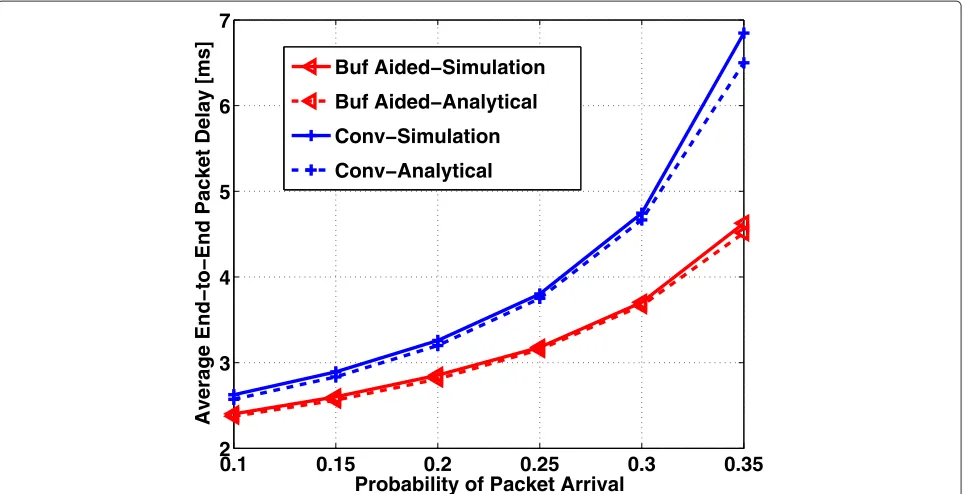
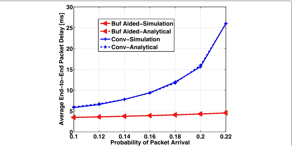
4.1 Bernoulli data arrivals and channel conditions In order to validate the analysis provided in Subsec-tion 3.2, in Figs. 4, 5, and 6, we present the average packet delay obtained from both the analytical expressions and the simulation. In each of these figures, we have fixed the values of s1 and s2 and have evaluated the effect of
increase in a on the average end-to-end packet delay. In order to maintain the stability of the system queues with both conventional and buffer-aided relaying, for each figure, we have considered a < s1s2. Figure 4 displays
the case with high probability for the good channel con-ditions at the BS and relay, i.e.,s1 = s2 = 0.9. It is clear
that the analytical results are quite close to the simulation ones. Moreover, the results confirm that the buffer-aided relaying has lower packet delays compared with the con-ventional relaying. As expected, both of the systems incur larger delay as the packet arrival probability increases. However, the delay in the conventional relaying system increases faster comparing with that in the buffer-aided relaying system.
Fig. 4Average end-to-end packet delay in the case of Bernoulli channel distribution withs1=s2=0.9
in the case of buffer-aided relaying, the BS can transmit to the relay even when the relay channel is bad. Then, the relay can buffer the received data and transmit in its subslots whenever its channel is good.
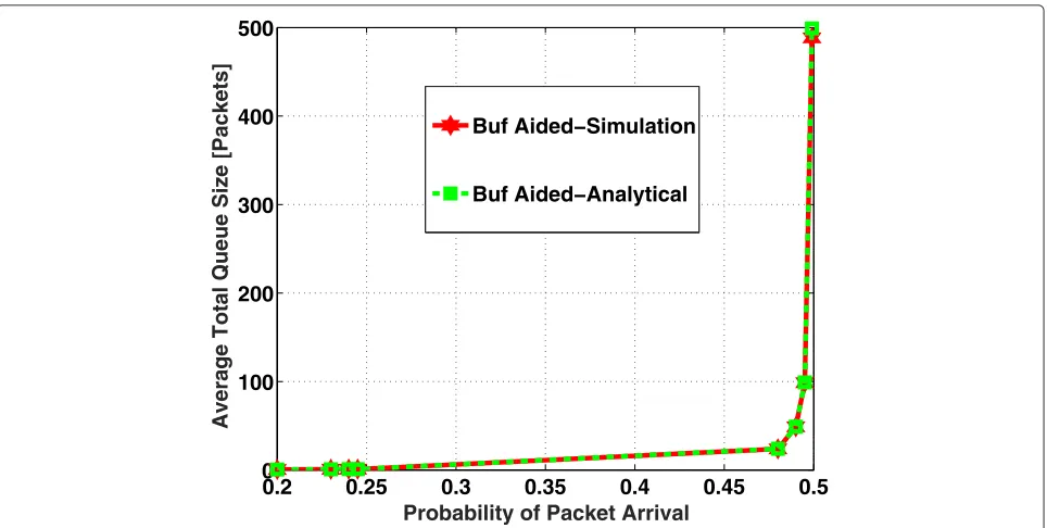
We have also conducted simulations to investigate the average total queue sizes when the packet arrival
probabilities get close to the stability region boundaries, in the case of s1 = 0.5,s2 = 0.5. We note that based
on [19, Chapter 2], the stability region boundary in con-ventional relaying is equal to s1s2 = 0.25 whereas it is
equal to min[s1,s2]= 0.5 in buffer-aided relaying. Also,
note that in conventional relaying, the total queue size is
Fig. 6Average end-to-end packet delay in the case of Bernoulli channel distribution withs1=s2=0.5
the BS queue size whereas in buffer-aided relaying, the total queue size is the sum of the BS queue size and relay queue size. Therefore, based on (5) and the discussions in Subsection 3.2, the mathematical expression of aver-age total queue size is a(s1s21−s1s2−a) in conventional relaying and a(s1−s1)
1−a + a(1−s2)
s2−a in buffer-aided relaying. The graphs for these equations as well as the results of simulations
are shown in Figs. 7 and 8. It is observed that the analyti-cal results are close to the simulation ones. Furthermore, Fig. 7 shows that the average total queue size in conven-tional relaying system increases rapidly when the packet arrival probability gets close to 0.25 (the stability region boundary for conventional relaying). This is due to the fact that the probability of having both the channel conditions
Fig. 8Average total queue size in buffer-aided relaying; the case of Bernoulli channel distribution withs1=s2=0.5 and the packet arrival probability close to the stability region boundary
“Good” (to be able to serve the packets in the BS queue in conventional relaying) is 0.25. When the data arrival prob-ability gets close to this value, more packets have to wait in the queue until they get to the head of buffer and get the chance to be transmitted. On the other hand, it is observed in Fig. 8 that the similar effect happens in buffer-aided relaying in considerably larger packet arrival probability, i.e., 0.5 (the stability region boundary for buffer-aided relaying), and before that, the average total queue size is small. This means that in the arrival probabilities larger than 0.25 in conventional relaying, when a packet arrives at the BS, it is expected to encounter an infinite queue size (and end-to-end delay) in its path to the destination. How-ever, even though in buffer-aided relaying, there are two buffers in the path of packets from the BS to the destina-tion, it is expected that the packets will encounter a finite total queue size (and end-to-end delay) before reaching the destination, as long as their arrival probability is less than 0.5.
4.2 General scenario
Note that the mathematical analysis presented in Subsection 3.2 and the numerical results shown in Subsection 4.1 are for Bernoulli data arrivals and channel conditions and provide an insight on the effect of using a buffer in relay on the end-to-end packet delay. In order to verify the discus-sions presented in Subsection 3.3 for general data arrival and channel condition processes, we consider a scenario
with more realistic settings. For this scenario, the simula-tion parameters are shown in Table 2. It is assumed that the channel fading is flat over the system bandwidth and constant during each time slot; however, it can vary from one slot to another. For the link between the relay and user, Rayleigh channel model is used, and for the link from the BS to relay, Rician channel model is used withκ fac-tor equal to 6 dB [26]. In the case of conventional relaying, the transmissions at the BS and relay are done in consecu-tive subslots. For buffer-aided relaying, we have used MW
Table 2Simulation parameters
Parameter name Setting
Cell radius 1000 m
Min UE-BS distance 50 m
BS antenna height 15 m
Relay antenna height 10 m
User antenna height 1.5 m
Relay distance from BS 1/2 cell radius
Pathloss model From [27]
Channel bandwidth 180 KHz
Time slot duration 1 ms
Noise power spectral density −174 dBm/Hz
Traffic model Poisson
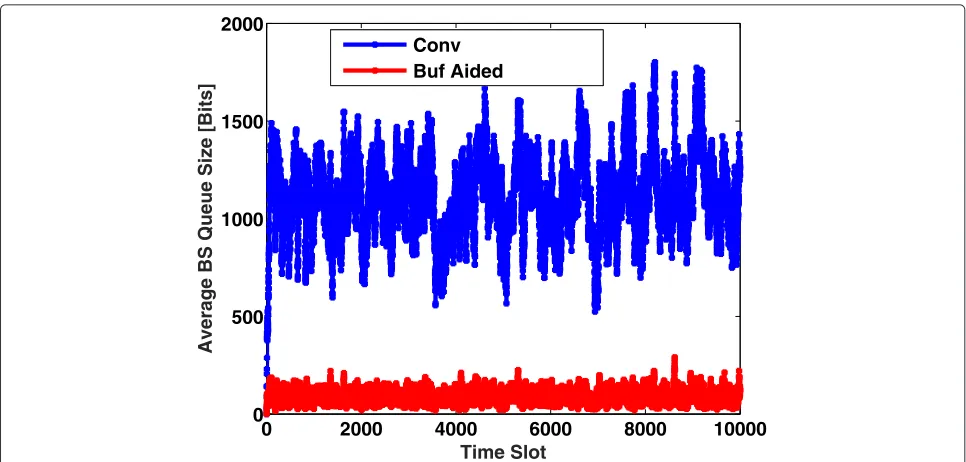
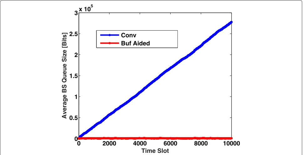
Fig. 9Average BS queue size over time at the arrival rate of 50 packets/second
policy [19, 22, 23] to decide in an adaptive way, about the transmission in each subslot, either from the BS or from the relay buffer. The simulations were conducted for 100 independent realizations of channel condition and data arrival processes, each over 10,000 time slots.
Figures 9 and 10 show the BS and relay average queue sizes over time, respectively, at the arrival rate of 50 packets/second. The average queue size is obtained by
taking the average of queue sizes over 100 simulations. It is observed that with buffer-aided relaying, although data are queued in the relay, the average BS queue size in each time slot is reduced significantly. This results in lower average end-to-end packet delays in buffer-aided relay-ing compared with the conventional relayrelay-ing, as shown in Fig. 11. In particular, in this scenario, the average end-to-end packet delays are 11 ms and 30 ms in buffer-aided
Fig. 11CDF of end-to-end packet delays at the arrival rate of 50 packets/second
and conventional relaying, respectively. Note that Fig. 11 indicates that in general, the average end-to-end packet delay is less in buffer-aided relaying. In other words, even though some packets might experience larger overall wait-ing time compared with the conventional relaywait-ing, most of the packets experience lower delay since their arrival
at the BS until delivery to the destination. Moreover, it is observed that the maximum end-to-end packet delay is less in the case of buffer-aided relaying.
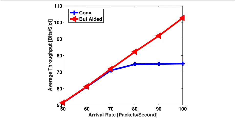
Next, we investigate the effect of increase in the packet arrival rate on the throughput and delay performance. It is observed in Fig. 12 that the conventional relaying is
Fig. 13Effect of packet arrival rate at the BS on the average end-to-end packet delay
able to support data arrival rates up to 60 packets/second, in which range it results in the average throughput equal to data arrival rate at the BS. However after that, due to low capacity, it starts to get saturated. This leads to queue instability and large end-to-end delays for packets, as shown in Fig. 13. In contrast, the buffer-aided relaying is able to provide the average throughput equal to the data
arrival rate, in all the packet arrival rates, and therefore leads to very low end-to-end packet delays.
In order to have a complete picture, we also present the system performance in the arrival rate of 100 packets/ second, in Figs. 14 and 15. Figure 14 shows that in conven-tional relaying, the average BS queue size grows unbounded; this is due to the low capacity of relaying channel which
Fig. 15Average relay queue size over time at the arrival rate of 100 packets/second
is unable to serve all the arrived data. This leads to large end-to-end packet delays as depicted in Fig. 16. On the other hand, as shown in Fig. 15, buffer-aided relaying leads to queueing in the relay buffer, which helps to uti-lize the channel variations efficiently. It allows to transfer the data from the BS buffer to relay buffer and from relay buffer to user, when the corresponding channels have
good conditions, and therefore leads to low end-to-end packet delays. In particular, in this scenario, the aver-age end-to-end packet delays are 20 ms and 1355 ms, respectively, in buffer-aided and conventional relaying.
The above results confirm that using buffer in relay improves the throughput as well as the average end-to-end packet delay in the system.
5 Conclusions
In this paper, we have studied the effect of buffering at the relay on the end-to-end delay performance. Through the discussions about queueing delay, we have explained the cause of delay in a simple queueing system. Based on that, we have provided an insight on the overall delay in the conventional and buffer-aided relaying networks. Moreover, for the case of Bernoulli data arrivals and channel conditions, we have proved analytically that the average packet delay is lower in buffer-aided relaying sys-tem compared with the conventional one. Finally, based on intuitive reasoning for general scenarios, we have con-cluded that employing buffer in the relay improves both the system’s throughput and average end-to-end packet delay. Using numerical results, we have verified our anal-ysis and discussions, and shown that using buffer in the relay leads to higher system throughput and lower average end-to-end packet delay.
Appendix
In order to prove that the buffer-aided relaying system incurs equal or lower delay compared with the conven-tional one, it is required to proveE(Dnb)−E(Db)≥0. To ranging the equations, we have
E(Dnb)−E(Db) =
Note that the packet arrival probability is nonzero and the stability condition holds, i.e., 0<a<s1s2. Sincesi ≤ 1,i = 1, 2, we have 0 < a < si,i = 1, 2, and s1i−−aa ≥ 1, i = 1, 2. Therefore, the first term in the right hand side of (16) is non-negative. Hence, it suffices to show
1−a
By canceling 1 − aand cross-multiplying in (17), we obtain
(s1−a) (s2−a)≥(1−a) (s1s2−a). (18)
After multiplying both sides out and canceling the com-mon terms of (18), we have
a(1−s1) (1−s2)≥0, (19)
which is always true sinces1≤1 ands2≤1.
Competing interests
The authors declare that they have no competing interests.
Acknowledgements
This work was supported by the Canadian Natural Sciences and Engineering Research Council through grants RGPIN-2014-06119 and RGPAS-462031-2014, and the National Natural Science Foundation of China through Grant No. 61271182. The work of Amr Mohamed was supported by NPRP 5-782-2-322 from the Qatar National Research Fund (a member of Qatar Foundation). The statements made herein are solely the responsibility of the authors.
Author details
1ECE Department, The University of British Columbia, Vancouver, Canada.2CSE Department, Qatar University, Doha, Qatar.
Received: 29 May 2015 Accepted: 12 November 2015
References
1. A Host-Madsen, J Zhang, Capacity bounds and power allocation for wireless relay channels. IEEE Trans. Inf. Theory.51(6), 2020–2040 (2005) 2. K Azarian, H El Gamal, P Schniter, On the achievable diversity-multiplexing
tradeoff in half-duplex cooperative channels. IEEE Trans. Inf. Theory.
51(12), 4152–4172 (2005)
3. C Hoymann, W Chen, J Montojo, A Golitschek, C Koutsimanis, X Shen, Relaying operation in 3GPP LTE: challenges and solutions. IEEE Commun. Mag.50(2), 156–162 (2012)
4. D Ng, R Schober, Cross-layer scheduling for OFDMA amplify-and-forward relay networks. IEEE Trans. Veh. Technol.59(3), 1443–1458 (2010) 5. Z Chang, T Ristaniemi, Z Niu, Radio resource allocation for collaborative
OFDMA relay networks with imperfect channel state information. IEEE Trans. Wirel. Commun.13(5), 2824–2835 (2014)
6. D Zhang, Y Wang, J Lu, Qos aware relay selection and subcarrier allocation in cooperative OFDMA systems. IEEE Commun. Lett.14, 294–296 (2010) 7. D Zhang, X Tao, J Lu, M Wang, Dynamic resource allocation for real-time services in cooperative OFDMA systems. IEEE Commun. Lett.15, 497–499 (2011)
8. B Xia, Y Fan, J Thompson, H Poor, Buffering in a three-node relay network. IEEE Trans. Wirel. Commun.7, 4492–4496 (2008)
9. N Mehta, V Sharma, G Bansal, Performance analysis of a cooperative system with rateless codes and buffered relays. IEEE Trans. Wirel. Commun.10, 2816–2840 (2011)
10. N Zlatanov, R Schober, Buffer-aided relaying with adaptive link selection-fixed and mixed rate transmission. IEEE Trans. Inf. Theory.59, 2816–2840 (2013)
11. N Zlatanov, A Ikhlef, T Islam, R Schober, Buffer-aided cooperative communications: opportunities and challenges. IEEE Commun. Mag.52, 146–153 (2014)
12. I Krikidis, T Charalambous, J Thompson, Buffer-aided relay selection for cooperative diversity systems without delay constraints. IEEE Trans. Wirel. Commun.11(5), 1957–1967 (2012)
13. T Islam, A Ikhlef, R Schober, V Bhargava, inProc. IEEE Global Telecommun. Conf.Multisource buffer-aided relay networks: Adaptive rate transmission, (2013), pp. 3577–3582
14. I Ahmed, A Ikhlef, R Schober, R Mallik, Power allocation for conventional and buffer-aided link adaptive relaying systems with energy harvesting nodes. IEEE Trans. Wirel. Commun.13(3), 1182–1195 (2014)
15. H Liu, P Popovski, E de Carvalho, Y Zhao, Sum-rate optimization in a two-way relay network with buffering. IEEE Commun. Lett.17(1), 95–98 (2013)
17. J Yang, Y Ran, S Chen, W Li, L Hanzo, Online source rate control for adaptive video streaming over HSPA and LTE-style variable bitrate downlink channels. To appear in IEEE Trans. Veh. Technol, 1–1 (2015) 18. R Zhu, J Yang, Buffer-aware adaptive resource allocation scheme in LTE
transmission systems. EURASIP J. Wirel. Commun. Netw, 1–16 (2015) 19. M Neely,Stochastic Network Optimization with Application to
Communication and Queueing Systems. (Morgan & Claypool, San Rafael, 2010)
20. F Gebali,Analysis of Computer and Communication Networks. (Springer, New York, 2008)
21. I Adan, J Resing, Queueing Systems. Online-Available: http://www.win. tue.nl/~iadan/queueing.pdf, Eindhoven University Netherlands (2015) 22. M Neely, E Modiano, C Rohrs, Dynamic power allocation and routing for
time varying wireless networks. IEEE J. Sel. Areas Commun., Special Issue on Wireless Ad-hoc Networks.23(1), 89–103 (2005)
23. L Georgiadis, M Neely, L Tassiulas, Resource allocation and cross-layer control in wireless networks. Foundation and Trends in Networking.1(1), 1–144 (2006)
24. C Dong, L Yang, L Hanzo, Performance analysis of
multihop-diversity-aided multihop links. IEEE Trans. Veh. Technol.61(6), 2504–2516 (2012)
25. A Ikhlef, DS Michalopoulos, R Schober, Max-max relay selection for relays with buffers. IEEE Trans. Wirel. Commun.11(3), 1124–1135 (2012) 26. M Jeruchim, P Balaban, K Shanmugan,Simulation of Communication
Systems: Modeling, Methodology and Techniques, 2nd edn. (Kluwer Academic, Dordrecht, 2000)
27. Tech. Rep 3GPP TR 25.996 V7.0.0 (2007-06), Spatial channel model for multiple input multiple output (MIMO) simulations. available at: http:// www.3gpp.org/DynaReport/25996.htm
Submit your manuscript to a
journal and benefi t from:
7Convenient online submission
7Rigorous peer review
7Immediate publication on acceptance
7Open access: articles freely available online
7High visibility within the fi eld
7Retaining the copyright to your article