R E S E A R C H
Open Access
Guidance control of vehicles based on
visual feedback via internet
Hou-Tsan Lee
Abstract
The proposed paper investigates the vehicle guidance control based on the visual information which is given by the webcam mounted on the vehicle. With the help of image processing techniques such as binarization, Canny edge detection method, and Hough transform, the road lines are thus identified, which means the drivable area can be defined. The proposed control scheme adopts a simple algorithm to guide the vehicle to run inside the drivable area within the road lines. The computation of defining drivable area and control algorithm is operated in a control center which connects the vehicle via WiFi wireless communication system. Similarly, the image information transmits back to the control center. Furthermore, the control center can not only monitor the vehicle inside some certain area but also control the vehicle dynamically in real time. To simplify the experimental setup, the drivable area is defined as the superhighway which allows only cars on the road. Two experimental results, one in a straight road and the other in a curved road, are given to demonstrate the effectiveness of the proposed guidance control system.
Keywords:Guidance control; Visual-based control; Vehicle control
1 Introduction
Many visual-based control system for vehicle had been developed to detect the dangerous area, obstacle edges, and road lines in literatures [1, 2]. One of the detecting methods is line detection which proposes the drivable area embraced by the road lines; to detect the lines thus defines the drivable area. On the other hand, line detec-tion also provides a comparison basis for safety driving to develop a warning system to avoid collisions [3–6]. Moreover, as wireless communication is being widely ap-plied nowadays, modern vehicles are usually equipped with the wireless communication components such as GPS, webcam, and WiFi modules. Furthermore, control methodologies for the locomotion and turning guidance of a vehicle were also developed to make automatic driv-ing feasible [7, 8].
In addition, during a long journey on the freeway, drivers easily fall asleep during their driving because of the road being usually straight and smooth in a period of time. The proposed vehicle guidance control system is developed based on the visual feedback images in front of the vehicle. When the images are transmitted
back to the control center, the image processing pro-gram first analyzes those images and identified the road lines; after that, the guidance control algorithm will gen-erate the control signals to keep the vehicle running in-side the drivable area, which means to stay within the road lines. Then, the control center will send the control signals to the vehicle to guide the vehicle how to move.
In the image processing process, after binarization, Canny edge detection process and Hough transform are applied to identify the edges of the road lines and plot them on the display. In order to easily calculate the dis-tances between vehicle and road lines, the position of the webcam is mounted on the center of the vehicle with a certain height. By using a simple feedback control technique, the vehicle automatically modifies its yaw angle to navigate the vehicle to move on the right trail inside the drivable area. The proposed visual-based guid-ance control system also provides two experimental re-sults to validate the performance. One is on the straight road and the other is on the curved road. Both experi-mental results are satisfactory. Recently, 3D techniques were taken into the design for vehicle guidance to im-prove the performance of vehicle control with satisfac-tory performance [8, 9]. On the other hand, the real time issue also played an important role due to the rapid Correspondence:[email protected]
Department of Information Technology, Takming University of Science and Technology, Taipei, Taiwan
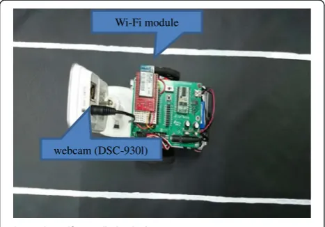
nicate with the control center and a webcam (DCS-9301) mounted on the center of the vehicle to acquire the im-ages of the road in front of the vehicle [11]. The control board of the vehicle is a combination of a WiFi module (RN-131C), a BS2 microprocessor, and some circuit to provide the necessary signals for driving two DC motors to rotate the wheels of the vehicle. The webcam is also equipped with a WiFi module to provide image informa-tion to the control center via wireless WiFi communica-tion system in real time.
2.2 Overall system architecture
The sketch of the overall system is shown in Fig. 2. The overall system is composed of a control center and a ve-hicle equipped with WiFi module and webcam as men-tioned in subsection 2.1. They are all connected via WiFi system, the IEEE 802.11 g, in the proposed system. The webcam sends the image information to the control cen-ter via Incen-ternet (or some wireless network) same as how the control center sends the control signals to the WiFi module on the vehicle to drive the vehicle. On the other hand, the control center can also release the control pri-ority back to the driver if needed such as engaging an intersection, losing connection signals between control center and the controlled vehicle, or the driver’s request. In the proposed control scheme, the driver always has high priority than the control center.
2.3 Control process of overall system
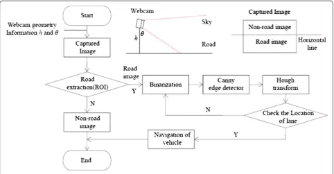
The road lines are first detected and then drawn on the images transmitted from the webcam by those pre-mentioned image processing methods as shown in the upper part of Fig. 3. The image sent back to the control center first filters out the information useless, e.g., the sky and the lower part of the road.
After binarization of the original image, Canny detec-tion technique and Hough transform are being applied; the road lines thus are being detected [12]. Because the edge lines are multiple, some of them should be elimi-nated such as those with strange angles. Therefore, the proposed program erases some useless lines. After these processes, the road lines are thus concluded (left: red line, right: green line). The computer program also marks the center spot of the image (blue line) regarded as the center of the vehicle. Then, the distances between the center and the right line and left line are simultan-eously calculated and shown on the images. During the running of the vehicle, the proposed control scheme maintains the same constant distances of the left and right as possible which leads the vehicle to run along the road and inside the drivable area. This method is effect-ive especially not only on the straight line but also on the curved line with satisfactory performance in the ex-perimental results. However, the speed of the vehicle will be limited within a multi-curve path because the trans-mission time delay is crucial in the rapid changing guid-ance as well as manual driving. The result of the road line detection is illustrated in Fig. 4.
3 Guidance control
The lower part of Fig. 3 gives a block diagram concept of the control process. The navigation of the vehicle de-pends on a simple algorithm as follows. The control
Wi-Fi module
webcam (DSC-930l)
Fig. 1The self-propelled vehicle
WiFi mode
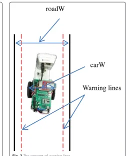
algorithm of the proposed guidance law is shown in Fig. 5. The basic control concept of the proposed control scheme is based on keeping the vehicle inside the driv-able region which is decided by the road line detection. Beside the technique of road detection, guidance control scheme according to vanish point is also a popular ap-proach [13, 14]. The methods developed based on the vanish point are especially effective in parallel edges. In the proposed control scheme, the techniques deduced from the vanish point are not concerned, but a more simple method of comparison is developed. First of all, the warning lines are first decided based on the different
conditions such as speed, road width, and car width. The proposed design chooses warning lines as half of the width of the remaining space of the road as shown in Fig. 5. After that, the image feedback is analyzed and the variables are thus decided as shown in Fig. 4. The al-gorithm is shown in Fig. 5. Based on the guidance law as shown also in Fig. 5, the control signals are acquired and sent to the vehicle to vary the direction in order to keep the trail within the drivable area. Both the signals’ packets of control and images are bidirectional trans-mitted via Internet with the help of WiFi modules. The control center and the vehicle exchange information as a client-server mode in the wireless network is shown in Fig. 5.
In Fig. 5, the control process only activates if the con-nection between control center and the vehicle is suc-cessful. Otherwise, the control priority remains in the driver. As the algorithm begins, the vehicle will try to keep its position on the center of the road. In order to respond to the error quicker, a set of warning lines are thus designed to keep the vehicle inside the drivable area. The design of the warning lines can compromise the time delay during the transmission of the newest control signals. The abovementioned algorithm includes the guidance law, server algorithm, and the client algo-rithm to assure successful guidance.
Figure 6 shows the diagram of the feedback control of the vehicle, in which the reference signal Δdepends on the different conditions, e.g., the car in the next lane and sudden appearance of objects. The referenceΔis zero in Fig. 3The sketch of the control process
the proposed system to guide the vehicle to move along the central line of the road. To deal with the transmission time delay, the proposed system provides a set of warning lines inside the real road lines as shown in Fig. 7 to pre-vent vehicle from crossing the lines due to some slight delay of the control signals when deviation happens. The
algorithm in Fig. 5 is also involved with the concept of the warning lines.
Actually, the warning lines do not appear in the real image. The warning lines were only designed in the pro-gram for guidance control of the vehicle.
4 Experimental results
The experimental setup comprises a notebook computer as the control center, an access point as the base station for infrastructure mode, a vehicle, and a paper-made road. Figure 8 demonstrates the physical experimental setup of the proposed control system.
Fig. 6The feedback control of the vehicle Fig. 5The algorithm of guidance law
carW
Warning lines
Two experiments are conducted based on the proposed visual-based vehicle guidance control system. They are de-scribed as follows.
4.1 Straight lane case
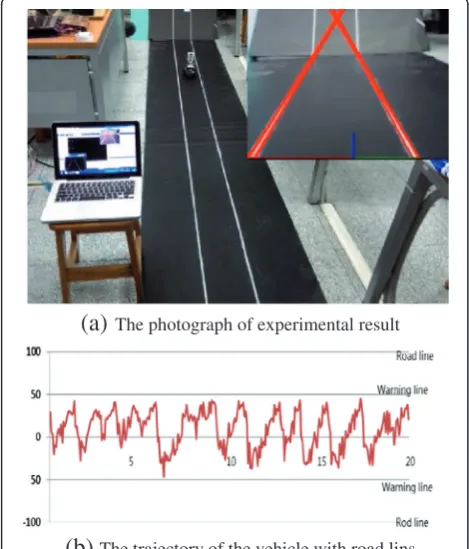
Figure 9 shows the experimental result of the straight lane case. The line detection is displayed on the upper right part of Fig. 9a in red. The blue line indicates the center of the vehicle and the moving direction. The guidance control law leads the vehicle to go along the road and keep the vehicle inside the road lines. Figure 9b gives the trajectory of the vehicle during [0 20] s. The lines are defined as [−100 100], the center is defined as
0, and the warning lines are defined as [−50 50] to show the effectiveness of the proposed guidance law. Because the vehicle (self-propelled BB car) has some hardware deviation which cannot be calibrated, the vehicle always slightly slides left. Therefore, the trajectories of both Figs. 9b and 10b show some oscillations, but the pro-posed control scheme is also effective. On the other hand, the response time between visual feedback to the response on the vehicle is about 0.9 s (the average time of 100 times) with about 14 image feedback in 1 s.
4.2 Curved lane case
The same as the previous straight lane guidance, the ex-perimental result of curved lane guidance is shown in Fig. 10. The lower right part of the Fig. 10a shows the image of the webcam after line detection. The road lines are marked in red as well as the center of the vehicle is marked in blue. The speed of the vehicle is a little bit slow in the curved lane guidance due to the safety concern. The lines are defined as [−100 100], the center is defined as 0, and the warning lines are defined as [−50 50] to show the effectiveness of the proposed guidance law in Fig. 10b. In the curved road case, the trajectory of the vehicle is trembler than the trajectory in the straight road case. Fig. 8The experimental setup of the proposed system
(a)
The photograph of experimental result(b)
The trajectory of the vehicle with road linsFig. 9Experimental result of straight lane guidance.aPhotograph of the experimental result.bThe trajectory of the vehicle with road lines
(a)
The photograph of experimental result(b)
The trajectory of the vehicle with road linsthe drivable area. Two experimental results are also given to show effectiveness of the proposed visual-based vehicle guidance control system with satisfactory performance.
Competing interests
The authors declare that they have no competing interests.
Acknowledgements
The author would like to thank Jhe-Yu Guan, Wei-Liang Chen, Shao-Hsuan Hsu, Hao-Hsiang Yang, and Li-Wei Liu for their help in the experimental setup and implementation.
Received: 1 September 2014 Accepted: 19 May 2015
References
1. A Broggi, M Bertozzi, A Fascioli, C Guarino Lo Bianco, A Piazzi, Visual perception of obstacles and vehicles for platooning. IEEE Trans. Intell. Transp. Syst.1(3), 164–176 (2000)
2. AG Mohapatra, Computer vision based smart lane departure warning system for vehicle dynamics control. Sens. Transducers. J.132(9), 122–135 (2011) 3. B Yu, W Zhang, Y Cai, A lane departure warning system based on machine
vision, in 2008 IEEE Pacific-Asia Workshop Computational Intelligence Industrial Application. 1, 197–201 (2008). doi:10.1109/PACIIA.2008.142
4. OO Khalifa, R Islam, A Am Assidi, A-H Abdullah, S Khan, Vision based road lane de-tection system for vehicles guidance. Aust. J. Basic Appl. Sci.5(5), 728–738 (2011) 5. W Li, Human-like driving for autonomous vehicles using vision-based road
curvature modeling. Int. J. Hybrid. Inform. Technol.6(5), 103–116 (2013). doi:10.14257/ijhit.2013.6.5.10
6. C Kreucher, S Lakshmanan, K Kluge,A driver warning system Based on the LOIS Lane Detection Algorithm. Proc IEEE Int Conference on Intelligent Vehicles, 1998, pp. 17–22
7. ED Dickmanns, N Muller, Scene recognition and navigation capabilities for lane changes and turns in vision-based vehicle guidance. Control. Eng. Pract.4(5), 589–599 (1999). doi:10.1016/0967-0661(96)00041-X
8. KR Liewellyn, Visual guidance of locomotion. J. Exp. Psychol.91(2), 245–261 (1971). doi:10.1037/h0031788
9. ED Dickmanns, T Christians, Relative 3D-state estimation for autonomous visual guidance of road vehicle. Robot. Auton. Syst.7(2–3), 113–123 (1991). doi:10.1016/0921-8890(91)90036-K
10. Z Hu, K Uchimura,Real-time data fusion on tracking camera pose for direct visual guidance. 2004 IEEE Intelligent Vehicle Symposium, 2004, pp. 842–847. doi:10.1109/VS.2004.1336494
11. H-T Lee, W-C Lin, C-H Huang, Wireless indoor surveillance robot with a self-propelled patrolling vehicle. J. Robotics.2011, 9 (2011).
doi:10.1155/2011/197105
12. R Joˇsth, M Dubská, A Herout, J Havel, Real-time line detection using accelerated high-resolution Hough transform, Proc 17th Scandinavian Conference Image. Analysis6688, 784–793 (2011). doi:10.1007/978-3-642-21227-7_73 13. B Alberto, M Bertozzi, A Fascioli, C Guarino, L Bianco, A Piazzi, The Argo
autonomous vehicle’s vision and control systems. Int. J. Intelligent. Control. Syst.3(4), 409–441 (1999)
14. H Cheng, N Zheng, C Sun, H van de Wetering, Vanishing point and gabor feature based multi-resolution on-road vehicle detection. Proc Third Int Conference Advances Neural Networks3973, 46–51 (2006). doi:10.1007/ 11760191_7
Submit your manuscript to a
journal and benefi t from:
7Convenient online submission 7Rigorous peer review
7Immediate publication on acceptance 7Open access: articles freely available online 7High visibility within the fi eld
7Retaining the copyright to your article