R E S E A R C H
Open Access
Performance of opportunistic fixed-beam spatial
multiplexing in OFDMA uplink
Juha Ylitalo
Abstract
Adaptive spatial multiplexing (SM) Multiple Input Multiple Output (MIMO) techniques enhance the spectral efficiency of wideband wireless communications in favorable radio channel conditions. In this study, we show the benefits of combining a traditional fixed-beam scheme and multiuser opportunistic radio resource allocation in space-time-frequency domains. This combining is feasible in wideband Orthogonal Frequency Domain Multiple Access (OFDMA) systems such as the Universal Mobile Telecommunications System (UMTS) Long Term Evolution (LTE). This study brings novel knowledge which indicates that an orthogonal fixed beam approach benefits from opportunistic radio resource allocation clearly more than a conventional antenna domain approach in frequency-selective radio channels. It was found out that the fixed beam radio link performance is enhanced in wideband adaptive radio links due to the fact that orthogonal beams reduce correlation between the MIMO channels in the allocated sub-bands. Moreover, beamforming gains bring higher Eigenvalues of the MIMO channel matrix in the opportunistically selected sub-bands. It is shown that the fixed beam deployment changes the distribution of the MIMO channel correlation values and Eigenvalues in a manner which enhances opportunistic multiuser gains in wideband time-frequency-selective MIMO radio channels. Simulation results with 2 × 2 spatial multiplexing in an OFDMA uplink indicate that the proposed beam domain scheme gives up to 80% data throughput gain over the corresponding antenna domain scheme in a pedestrian microcell environment.
Keywords:Wireless mobile communications; OFDMA waveform; MIMO; Spatial multiplexing; Adaptive radio link; Beamforming; Fixed beams
Introduction
The Multiple Input Multiple Output (MIMO) techniques offer either a high degree of diversity to combat path loss and fading or a high multiplexing gain for enhanced peak data rates and improved spectral efficiency [1-7]. With N transmitter (TX) and M receiver (RX) antennas, the max-imum diversity gain is N × M, and the maxmax-imum spatial multiplexing gain is min {N, M}. The two basic MIMO approaches include space-time coding for maximizing the transmit diversity gain and parallel transmission of inde-pendent data streams for maximizing the multiplexing gain (spatial multiplexing). Switching between spatial multiplex-ing and transmit diversity can be deployed in a simple man-ner [6]. Obtaining both gains simultaneously requires that each of the parallel data streams in MIMO transmission is coded over all the TX antennas. A general approach is to
apply linear dispersion coding [5,8]. One obvious way to code the parallel data streams over multiple antennas is beamforming, for example the fixed beam technique.
Traditional transmit beamforming is a robust technique which spatially focuses power towards the targeted user and reduces interference to other directions. It requires TX antenna separation of one half of carrier wavelength, approximately, and works best in spatially correlated radio channels [9]. This is interesting also from a viewpoint of wideband Orthogonal Frequency Domain Multiple Access (OFDMA) radios since the user-specific radio channel coefficients seen by the base stations are spatially correlated in the allocated sub-bands of an individual mobile user. Thus frequency selectivity of the radio channel can be deployed for allocating each user the best sub-bands. These sub-bands have relatively small angle spread of propagation paths which leads to high spatial correlation even in microcells, in which the root mean square (RMS) angle spread per propagation path (sub-band) is typically
Correspondence:[email protected]
Elektrobit Wireless Communications Ltd. and University of Oulu, Tutkijantie 8, 90590 Oulu, Finland
in the range of 5° [10]. Therefore, a wideband OFDMA base station is capable of utilizing the high correlation of individual user specific propagation paths and applying beamforming for the selected sub-bands.
Beamforming combined with spatial multiplexing offers one approach to realize full diversity full rate data trans-mission [11]. As a practical example, the dual-stream closed loop transmit diversity of the 3GPP Universal Mo-bile Telecommunications System (UMTS) [12] represents an approach, in which each of the two data streams is transmitted in a digital precoding (beamforming) mode from both of the TX antennas. Feedback information from the user terminal are used to select predetermined precod-ing antenna weight vectors. The benefits of combinprecod-ing the fixed beam technique with multiuser spatial multiplexing have been studied from an information theoretic viewpoint in [13]. A corresponding system simulation study shows that the fixed beam approach is promising especially for outdoor and wide area network deployment [14]. These re-ports focus on spatial separation of users and do not take into account the impact of opportunistic radio resource al-location in the frequency domain.
As discussed, e.g., in [9], the benefits of spatial multi-plexing MIMO are subject to many assumptions. A cru-cial assumption is that parallel MIMO channels have adequately low cross-correlation and high enough signal to noise ratio (SNR) levels, i.e., high Eigenvalues. This indicates that spatial multiplexing has to be employed adaptively during the time periods when the MIMO radio channel is in a favorable state. In a multiuser scenario, this leads inherently to the approach of opportunistic beam-forming [15] in which all the TX resources are given in a time-multiplexed manner to those users which possess a good radio channel state. Significant multiuser diversity gain is achieved in fading channels. This gain is further pronounced in wideband systems which enable radio resource allocation also in the frequency domain.
As an example of a state-of-the-art technology, the UMTS Long Term Evolution (LTE) adapts the transmis-sion MIMO mode to the prevailing radio channel condi-tions based on the feedback information from the mobile terminal [16]. Based on the feedback from multiple users, the base station attempts to allocate the scheduled users those sub-bands which enable spatial multiplexing and which maximize total system throughput. The reporting interval is 1 ms at shortest which enables accurate adapta-tion to the fading radio channel especially in microcells with slow user terminal velocities (0 to 15 km/h) [17].
The target of this study is to evaluate the performance of opportunistic sub-band-based OFDMA data communication in a fixed beam domain compared to that of in the trad-itional antenna domain. The opportunism is achieved via adaptive data packet allocation techniques in space (beam), time, and frequency domains. The main contribution of this
paper is to show that an orthogonal fixed beam approach benefits from opportunistic radio resource allocation clearly more than a conventional antenna domain approach in frequency-selective radio channels. The radio link perform-ance of a fixed beam base station is studied using as realistic simulation parameters as possible including a well-defined microcell radio channel environment and practical base sta-tion antenna/beam patterns. To the best of author’s know-ledge, there is a lack of reports studying in detail the benefits of combining a traditional fixed-beam scheme and oppor-tunistic wideband radio resource allocation in space-time-frequency domains.
The paper is organized as follows. In the‘System model’ section, the system model is presented. The‘Spatial correl-ation of MIMO channels’section studies the correlation of the antenna and beam domain signals. The adaptive algorithm is reviewed in the‘OFDMA simulation model’ section, and the ‘Simulation results’section presents the simulation results.
System model
The concept under the current study assumes the baseline LTE 2 × 2 spatial multiplexing (SM) technique with the linear minimum mean square error (MMSE) receiver [16]. The MMSE receiver is based on optimum combining of antenna signals in the presence of interference. It is often referred as a Wiener solution and its antenna weight vectorwhas a form [18]
wMMSE¼R−xx1v ð1Þ
in which vis the array response vector of the desired signal,Rxxis the covariance matrix of the received signal
(includes contributions from the desired signal, interfer-ence, and additive Gaussian noise), and * denotes conju-gate transpose. A basic 2 × 2 MIMO receiver applies interference suppression in a way that first the stronger data layer is detected using the MMSE and thereafter the detected data layer is canceled from the received data before detecting the second layer by ordinary max-imal ratio combining [1].
Approach
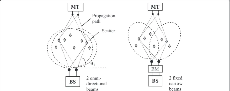
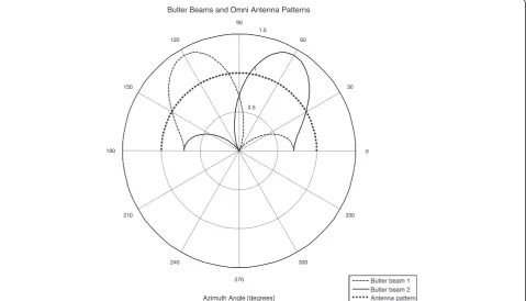
Figure 1 shows the principle of the proposed 2 × 2 MIMO scheme with fixed narrow beams at the base station (BS; on the right) compared to a traditional MIMO approach with omnidirectional BS antenna pat-terns on the left. In both cases, the mobile terminals (MT) apply omnidirectional antenna patterns. In the antenna domain, every propagation path has ideally the same complex antenna gain regardless of the path azimuth direction. In the beam domain, every path has a different complex gain depending on its direction. The antenna domain MIMO scheme relies on spatial diversity created by the MT and BS antenna positions and the geometric distribution of the scatters while the fixed beam scheme employs beamforming gain and an-gular diversity of the propagation paths. The fixed beams of the proposed scheme can be created by an analog beamformer, e.g., the Butler matrix (BM), which transforms the antenna domain signals into an orthog-onal beam domain (Figure 2).
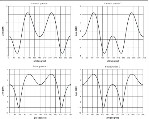
In practice, the beam patterns are not ideal due to, e.g., mutual coupling between antennas. These effects are illus-trated in Figure 3 which shows realistically simulated beam patterns that are applied in the performance evaluation of this study. The patterns were obtained using a commercial radio frequency (RF) simulation tool [19] with the assump-tion that monopole antennas are located at a spatial separ-ation of 0.5 wavelength of the carrier frequency. The coupling effects cause antenna gain fluctuation of almost 5 dB in antenna domain (plots on top) while the ratio of the maximum beam gain to the beam pattern null is more than 12 dB in the beam domain (plots at the bottom).
The generic narrowband MIMO signal model can be represented as a complex baseband vector notation:
y¼Hxþn; ð2Þ
in which y is the received N × 1 signal vector, x the transmitted M × 1 signal vector, n denotes the N × 1
white Gaussian noise vector, and H the N × M radio
channel matrix. In this study, we consider a wideband MIMO model which takes into account the time-variant directional path radio channel. Assuming multi-antenna arrays with omnidirectional multi-antenna patterns at both the BS and the MT, the signal transmitted by TX
antenna m and received by the RX antenna n can be
written as a sum of individual propagation path contri-butions [20]:
yn;mð Þ ¼t
XK
k¼1
GRX;n;θkGTX;m;φkβk
e−j2πðn−1Þdsinθk=λ e−j2πðm−1Þdsinφk=λ
⋅ ej2πðfdcosγkt−αkÞ x
mð Þt δðt−τkÞ þn tð Þ; ð3Þ
wherexm(t) is the transmitted signal from antennam,yn,
m(t) is the corresponding received signal at antenna n,βk andτkare the magnitude and the delay of propagation path k,θkandϕkare the directions of the pathkat RX and TX antenna arrays with respect to the antenna array normal,λ denotes the wavelength of the carrier frequency,αkis the initial phase angle of pathk,fddenotes the Doppler shift corresponding to maximum MT velocity,γkis the angle of the scatter atkth propagation path with respect to the MT velocity vector, and δ is the Dirac delta function. The
antenna spacingdand the actual TX and RX antenna pat-terns (directional gains GRX;n;θk; GTX;m;φk) play a signifi-cant role in the spatial correlation properties of the MIMO scheme. The directional gains may contain individual an-tenna patterns (in anan-tenna domain) or, e.g., the Butler beam patterns in beam domain. In the following, we assume that the Butler Matrix is applied at the BS only so that for each RX branch n the corresponding gain pattern follows the corresponding Butler beam pattern of Figure 3.
Using matrix notation, the received orthogonal beam domain signal vectoryb(t) is obtained from the RX antenna domain signal vectorya(t) by a matrix multiplication:
ybð Þ ¼t B yað Þt ; ð4Þ
in which B denotes the BM. In case of 2 × 2 MIMO, the normalized BM has the form:
B¼ 1=pffiffiffi2 − j=pffiffiffi2
1=pffiffiffi2 þ j=pffiffiffi2
: ð5Þ
Thus the two antenna domain signals can be transformed into the beam domain by multiplying them by the two row vectors of (5). This is achieved in the above mentioned RF simulation tool by ±90° phase shifts to provide the beam patterns of Figure 3.
Radio channel model
The 3GPP spatial channel model (SCM) [10] was adopted in this study using its MATLAB™ implementation from the WINNER project [21]. The urban microcell environ-mental model was applied since it is most feasible for high data rate MIMO applications due to its wide angular spread (AS) of propagation paths and relatively short dis-tances between users and the base station. This guarantees a low degree of spatial correlation and a strong signal level at a receiver. The microcell model (‘Pedestrian B’in [10]) is designed for a 5 MHz bandwidth and it consists of six delay taps within a delay range of 3.7 μs which brings a good degree of frequency selectivity. Each delay tap consists of 20 sub-paths with fixed angular directions in order to create the desired Laplace distributed power azimuth spectrum. In the Pedestrian B model, the total RMS angular spread at BS is 19° whereas the per-path AS is 5°. As said, frequency selectivity enables opportunistic use of those frequency sub-bands which are most feasible to spatial multiplexing MIMO.
The MIMO radio channel characteristics are determined by the scatter positions and properties as well as the TX and RX antenna constellations and orientations. If we con-sider an OFDMA user assignment into a sub-band, we can assume that the allocated band represents a narrowband 2 × 2 MIMO system with flat fading. The corresponding radio channel matrixH(t,τ) is composed of four complex
0.5 1
1.5
30
210
60
240
90
270 120
300 150
330
180 0
Butler Beams and Omni Antenna Patterns
Azimuth Angle [degrees]
Butler beam 1 Butler beam 2 Antenna pattern
elements each of which defines the channel impulse response between different TX and RX antenna pairs. It can be represented as
Hð Þ ¼t;τ hh1;1ð Þt;τ h1;2ð Þt;τ
2;1ð Þt;τ h2;2ð Þt;τ
; ð6Þ
in which the first and second rows represent the chan-nel impulse responses from TX antenna 1 and from TX antenna 2 to RX antennas, respectively. The narrowband model can be applied here due to the fact that the band-width of a single resource block (RB) allocation can be relatively small (in LTE, a single RB takes 180 kHz). For the best MIMO performance, the channel matrix H(t,τ) should show large Eigenvalues and low correlation between the MIMO channels.
Spatial correlation of MIMO channels
Spatial correlation between different antenna signals plays a significant role in MIMO performance. The degree of correlation is determined by the radio channel characteris-tics, the antenna constellation and orientation, as well as the antenna beam patterns. It has been shown by experi-ments that a simple stochastic MIMO model based on the Kronecker product of the spatial correlation matrices of TX and the RX antennas, respectively, models well the actual propagation environments [22]:
RMIMO¼RBS⊗ RMT; ð7Þ
in which RBS and RMT are the spatial correlation
matrices at the base station and the mobile terminal and
⊗denotes the Kronecker product. As (7) indicates the
Antenna pattern 1 Antenna pattern 2
Beam pattern 1 Beam pattern 2
phi [degree]
Gain [dBi]
Gain [dBi]
phi [degree] -4
-3 -2 -1 0 1 2
0 30 60 90 120 150 180 210 240 270 300 330 360 -4 -3 -2 -1 0 1 2
Gain [dBi]
0 30 60 90 120 150 180 210 240 270 300 330 360
phi [degree] phi [degree]
0 30 60 90 120 150 180 210 240 270 300 330 360 0 30 60 90 120 150 180 210 240 270 300 330 360 -12
-10 -8 -6 -4 -2 0 2 4
Gain [dBi]
-12 -10 -8 -6 -4 -2 0 2 4
MIMO correlation matrix can be composed of inde-pendent BS and MT spatial correlation matrices. At both ends, the spatial correlation is determined by the power azimuth spread of the propagation paths impin-ging at the antenna array. The spatial correlation can be expressed also as channel covariance C, which can be given as an analytical form [23]:
Ckl;mn¼
in which indexes k,m and l,n denote an RX and TX
antenna pair in a 2 × 2 MIMO system, αpis the gain of propagation pathpwith angle of departureΩt,pand angle of arrivalΩr,p, and * refers to complex conjugation. The radiation patterns of the two RX and TX antennas are given byer,k, er,m, et,l, andet,n, respectively. It is assumed that each propagation path is modeled as a plane wave. As (8) shows the spatial correlation can be evaluated analytic-ally for different angular distributions of the power azi-muth spread (PAS) of propagation paths as long as the antenna radiation patterns are known. It is noted that (8) takes only the powers of the propagation paths into account which means that all the possible phase shifts of the propagation paths are averaged out. Thus it gives the expected difference of spatial correlation between the antenna and beam domain approaches. It does not reveal though the instantaneous characteristics in radio channel states which can be deployed in the opportunistic data transmission scheme. What comes to PAS, radio channel measurements have indicated that the impinging signal path directions follow Gaussian distribution in azimuth while the PAS is Laplace distributed [24,25]. In the follow-ing, we take the approach of the 3GPP SCM channel model [10] implementation in which the PAS of propaga-tion paths is modeled as Laplace distributed [21,26]. More specifically, the desired PAS is obtained by 20 equal power propagation paths whose directions are adjusted in a way that the Laplace angular spread properties are obtained. This approach allows a straightforward numerical solution to (8) and, therefore, can be applied both in semi-analytical evaluation and in simulations. It is noted that we are interested in the spatial correlation at the BS which employs the fixed beam approach. Since the spatial correl-ation at BS is defined by the angular spread of signal paths at its antenna array, the analytical results using (8) can be obtained by assuming only a single TX antenna at the MT. This approach has been applied also in [27].
The semi-analytical spatial correlation results in the antenna and beam domains are calculated using the BS antenna and beam patterns that are presented in Figure 3. Thus the calculation takes into account also the mutual
antenna coupling effects. The results are shown in the
‘Simulation results’section.
OFDMA simulation model
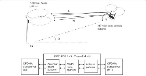
The simulation approach for the 2 × 2 spatial multiplexing MIMO was designed so that a reliable comparison between the antenna and beam domain approaches is possible. The scenario is depicted in Figure 4. The MT azimuth direction
Ωwith respect to the BS antenna array normal and the azi-muth orientationΨof the MT antenna array can be varied. The simulation model is exactly the same for the reference antenna domain case and the Butler beam case except that these two schemes apply different BS antenna/beam pat-terns of Figure 3. All the patpat-terns are calibrated to give an equal total radiated power.
In the current wideband OFDMA transceiver model, the 5 MHz bandwidth is covered by 512 frequency subcarriers, 360 of which are dedicated to data and 60 are applied as pilot subcarriers. These parameters are similar as in Worldwide Interoperability for Microwave Access (WiMAX) stand-ard [28]. In one OFDMA symbol, the data subcarriers are configured to 24 RBs in a frequency domain each of which includes 15 subcarriers. Thus a maximum of 24 dif-ferent users can be allocated to a single OFDMA symbol. In modern wireless communication networks, a large num-ber of active users may be connected simultaneously to a BS. However, at each time of radio resource allocation, only those users are assigned one or more RBs which experience favorable radio channel conditions. This brings frequency and time domain opportunism and multiuser gain to the overall system performance. The corresponding gain de-pends in practice on the efficiency of data packet scheduling algorithms in the BS Medium Access Layer. Opportunism can be deployed most efficiently in microcell type of radio environments which offer a high degree of both time- and frequency-selective fading. The specific 2 × 2 MIMO scheme under study provides an additional domain of opportunism, namely opportunistic orthogonal beam domain which offers in favorable radio channel fading instants two strong RX signals (large Eigenvalues of the beam domain MIMO chan-nel matrix). Moreover, the degree of correlation between these two beam domain signals is reduced compared to reference case of two antenna domain signals.
the 24 resource blocks, i.e., ideal channel state feedback info is assumed. In addition to BER, the correlation value be-tween the two MIMO channels and the mean Eigenvalue of the 10 best RBs are recorded on a frame by frame basis. Of course, in a fading channel, the signal level varies strongly at the receiver and there may be numerous time instants dur-ing which the received data packets are in error - even in all the 24 RBs for the specific user. This can happen also due to unfavorable BS and MT antenna orientations which cause high correlation between the two parallel MIMO channels. In the state-of-the-art systems such as the 3GPP LTE, the transmitter has channel state information about the users via a feedback process so that only favorable time instants are allocated to a specific user. If packet errors still occur, a Hybrid Automatic Repeat reQuest (HARQ) packet retrans-mission procedure is initiated. The feedback process is not in the scope of this study, and accordingly, packet retrans-mission schemes are not included in the simulation model. However, the continuous single-user simulation results can be post-processed to find out the success rate of the packet transmissions. This approach is adequate in the current study when comparing the performance of two MIMO schemes with different BS antenna/beam patterns since exactly the same simulation model and radio channel reali-zations are applied in both cases.
Table 1 summarizes the main parameters used in the simulation.
Simulation results
Spatial correlation of MIMO channels
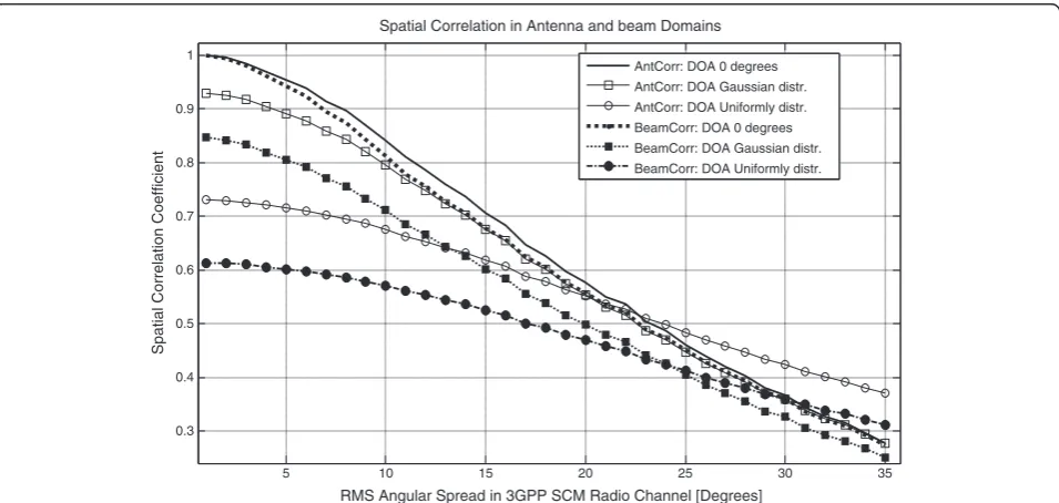
The analytical spatial correlation results in the antenna and beam domains were calculated using (8) and assuming that the beam patterns at the transmitting mobile terminal were ideally omnidirectional (antenna gain is in unity in all azimuth directions). The base station antenna and beam patterns of Figure 3 were deployed. The standard deviation of the AS of propagation paths at the BS antenna array was modeled as Laplace distributed using the approach of the SCM model implementation in [21]. The semi-analytical spatial correlation results at a BS antenna array in the an-tenna and beam domains are shown in Figure 5. The results indicate that the degree of spatial correlation in the orthog-onal beam domain is smaller than in the antenna domain. The difference is rather small for the case in which the mobile terminal is located in the direction of the antenna array normal (direction of arrival, DOA, equals 0°). If the DOA is Gaussian distributed within a 120° sector, the de-gree of correlation between beams is significantly smaller than that between antennas. This difference is even more pronounced if the DOA is uniformly distributed over 360° in azimuth. Figure 5 shows also that the benefit of the beam domain approach is larger when the angular spread is smaller. For typical angular spread values of 2° to 15° [24], the beam domain approach appears to perform espe-cially well.
Table 1 Simulation parameters
Parameter Value
MIMO mode 2 × 2 spatial multiplexing
MIMO receiver algorithm LMMSE
Carrier frequency 2 GHz
Bandwidth 5 MHz
Multiple access scheme OFDMA
Frame length 24 OFDMA symbols
OFDMA symbol duration 102.8μs
Frame duration 3.1 ms
Modulation 64 QAM
Coding Convolutional turbo coding, rate 1/2
Number of OFDMA subcarriers 512
Number of data subcarriers 360
Number of pilot subcarriers 60
Resource blocks per OFDMA symbol 24
Data subcarriers per RB 15
RB size 24 × 15 subcarriers
Cyclic prefix length 1/32 of OFDMA symbol length
Pilot boosting for MIMO 5.8 dB
Channel estimation scheme Least squares
Mobile velocity 33.3 m/s
5 10 15 20 25 30 35
0.3 0.4 0.5 0.6 0.7 0.8 0.9 1
Spatial Correlation in Antenna and beam Domains
RMS Angular Spread in 3GPP SCM Radio Channel [Degrees]
Spatial Correlation Coefficient
AntCorr: DOA 0 degrees AntCorr: DOA Gaussian distr. AntCorr: DOA Uniformly distr. BeamCorr: DOA 0 degrees BeamCorr: DOA Gaussian distr. BeamCorr: DOA Uniformly distr.
In order to compare the semi-analytical spatial correlation results in the antenna and beam domains (Figure 5) with simulation results, the SCM channel model was applied to generate sequences of 2 × 2 MIMO channel impulse responses. In the simulation model, we calculate the correlation coefficient between the two parallel data streams for each transmission time slot using the same approach as in [27]:
ρ¼E h1 h2
; ð9Þ
in whichEdenotes expectation, * refers to complex con-jugation, and h1 and h2 correspond to the wideband
(multi-tap) radio channel of data stream 1 from the TX antenna 1 to each of the two RX antennas. Here we select only the best sub-band out of the 24 possible ones that gives fewest bit errors. The channel coefficient vector h1
of the best sub-band consists of a concatenated vector of {h11h12} where each of h11and h12comprise 15 channel
coefficients in frequency domain of the applied time slot to RX antennas 1 and 2, respectively (see Figure 4). Simi-larly,h2describes the channel coefficients {h21h22} of the
same time slot for the data stream 2 from the TX antenna 2 to both RX antennas. It is noted that in simulations, we evaluate the spatial correlation of parallel MIMO channels which takes into account the spatial correlation character-istics of both the TX and RX antennas. The correlation coefficientρin (9) for each time slot of data packet trans-mission is calculated using a MATLAB™function‘corrcoef (h1,h2)’. It is noted that the 3GPP SCM model enables to
integrate the actual TX and RX antenna patterns into a radio channel simulation. Therefore, the antenna and beam domain correlation values are obtained by exactly the same simulation model. The only difference is the dif-ferent antenna and Butler beam patterns at the BS end (shown in Figure 3) which were integrated into the 3GPP SCM model. In the following, the simulation results were obtained by simulating 15,000 OFDMA radio frames in a fast fading ITU Pedestrian B environment. The azimuth direction of the mobile terminal with respect to the BS orientation was uniformly distributed over 0°…360°, and the MT orientation was random. Simulations covered 300 different MT directions with random MT orientations and each of them consisted of 50 radio frames with fast fading. MT speed was set to 120 km/h in order to provide continuously changing MIMO channel but practically non-correlated fading between consecutive radio frames (channel coherence time is 2 ms, approximately).
Figure 6 shows the simulated spatial correlation between the two parallel data streams for the chosen RB in the refer-ence antenna domain and in the Butler beam domain. Plots illustrate the cumulative distribution functions (CDF) of the spatial correlation coefficients in the antenna and beam domains. Since the correlation calculation is performed for
the RB with the lowest BER (i.e., post-detection BER esti-mation), the receiver SNR was set to a high level of 26 dB in order to minimize the impact of noise on the RB selec-tion. The SNR level of 26 dB reflects the performance for a mobile terminal close to the BS which enables efficient usage of the 64-QAM modulation [17]. The plots indicate clearly that the beam domain approach provides constantly a lower degree of spatial correlation. As an example, the probability of achieving lower than 0.8 correlation is about 20% in the beam domain but less than 13% in the antenna domain. The result is well in line with the one from the semi-analytical calculations (Figure 5).
The above study of simulated spatial correlation proper-ties takes into account opportunism both in the space/ beam, time, and frequency domains due to the fact that the best sub-band in BER sense is selected and also the best time instants (radio frames) can be deployed. This approach does not only reflect the pure spatial correlation between beams/antennas but also guarantees that the Eigenvalues of the MIMO channel matrix are adequate for the required BER performance. This type of opportunistic fixed beam MIMO is feasible due to the fact that in a frequency-selective fading, the Eigenvalues of the beam domain MIMO channel matrix vary constantly in both the frequency and time domains. In practice, the deployment of this scheme requires adaptive radio link techniques in which the receiver is reporting to the transmitter the favorable time instants as well as the best resource blocks in the frequency domain. State-of-the-art technologies such as the 3GPP LTE facilitate this type of feedback [16,17].
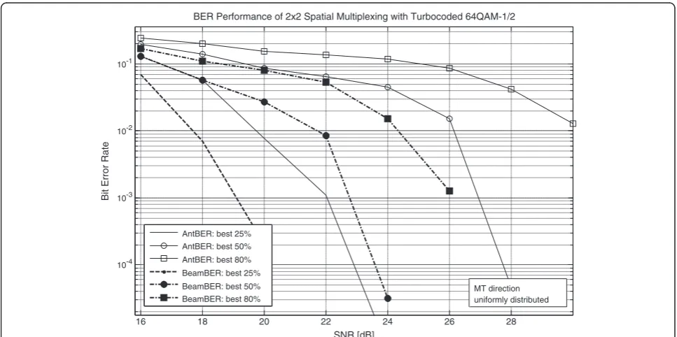
Coded bit-error-rate and MIMO channel throughput
Monte Carlo simulations assess also the link level perform-ance of spatial multiplexing in terms of turbo-coded BER and data throughput. Figure 7 illustrates the BER plots for the ITU Pedestrian B radio channel. The beam domain MIMO outperforms the antenna domain MIMO by about 6 dB at BER level of 10−2if the best 80% of the radio frames are taken into account. If the MIMO scheme selects adap-tively only the best 50% or 25% of the radio frames for spatial multiplexing, the gain in favor of fixed beam MIMO is roughly 4 dB and 2.8 dB, respectively, at BER level of 10−3. The BER performance corresponds well to the above findings that the MIMO channel correlation is lower in the fixed beam case. However, it is obvious that the lower de-gree of correlation between the MIMO channels in the fixed beam case is not the only factor for better BER per-formance. The opportunistic beam-frequency-time domain radio resource allocation is able to take benefit of those radio RBs which have not only a low degree of correlation between the MIMO channels but also an adequate power level in both MIMO channels.
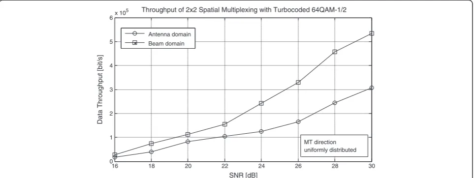
data that was employed for Figure 7. Accordingly, the throughput was evaluated using 15,000 radio frames which were transmitted through the ITU Pedestrian B radio chan-nel. The calculation is based only on the best RB of each radio frame in a way that only an error-free frame is taken
into account. Therefore, the deployed bandwidth for the data is only about 200 kHz (5 MHz/24, see Table 1) which explains the relatively low data rates in Figure 8. The throughput gain of the fixed beam 2 × 2 MIMO scheme is approximately 38% at SNR level of 20 dB and 100% at 26
0.3 0.4 0.5 0.6 0.7 0.8 0.9 1
0 0.1 0.2 0.3 0.4 0.5 0.6 0.7 0.8 0.9
Degree of Correlation
Probability
Empirical CDF of MIMO channel correlation in Simulated ITU Pedestrian B Radio Channel
Antenna domain Beam domain
Figure 6Simulated mean spatial correlation of the chosen RB.Mean spatial correlation of the chosen RB for the fixed beam approach (BeamCorr) and the reference antenna approach (AntCorr) as a function of the SNR in ITU Pedestrian B radio channel environment. Simulation covered 300 MT orientations with 50 radio frames in each of them.
16 18 20 22 24 26 28
10-4 10-3 10-2 10-1
BER Performance of 2x2 Spatial Multiplexing with Turbocoded 64QAM-1/2
SNR [dB]
Bit Error Rate
AntBER: best 25% AntBER: best 50% AntBER: best 80% BeamBER: best 25% BeamBER: best 50% BeamBER: best 80%
MT direction uniformly distributed
dB SNR. The spectral efficiency of the reference antenna domain case for the deployed RB bandwidth is 0.4 bit/s/Hz and 0.8 bit/s/Hz at 20 dB and 26 dB SNR levels, respect-ively. For the fixed beam case, the corresponding values are 0.54 bit/s/Hz and 1.6 bit/s/Hz. The relatively low spectral efficiency values are due to the fact that the simulated MT direction is uniformly distributed and the MT antenna orientation is random. Thus, there are a number of ill-fated MT directions and orientations where the MIMO transmissions are roughly parallel to either BS or MT an-tenna array directions leading to high correlation of MIMO channels.
Finally, Figure 9 shows the MIMO link performance in antenna and beam domains when the MT azimuth direc-tion Ω scans a 120° sector by 1° steps, and MT azimuth orientation Ψ is fixed to 0° (see Figure 4). The top plot shows average correlation between the two MIMO chan-nels, and the bottom plot shows average Eigenvalues of the MIMO channel matrices. The SNR level was set to 24 dB in order to guarantee the operation at a sufficiently good signal level. Thus, reliable calculations of correlation coeffi-cients and Eigenvalues are possible since they are based on the estimated MIMO channels at the receiver. This approach was selected since it takes into account the im-portant impact of channel estimation to the performance comparison. In simulations, each of the 121 angular posi-tions consists of a continuous sequence of 40 radio frames from each of which 10 RBs with lowest BER are used for calculating the correlation and Eigenvalue averages. Thus the averages are determined over favorable frequency sub-bands which cover roughly 42% (5/12) of the total band-width. Ten best sub-bands were selected due to the fact that they are obvious candidates for data packet allocation.
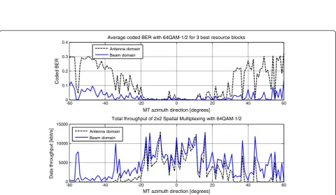
The results show that in beam domain, the correlation values are consistently smaller than those in antenna domain and that the difference gets larger the more the mobile terminal direction deviates from the BS antenna array normal. This corresponds well with the semi-analytical result of Figure 5. Moreover, the average Eigenvalues of MIMO channel matrices are clearly larger in beam domain. Both these results contribute to better BER and data throughput performance in the beam domain as indicated by Figures 7 and 8. It is also noted that the difference in MIMO channel correlation is larger when the angular deviation is larger from MT azimuth direction of 0°, in which the BS and MT antenna arrays are parallel. This result is in a good agreement with the semi-analytical results of Figure 5. The difference in Eigenvalues follows the same pattern. This phenomenon can be explained by the fact that increasing deviation from the MT azimuth direction of 0° (i.e., from BS antenna array normal, 90° in Figures 2 and 3) increases the beam gain of the other MIMO branch while the other weaker branch can take advantage of frequency selectivity in an opportunistic manner. It is noted that gain from the opportunistic utilization of frequency selectivity can be larger than the decrease in beam gain. Figure 10 illustrates the coded BER and link throughput in the same simulation scenario as that of Figure 9. The coded BER for each dir-ection is averaged over the best three RBs in all 40 con-tinuous radio frames while the throughput is calculated as a frame average of the payload bits of all successfully received RBs taking into account the frame duration. Again, the performance gain in the beam domain is larger when the MT azimuth deviation is larger from 0°. In the beam domain, we get 24,452 successful RBs out of 48,400 possible ones while the corresponding figure in the
16 18 20 22 24 26 28 30
0 1 2 3 4 5 6x 10
5 Throughput of 2x2 Spatial Multiplexing with Turbocoded 64QAM-1/2
SNR [dB]
Data Throughput [bit/s]
Antenna domain Beam domain
MT direction uniformly distributed
-60 -40 -20 0 20 40 60 0.7
0.8 0.9 1
Average correlation between MIMO channels for 10 best resource blocks
Correlation coefficient
MT azimuth direction [degrees]
-60 -40 -20 0 20 40 60
0.4 0.6 0.8 1 1.2 1.4
Average Eigenvalues of 2x2 MIMO channel matrices for 10 best resource blocks
Eigenvalue magnitude
MT azimuth direction [degrees]
Antenna domain Beam domain
Antenna domain Beam domain
Figure 9Simulated average spatial correlation and Eigenvalues.Average spatial correlation between the two MIMO channels (top) and average Eigenvalues of the 2 × 2 MIMO channel matrices (bottom) as a function of MT azimuth direction inside a 120° sector. Averaging was performed over the frequency sub-bands covering ten RBs with lowest BER. The simulation consisted of 121 angular MT positions with 40 radio frames in each of them. It was carried out with fixed SNR of 24 dB in ITU Pedestrian B radio channel environment. Spatial multiplexing in beam domain benefits from lower MIMO channel correlation and larger Eigenvalues of the MIMO channel matrix.
-60 -40 -20 0 20 40 60 0
0.1 0.2 0.3 0.4
Average coded BER with 64QAM-1/2 for 3 best resource blocks
Coded BER
MT azimuth direction [degrees]
-60 -40 -20 0 20 40 60 0
5000 10000 15000
Total throughput of 2x2 Spatial Multiplexing with 64QAM-1/2
Data throughput [kbit/s]
MT azimuth direction [degrees]
Antenna domain Beam domain
Antenna domain Beam domain
antenna domain is 13,523. The gain in total data throughput is roughly 80%. The average data rate over 40 continuous radio frames is up to 13 Mbit/s in best azimuth positions of the MT.
Conclusions
An opportunistic fixed-beam OFDMA MIMO concept was studied in a 2 × 2 spatial multiplexing case. The novel concept allows a straightforward implementation into practical wireless systems with no need to modify the system specifications. Simulations indicated that the beam domain MIMO scheme outperformed clearly the corresponding antenna domain OFDMA approach in a well-established 3GPP SCM microcell radio channel scenario. The performance gain is based on the fact that beamforming increases the opportunities for favor-able space-time-frequency slots in a wideband radio channel. In adaptive multiuser OFDMA systems like the 4G LTE, these slots can be deployed opportunistically by deploying advanced radio resource management, e.g., in a form of efficient data packet scheduling. In the beam domain, the allocated slots show on average lower MIMO channel correlation and larger Eigenvalues of the MIMO channel matrices. These two facts result in significantly better radio link BER performance in the beam domain compared to that in the antenna domain. Accordingly, the gain in system data throughput can be as high as 80%.
In future research, the performance of the proposed fixed beam scheme is studied at a mobile station receiver, for example assuming vehicle rooftop antennas. The scheme may also suit to the prospected 5G technologies which apply large 2-dimensional beamforming antenna arrays (even of size 32 × 32 antenna elements). The fixed beam approach enables simple and practical algorithms even with large 2D antenna arrays when adaptively deploying diversity, conventional beamforming, and spatial multiplexing.
Abbreviations
3GPP:3rd Generation Partnership Project; 4G: 4th generation; 5G: 5th generation; AS: angular spread; BER: bit-error-rate; BM: Butler matrix; BS: base station; CQI: channel quality indicators; DOA: direction of arrival;
HARQ: Hybrid Automatic Repeat reQuest; HSDPA: high-speed downlink packet access; LTE: long term evolution; MIMO: multiple input multiple output; MMSE: minimum mean square error; MT: mobile terminal; OFDMA: orthogonal frequency domain multiple access; PAS: power azimuth spread; PMI: precoding matrix indicators; QAM: quadrature amplitude modulation; RB: resource block; RF: radio frequency; RI: rank indicators; RMS: root mean square; RX: receiver; SCM: spatial channel model; SM: spatial multiplexing; SNR: signal to noise ratio; TX: transmitter; ULA: uniform linear array; UMTS: Universal Mobile Telecommunications System.
Competing interests
The author declares no competing interests.
Acknowledgements
The author thanks Mr. Tuomo Haarakangas and Dr. Taavi Hirvonen of Elektrobit Wireless Communications Ltd. for performing the RF simulations of the antenna patterns and for valuable discussions. Tekes (Finnish Funding Agency for Technology and Innovation) is acknowledged for financial support.
Received: 23 June 2014 Accepted: 19 October 2014 Published: 4 November 2014
References
1. GJ Foschini, Layered space-time architecture for wireless communication in a fading environment when using multi-element antennas. Bell Labs. Tech. J.1(2), 41–59 (1996)
2. SM Alamouti, A simple transmit diversity technique for wireless communications. IEEE J. Selected Areas Commun.16, 1451–1458 (1998) 3. E Telatar, Capacity of multi-antenna Gaussian channels. Eur. Trans. Telecommun.
10(6), 585–595 (1999)
4. GJ Foschini, MJ Gans, On limits of wireless communications in a fading environment when using multiple antennas. Wireless Personal Commun. 6, 311–335 (1998)
5. V Tarokh, H Jafarkhani, AR Calderbank, Space-time block code from orthogonal designs. IEEE Trans. Inf. Theory45, 1456–1467 (1999) 6. R Heath Jr, A Paulraj, Switching between multiplexing and diversity based
on constellation distance. IEEE Trans. Commun.53(6), 962–968 (2005) 7. IST-2003-507581 WINNER Deliverable D2.7 v.1.0, Assessment of Advanced
Beamforming and MIMO Technologies, http://www.ist-winner.org/ DeliverableDocuments/D2.7v1.1.pdf. Accessed 16 Sep 2014 8. A Goldsmith, SA Jafar, N Jindal, S Vishwanath, Capacity limits of MIMO
channels. IEEE J. Selected Areas Commun.21(5), 684–702 (2003) 9. SA Jafar, AJ Goldsmith, Multiple-Antenna capacity in correlated Rayleigh
fading with channel covariance information. IEEE Trans. Wireless Commun. 4, 990–997 (2005)
10. 3GPP TR 25.996 V6.1.0 (2003–09). Technical Report, http://www.3gpp.org/. Accessed 16 Sep 2014
11. I Kim, K Lee, J Chun, A MIMO antenna structure that combines transmit beamforming and spatial multiplexing. IEEE Trans. Wireless Commun. 6(3), 775–779 (2007)
12. H Holma, A Toskala (eds.),WCDMA for UMTS: HSPA Evolution and LTE (John Wiley & Sons, Chichester, 2007)
13. A Papadogiannis, A Burr, Multi-Beam Assisted MIMO - a Novel Approach to Fixed Beamforming, inFuture Network and Mobile Summit 2011 Conference Proceedings, ed. by P Cunningham, M Cunningham (IIMC International Information Management Corporation). http://ieeexplore.ieee.org/xpl/login. jsp?tp=&arnumber=6095241&url=http%3A%2F%2Fieeexplore.ieee.org% 2Fxpls%2Fabs_all.jsp%3Farnumber%3D6095241. Accessed 16 Sep 2014 14. M Litzenburger, M Ohm, H Hu,Multi User MIMO with Fixed Beamforming for
FDD Systems, IEEE 802.16 Broadband Wireless Access Working Group, 2007. http://www.wirelessman.org/tgm/contrib/S80216m-07_168.pdf. Accessed 16 Sep 2014
15. P Viswanath, DNC Tse, R Laroia, Opportunistic beamforming using dumb antennas. IEEE Trans. Inf. Theory48(6), 1277–1294 (2002)
16. H Holma, A Toskala (eds.),LTE for UMTS: OFDMA and SC-FDMA Based Radio Access(John Wiley & Sons, Chichester, 2009)
17. S Sesia, I Toufik, M Baker (eds.),LTE, The UMTS Long Term Evolution(John Wiley & Sons, Chichester, 2011)
18. J Winters, Optimum combining in digital mobile radio with cochannel interference. IEEE J. Select Areas Commun.2(4), 528–539 (1984) 19. CST Microwave Studio®. http://www.cst.com/Content/Products/MWS/
Overview.aspx. Accessed 16 Sep 2014
20. M Döttling, W Mohr, A Osseiran (eds.),Radio Technologies and Concepts for IMT-Advanced(John Wiley & Sons, Chichester, 2009)
21. J Salo, G Del Galdo, J Salmi, P Kyösti, M Milojevic, D Laselva, C Schneider,MATLAB implementation of the 3GPP Spatial Channel Model (3GPP TR 25.996), 2005. http:// radio.aalto.fi/en/research/rf_applications_in_mobile_communications/ propagation_research/matlab_scm_implementation/. Accessed 16 Sep 2014 22. JP Kermoal, L Schumacher, KI Pedersen, PE Mogensen, F Frederiksen, A
stochastic MIMO radio channel model with experimental validation. IEEE J. Selected Areas Commun.20(6), 1211–1226 (2002)
23. MA Jensen, Y Shi, Y Yang, Channel Covariance Modeling for Multi-User MIMO Systems, in2010 Proc Fourth European Conference on Antennas and Propagation (EuCAP), 2010, pp. 1–5
24. KI Pedersen, PE Mogensen, BH Fleury, A stochastic model of the temporal and azimuthal dispersion seen at the base station in outdoor propagation environments. IEEE Trans. Vehicular Techn.49(2), 437–447 (2000)
26. Motorola,Correlated System Level Spatial Channel Model, 3GPP/3GPP2 Joint Spatial Channel Modeling Adhoc Meeting, 2002. (ftp://ftp.3gpp2.org/TSGC/Working/2002/ 3GPP_3GPP2_SCM_(Spatial_Modeling)/ConfCall-1-20020503/SCM-020% 20Correlated%20Spatial%20Channel%20Model.pdf. Accessed 16 Sep 2013 27. CB Ribeiro, A Richter, V Koivunen, Stochastic Maximum Likelihood
Estimation of Angle- and Delay-Domain Propagation Parameters, inIEEE Int’l Symp. Personal, vol. 1 (Indoor and Mobile Radio Communications, Berlin, Germany, 2005), pp. 624–628
28. L Nuaymi,WiMAX, Technology for Broadband Wireless Access(John Wiley & Sons, Chichester, 2007)
doi:10.1186/1687-1499-2014-183
Cite this article as:Ylitalo:Performance of opportunistic fixed-beam spatial multiplexing in OFDMA uplink.EURASIP Journal on Wireless Communications and Networking20142014:183.
Submit your manuscript to a
journal and benefi t from:
7 Convenient online submission 7 Rigorous peer review
7 Immediate publication on acceptance 7 Open access: articles freely available online 7 High visibility within the fi eld
7 Retaining the copyright to your article