ISSN (Print) : 2320 – 3765 ISSN (Online): 2278 – 8875
I
nternational
J
ournal of
A
dvanced
R
esearch in
E
lectrical,
E
lectronics and
I
nstrumentation
E
ngineering
(An ISO 3297: 2007 Certified Organization)
Website: www.ijareeie.com
Vol. 6, Issue 2, February 2017
Wireless Temperature Monitoring System
Using Microcontroller
1
B.Sanjai Prasad, 2V.Shiva Naga Malleswara Rao ,3R.Sriram Pranav, 4 K.Manoj, 5M.Shashidhar
1
Associate Professor, Dept. of ECE, Lords Institute of Engineering & Technology, Hyderabad, Telangana, India
2,3,4,5
U.G Students, Dept. of ECE, Lords Institute of Engineering & Technology, Hyderabad, Telangana, India
ABSTRACT:To get rid of the problem of Obscurity to control temperature in industries, a microcontroller based controller has been proposed. A temperature sensor has been used to measure the temperature of the room and the speed of the fan is varied according to the room temperature using pulse width modulation technique.We have used AT89C51 microcontroller kit for interfacing our system. This paper is about controlling various DC fan speed devices using PWM which is working on Radio frequency.Let us take example if we can connect the DC fan at the output then we canswitch on or off of fan at a desiredspeed using the PWM technique and the status of various devices is displayed on LCD.In this paper we are using RF transmission because with the help of IR transmitter there is a problem of directivity and range of working, that problem is eliminated with RF transmission. RF has better directivity and frequency range.
KEYWORDS: Microcontroller, LCD, Reception, Transmission, Wireless
I. INTRODUCTION
The goal of the paper is to achieve intelligent devicecontrol and secure environmental working conditions byinterfacing various sensors and devices to the AT89C51 microcontroller and RF modules withthe Atmel controller for data transmission respectively.Wireless based industrial automation is a prime concernin our day-to-day life. Industrial automations depend onthe power systems and which requires distance controland regulated systems. Wireless Control Networks(WCNs) have revolutionized the design of emergingembedded systems and triggered a new set of potentialapplications. In addition to building automation,environmental surveillance, or military operationsIndustrial automation is also expected to greatly benefitfrom WSNs in terms of faster installation andmaintenance, cost savings, and easier plantreconfiguration. RF is an emerging short-range, lowrate wireless network technology. RF also presentssome potentially interesting features for supportinglarge-scale ubiquitous computing applications, namelypower-efficiency, timeliness and scalability.In managing the move to wireless, it is clear thatcommon wireless protocols such as Wi-Fi and Bluetoothcan be utilized on the factory floor.The challenge is to understand how to utilize wirelesssolutions, developed for IT applications, as replacementsfor wired systems in time-critical scenarios typical offactory floor domains. To date, most wireless systems inproduction systems are focused on applications thatrequire polling frequencies on the order of seconds orlonger. Standardization of technology again plays animportant role for globalization of these profiledevelopments.
II. RELATED WORK
ISSN (Print) : 2320 – 3765 ISSN (Online): 2278 – 8875
I
nternational
J
ournal of
A
dvanced
R
esearch in
E
lectrical,
E
lectronics and
I
nstrumentation
E
ngineering
(An ISO 3297: 2007 Certified Organization)
Website: www.ijareeie.com
Vol. 6, Issue 2, February 2017
III. SYSTEM ARCHITECTURE
This block diagram contains the wireless transmitter section. This section has microcontroller as atransmitter module, temperature sensor LM 35, ADC 0809.Each and every module in the transmitter sectionwill be controlled by the Microcontroller. The Temperature sensor LM35 senses the temperature as analogsignal, by the use of ADC 0809 these analog signals will be converted to digital and it will be transfer to themicrocontroller. Microcontroller processes that digital signal and then transmits the digital signal through theWireless Transmitter module as an analog signal [6].ADC-809 has an inbuilt 8-channel multiplexer. It performs simultaneously A/D conversion of more thanone analog signal. When the unknown analog input equals the reference voltage, the internal comparator outputallows the digital output to become available at the output of the 8-bit latch. The characteristics of referencevoltage is as shown in graph no.1 While the process of A/D conversion is initiated by positive pulse at theterminal marked “START OF
CONVERSION” the A/D converter produces the pulse at the terminal marked “END OF THE CONVERSION”. This
pulse is used to inform microcontroller that the cycle of A/D conversionhas been completed.
Figure 1: Block diagrams of proposed system
ISSN (Print) : 2320 – 3765 ISSN (Online): 2278 – 8875
I
nternational
J
ournal of
A
dvanced
R
esearch in
E
lectrical,
E
lectronics and
I
nstrumentation
E
ngineering
(An ISO 3297: 2007 Certified Organization)
Website: www.ijareeie.com
Vol. 6, Issue 2, February 2017
AT89C51 is a powerful microcomputer which provides a highly-flexible and cost-effective solution to many embedded control applications.
LM35:LM35 is a device which converts the physical signal into electrical signal. That’s why this is known asthe transducer. It is calibrated with the environmental temperature and it is linearly varies with thetemperature and its output is in volt. There is no need of external calibration to provide the accuracy ofthe LM35 at room temperature which is about ±¼°C. Minimum temperature that can be measured by theLM35 device is -55°C. And maximum temperature that can be measured by LM35 is 150°C. Calibrationof LM35 is done by trimming at the water level. To make the interfacing of control circuitry and readoutcircuitry very easy, low impedance at output side, output which is linear and precise inherent calibrationof LM35 plays an important role. Temperature sensor takes a very low current of order 60 μA from theinput supply. Heat loss in the LM35 is very less degree of around 0.1°C. LM35 can work in the range of-50°C to +150° which is the rated value. Another device which is also a temperature sensor of the familyof LM35 known as LM35C which ranges from -40°C to +110°C. LM35 costs around 10 rupees in Indiaand is easily available in the market which anyone can buy at any convenience store or electronics store.
RF Transmitter/ receiver (RX-434) modules: The RF receiver(RX-434) module can receive the signal transmitted by
thetransmitter from a distance up-to 1 to 1.5km. The range canbe increased up to 30 meters using a good antenna.Dout
pin of RX-434 RF Module is connected to Din pinof Decoder IC HT12D (IC 4). Din pin of IC4 receiveraddress and
data bits serially from the RF Module. DecoderIC4 separate data and address from the receivedinformation. It accepts data only if the received addressmatches with address assigned to Encoder IC1 (HT12E). Wehave used ‘1111’ as the permanent address forcommunication. Pins 1 through 8 of IC4 are address pinsand therefore 256 possible addresses are available. Theaddress on the Encoder and Decoder ICs must match for thedata to be valid.
The HT12D decoder receives serial address and datafrom the Encoder continuously with its local addresses. Ifno error or unmatched codes are found, the input data codesare decoded and transferred to the output pins. VT pin (validtransmission) goes high to indicate a valid transmission. TheHT12D provides four latch type data pins whose dataremains unchanged until new data is received.
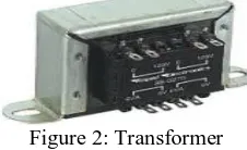
Transformer:It covert alternating current from one value to other valueof voltage with a limited loss of power. Step-uptransformers have more winding towards the secondarysection compared to primary section. This inturn increasesthe value of voltage. Step-down transformers have lesswinding towards the secondary section compared to thatwith the primary section. This inturn decreases the valueof voltage.The step down transformer is used commonly in powersupplies to reduce the high risk associated with highvoltage to considerably low voltage. The transformer hastwo coils namely primary coil and secondary coil. Betweenthese two coils there is no electrical connection rather theyare connected by the alternating magnetic field. This fieldis created by using soft-iron core of the transformer.
Figure 2: Transformer
Bridge rectifier: An electric device which periodically reverses the directionthat is from alternating current to direct current isrectifier. The output voltage from transformer is given asinput to bridge rectifier. That converts alternating currentinto direct current which is pulsating.
ISSN (Print) : 2320 – 3765 ISSN (Online): 2278 – 8875
I
nternational
J
ournal of
A
dvanced
R
esearch in
E
lectrical,
E
lectronics and
I
nstrumentation
E
ngineering
(An ISO 3297: 2007 Certified Organization)
Website: www.ijareeie.com
Vol. 6, Issue 2, February 2017
Filter:Capacitive filter is used in this project. It removes theripples from the output of rectifier and smoothens the D.C.Output received from this filter is constant until themains voltage and load is maintained constant. However,if either of the two is varied, D.C. voltage received at thispoint changes. Therefore a regulator is applied at theoutput stage.
Figure 4: Filter 1. Keil software for Microcontroller programming.
2. Flash magic software for Microcontroller burning. 3. Diptrace Software for PCB Layout.
4. Language: Embedded C Assembly.
IV. RESULTS AND DISCUSSION
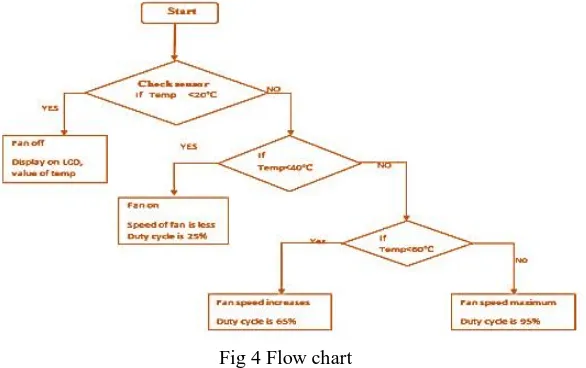
The logical representation of the software code has been presented in the flowchart form. Figure 4 shows the flowchartof the logic implemented in the modeled system.
Fig 4 Flow chart
The temperature is read from the temperature sensor and the condition is checked and the following processes are done:
1) When temperature is greater than zero and less than 20 degree Celsius, the fan is OFF.
2) When temperature is greater than 20 and less than 40 degree Celsius, the fan speed is SLOW.
3) When temperature is greater than 40 and less than 60 degree Celsius, the fan speed is MEDIUM.
4) When temperature is greater than 60, the fan speed is FAST
V. CONCLUSION& FUTURE SCOPE
ISSN (Print) : 2320 – 3765 ISSN (Online): 2278 – 8875
I
nternational
J
ournal of
A
dvanced
R
esearch in
E
lectrical,
E
lectronics and
I
nstrumentation
E
ngineering
(An ISO 3297: 2007 Certified Organization)
Website: www.ijareeie.com
Vol. 6, Issue 2, February 2017
for regulatingthe speed manually. Various graphs were plotted to show the various relationships between different parameters.PWM technique is discovered to be suitable for controlling fan speed in keeping with room temperature. After evaluating duty cycle and speed of DC Fan in line with temperature variation. In this design, the RF provide low power consumption, low cost and easyRF communication to permit remote control andpresent day size of business retailers which will shopstrength. RF era is suitable for the utilityin strength monitoring device. It can provide reliablesecurity for the operation of electrical energy structures.The machine is small, simple, and cost effective and desirable forRF control of device.
REFERENCES
[1]. Muhammad A Mazidi, Janice Mazidi, RolimMc Kinaly, The 8051 [2]. George Kennedy, Electronics Communication ,Tata Mc Graw Hill
[3]. Bernard Skalar, pabitra Kumar Ray, DigitalCommunication, Second Edition, PearsonEducation. [4]. G.K. Dubey, S.R. Doradla, A.Joshi, R.M.K.Sinha, Power Electronics, New Age.
[5]. Digital and analog communication by B.P. Lathi.Zhi Ding(international 4th Edition), oxforduniversity press. [6] I. John, PIC Microcontroller Project Book, second ed., Mc Graw-Hill, Singapore, 2000.
[7] Xiaodong Xia, Based on Single Chip Microcomputer Remote Wireless Control System Design. Coal Mine Machinery, vol. 32 (8), pp. 202-204, 2011.
[8] J. Vig and A. Ballato, “Ultrasonic Instruments and Devices”, Academic Press Inc. pp. 637– 701 (Chapter7: Frequency Control Devices). 1999 [9] P. Spasov, “Micro controller Technology, The 68HC1 l”, Prentice Hall, 1992.
[10] M. H. Rashid, Power Electronics Circuits, Devices and Applications, third ed., Prentice Hall, United States of America, 2004.
[11] Song jian, Jiang junsheng, Zhao wenliang. "The DC-motor PWM Speed Regular system Base on single-chip Microcomputer". Study onAgricultural Mechanization, 1(1):102-103, 2006.
[12] J. Holtz, “Pulse width modulation: a survey,” IEEE Trans. Industrial Electronics, vol. IE-39, no.5 pp.410-420, 1992.
[13] S.D. Barman, A. Hussain, T. Ahmed, Speed Control of DC Motor Using PWM Technique: Pulse Width Modulated DC Motor Control, LAPLambert Academic Publishing, 2012.
[14] T.Pialis and K. Phang, “Analysis of timing Jitter in Ring Oscillators Due to Power Supply Noise”, Circuits and Systems, ISCAS’03,Proceedings of the 2003 International Symposium. 2003.
[15] Vaibhav Bhatia and Gavish Bhatia “Room Temperature based Fan Speed Control System using Pulse Width Modulation Technique”International Journal of Computer Applications (0975 – 8887) Volume 81 – No5, November 2013
BIOGRAPHY
B.Sanjai Prasad is working as Associate. Professor, in the Department of Electronics & Communications, Lords Institute of Engineering and Technology, Hyderabad, Telangana, India. He has received M.E from O.U campus Hyderabad, India. He is Pursuing Ph.D from IIT(ISM), Dhanbad, India. His research interested in Wireless Sensor Networks. He had 12 years of teaching experience.
V.Shiva Nagamalleswara Rao, Pursuing B.TECH 3rd year in Lords Institute of Engineering and Technology in the Dept.of ECE.
ISSN (Print) : 2320 – 3765 ISSN (Online): 2278 – 8875
I
nternational
J
ournal of
A
dvanced
R
esearch in
E
lectrical,
E
lectronics and
I
nstrumentation
E
ngineering
(An ISO 3297: 2007 Certified Organization)
Website: www.ijareeie.com
Vol. 6, Issue 2, February 2017
R.Sriram Pranav,Pursuing B.TECH 3rd year in Lords Institute of Engineering and Technology in the Dept.of ECE.