Automation of Sewage Treatment Plant Using
PLC & SCADA
Rachana R. Sangitrao
Assistant Professor, Dept. of Instrumentation & Control, D. Y. Patil Engineering College, Akurdi, Pune, India
ABSTRACT: The term, Industrial Automation generally refers to the science and technology of process control of various plants such as chemical and petrochemical plants, oil refineries, iron and steel plants, power plants, paper pulp and paper mills, pharmaceutical, food and beverage industries, water and waste water treatment plants, oil and gas fields, etc.
Plant Automation is one of the important requirements, which improves the quality of products as well as reduces requirements of manpower. Industrial automation has taken a giant step to control industrial machineries and industrial processes by replacing human operators. Now a day’s Programmable Logic Controller (PLC) and SCADA systems are extensively used in industries. Industry people are encouraging use of Programmable Logic Controller (PLC) for plant automation. The origin of PLC comes from the American Automotive Industries. With the advent of industrial automation, we will briefly discuss the Programmable Logic Controller (PLC) used in our plant.
This paper explains the work done for Automation of Sewage Treatment Plant using PLC and SCADA. In this work, we have used Schneider Electrics Controller and SCADA, Unity Pro XL and Vijeo-Designer software’s.
KEYWORDS: Programmable logic Controller, Supervisory Control and Data Acquisition, Sewage Treatment Plant.
I. INTRODUCTION
Automation: - Automation is the use of control systems and information technologies reduce the need for human work in the production of goods and services. In the scope of industrialization, automation is a step beyond mechanization. Whereas mechanization provided human operators with machinery to assist them with the muscular requirements of work, automation greatly decreases the need for human sensory and mental requirements as well. Automation plays an increasingly important role in the world economy and in daily experience. PLC and DCS are the most widely used tools.
Process Control is a statistics and engineering discipline that deals with architectures, mechanisms, and algorithms and for maintaining the output of a specific process within a desired range.
In old process controls, manual control of application was done where all the actions and decisions were done humans considering the errors, also with the help of hard wired logic.
Process control systems can be characterized as one or more of the following forms:
Discrete–Found in many manufacturing, motion and packaging applications. Robotic assembly, such as that found in automotive production, can be characterized as discrete
process control. Most discrete manufacturing involves the production of discrete pieces of product, such as metal stamping.
Batch – Some applications require that specific quantities of raw materials be combined in specific ways for particular durations to produce an intermediate or end result. Batch processes are generally used to produce a relatively low to intermediate quantity of product.
Continuous – Often, a physical system is represented through variables that are smooth and uninterrupted in time. Continuous processes in manufacturing are used to produce very large quantities of product.
A commonly used control device called a Programmable Logic Controller, or a PLC is used to read a set of digital and analog inputs, apply a set of logic statements, and generate a set of analog and digital outputs. Larger more complex systems can be controlled by a Distributed Control System (DCS) or SCADA system.
To control the industrial machineries and processes we require some automation tools. Following are some automation tools used in the industries:
1. PLC – Programmable Logic Controller 2. HMI – Human Machine Interface 3. DCS – Distributed Control System
4. SCADA – Supervisory Control and Data Acquisition 5. LIMS – Laboratory Information Management System 6. PAC – Programmable Automatic Controller
7. MES – Manufacturing Execution System
A. PROGRAMMABLE LOGIC CONTROLLER (PLC):
A Programmable Logic Controller commonly known as PLC is a digital computer used for automation of electromechanical processes, such as control of machinery on factory assembly lines, amusement rides, or lighting fixtures. PLCs are used in many industries and machines. Unlike general-purpose computers, the PLC is designed for multiple inputs and outputs arrangements, extended temperature ranges, immunity to noise, resistance to vibration and impact. The main difference from other computers is that PLC can be used in hazardous and severe conditions (dust, moisture, heat, cold, etc) and have the facility for extensive input/output (I/O). These connect the PLC to sensors and actuators.
The different manufacturers of PLC are listed below: 1. Allen-Bradley
2. Siemens 3. Mitsubishi 4. Messung 5. GE Fanuc 6. Philips 7. ABB
8. Schneider electric 9. Omron
B. HUMAN MACHINE INTERFACE (HMI):
In the industrial design field of human –machine interaction, the HMI is the space where interaction between humans and machines occurs. The goal of interaction between a human and a machine at the user interface is effective operation and control of the machine, and feedback from the machine which aids the operator in making operational decisions. Examples of this broad concept of user interfaces include the interactive aspects of computer operating systems, hand tools, heavy machinery operator controls, and process controls. The design considerations applicable when creating user interfaces are related to or involve such disciplines as ergonomics and psychology.
A user interface is the system by which people (users) interact with a machine. The user interface includes hardware (physical) and software (logical) components. User interfaces exist for various systems, and provide a means of:
Input, allowing the users to manipulate a system, and/or
Output, allowing the system to indicate the effects of the users' manipulation.
Generally, the goal of human-machine interaction engineering is to produce a user interface which makes it easy, efficient, and enjoyable to operate a machine in the way which produces the desired result. This generally means that the operator needs to provide minimal input to achieve the desired output, and also that the machine minimizes undesired outputs to the human.
The different manufacturers of HMI are listed below: 1. Cursor Controls
II. LITERATURE REVIEW
Programmable Logic Controllers (PLC) is a digital operational electronic device specially designed for working under industrial environment. The advantages of high reliability, good capacity and convenient operation make it widely used in automatic industrial control and electromechanical integration. And it is one of the backbones of industrial automation. And are dedicated systems used to control manufacturing processes that are continuous or batch-oriented, such as oil refining, petrochemicals, central station power generation, pharmaceuticals, food & beverage manufacturing, cement production, steelmaking, and papermaking. The survey and the literature are presented in this section.
In order to ensure the sewage treatment equipment operation cycle and the suction pump intermittent work and realize automatic SBMBR sewage treatment equipment intelligently, this paper selected MITSUBISHI FX2N series PLC to introduce SBMBR sewage treatment system for control system. By analysing of automatic control system targets, program design process is given. Eventually, designed automatic control system achieves automatically water stirring, water and control of anaerobic, anoxic, aerobic time. Automatic control system provides a reliable guarantee for the normal operation and effluent quality of SBMBR. The commissioning and operation practice has proved that system greatly improved the degree of automation and achieved good impact. [1]
Heavy metals Zn, Cu, Cd, Ni, Pb and Mn in the compressed sludge from Shenyang Northern Sewage Treatment Plant were removed by bioleaching. The results showed that: the treatment cycle of bioleaching was about 4d, water should be timely separated from sludge; After the treatment of bioleaching, the content of heavy metals in compressed sludge were below that of control standards for pollutants in sludge from agricultural use GB4284-1984, which indicated the sludge from the waste water treatment plant treated by bioleaching could be used as agricultural fertilizer; After the treatment of bioleaching, the existence forms of the six heavy metals were mainly restorable and oxidized state. These research results are very helpful to the dispose and reclamation of sludge from waste water treatment plant. [2]
III. MODICON ARCHITECTURE
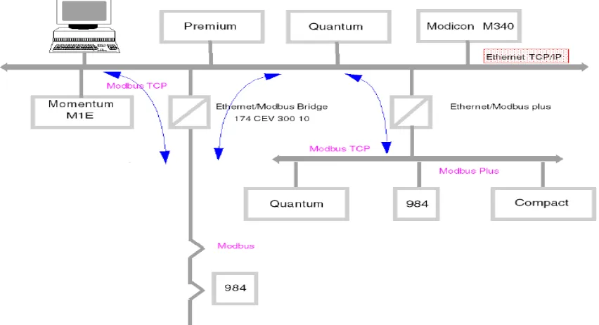
The System Architecture showed in figure is the main architecture of the Modicon PLC. In this system various PLC’s are used such as Premium, Quantum, and Modicon M340,which uses Ethernet TCP/IP, for its communication purpose, and is the PLC I have use in my project, Ethernet, Hub, Modbus Bridge, Modbus TCP, Modbus Plus along with Quantum, 984, and Compact etc.
Fig 3.2 Configuration of Modicon PLC
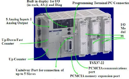
The above setup is combination of with various components. System Components:
3.1 Power Supply 3.2 Schneider controller 3.3 USB Programming Cable
3.4 Analog Input/Output 3.5 Digital Input/Output 3.6 Schneider HMI
IV. SYSTEM MODEL
A. PRINCIPLE OF OPERATION:
There are two different types of Biological processes for treating sewage. : i. Aerobic Process
1. Suspended growth process 2. Attached growth process
ii. Anaerobic Process 1. Suspended growth process 2. Attached growth process
Figure 4.1 Generalized Diagrams
B. PROCESS DESCRIPTION:
The Treatment Process is mainly based on the principle of FLUIDISED ATTACHED GROWTH PROCESS” and
consists mainly of the following components:
MEDIA, which provides surface area for the growth of microorganisms.
AIR GRID SYSTEM, which ensures:
-High oxygen transfer efficiency to meet the oxygen demand exerted by the microorganisms. -The fluidized state of the media
The system comprises of the following main units: a) FAB reactor tank - I
b) FAB reactor tank - II c) Tube Settler
AEROBIC
FAB
REACTOR
Bacteria
Waste water
containing
contaminants
Harmless End
Products
Presence of O
2Absence of O
2ANAEROBIC
FAB
REACTOR
CO
2+ H
2O + NEW BACTERIA
CH
4+ H
2O + NEW BACTERIA
Treatment stages:-
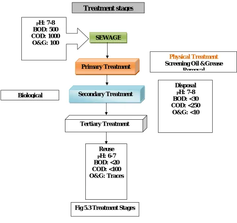
There are basically three different stages of treatment in the sewage treatment plant. • Primary Treatment
The primary treatment basically involves physical treatment like screening and oil & grease removal. • Secondary Treatment
The secondary treatment is a biological process where the major COD & BOD reduction takes place. The biological treatment provided in this plant is a Fluidised Aerobic Bioreactor which is an attached growth process. After the biological treatment there is a chlorination system also provided which helps in disinfection. Normally as per the pollution control norms the secondary treated sewage can be disposed into the drainage line without any problem.
• Tertiary Treatment
In the tertiary treatment there are filters (DMF & ACF) provided to polish the treated sewage to the extent of reuse. Here the BOD & COD levels are further brought down so that the treated water can be now reused. This tertiary treated water can be reused in various applications like Car wash, Gardening, Cooling tower, etc. This water can also be recycled if required to further treat and use in other process applications.
The treatment stages are diagrammatically represented in Fig 4.3 below.
Treatment stages
P
H: 7-8
BOD: 500
COD: 1000
O&G: 100
Primary Treatment
SEWAGE
Physical Treatment
Screening Oil &Grease
Removal
Secondary Treatment
Biological
Tertiary Treatment
Reuse
P
H: 6-7
BOD: <20
COD: <100
O&G: Traces
Disposal
P
H: 7-8
BOD: <30
COD: <250
O&G: <10
V. RESULT
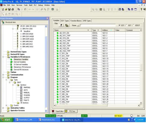
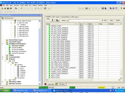
All the inputs coming from field which are digital signal in the range of 0’s and 1’s, by using Ladder Diagram Language, Structural Text language. Structured text is a textual programming language that uses statements to define what to execute. i. e. we can assign tag: = expression; (tag: = %IW0.1.0 Data); for input. And (%QW0.2.0 Data: = tag) for output.
Figure 5.1 (b): - Digital Output Mapping Using Structural Text Programming
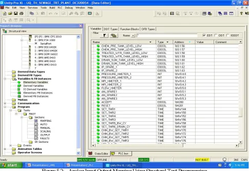
All the inputs coming from field which are digital signal in the range of 0’s and 1’s, by using Structural Text language. Structured text is a textual programming language that uses statements to define what to execute. i. e. we can assign
Figure 5.2: - Analog Input Output Mapping Using Structural Text Programming
A. (FAB-BASED) SEWAGE TREATMENT PLANT
The sewage treatment is a typical process of treating the waste which is obtained from almost all domestic complexes, Hospitals, Institutes, Malls, Offices, Industries, Schools, Marine, etc. It consists of a FAB (Fluidised Aerobic Bioreactor) which works on the principle of attached growth process which uses plastic as a media in it so that the microorganisms may grow which is the main cause in this membrane. Table 5.1 shows the temperature parameters and time of tests carried out at plant site.
Table 5.1 Sewage Treatment Process Parameter Sr.
No. Mode of operation Temperature ⁰C Time minutes
1 Filtration 120⁰C 10
2 Cooling 50⁰C 13
3 Heating 123.5⁰C 19
4 Cooling 48.5⁰C 18
Total Time in Minutes 65
1 Heating 122.5⁰C 14
2 Cooling 45.5⁰C 12
3 Heating 120⁰C 16
4 Cooling 47.5⁰C 13
Total Time in Minutes 55
Table 5.2 Deareator Tank Parameters Deareator
Sr. No. Temperature 0C Level % Pressure bar
1 55 53% 0.06 bar
2 70 65% 0.05 bar
B. CLEAN-IN-PLACE (CIP) PROCESS
In the CIP preparation, conductivity parameter is very important factor, conductivity parameter at 100Ms/cm2 for temperature 67.5 0C.
Table 5.3 CIP Preparation Process Parameters CIP Preparation
Sr. No. Conductivity Ms/cm2 Temperature 0C
1 100 Ms/cm2 67.5 0C
2 75 Ms/cm2 65 0C
3 73 Ms/cm2 64.5 0C
In the CIP supply, the flow rate of solution with conductivity and temperature is required for CIP of tanks. Example set Flow rate parameter at 10,150 LPH with temperature 64.0 C.
Table 5.4 CIP Supply Process Parameters CIP Supply
Sr. No. Flow Rate LPH Temperature 0C Conductivity Ms/cm2 1 10,150 LPH 64.5 0 C 73 Ms/cm2 2 10175 LPH 67.5 0 C 100 Ms/cm2 3 10,000 LPH 65 0C 75 Ms/cm2
When the parameters were set as per the above tables, it was observed that the plant achieved desired performance. For example in sterilization process, set temperature parameter for the heating mode at 123.5 0C to maintain this temperature for 19 minutes to sterilize the material.
VI. CONCLUSION
Hybrid Distributed Control system covers the direct automation of the Industrial process and machines, spanning the integration of sensors, controllers, and man machine interface in to control system that had handled the moment to moment demands of the process operation.
After Factory Acceptance Test, we found that the application control module is working satisfactorily and process can be operated in Auto Mode according to the control philosophy given by Alfa Laval (I) Ltd., Pune to Analogic Automation, Pune using Hybrid DCS and SCADA.
REFERENCES
[1] K. R. Chowdhury, M. Di Felice, “Search: a routing protocol for mobile cognitive radio ad hoc networks,” Computer Communication Journal, vol. 32, no. 18, pp. 1983-1997, Dec.20
[2] K. M. Passino, “Biomimicry of bacterial foraging for distributed optimization,” IEEE Control Systems Magazine, vol. 22, no. 3, pp. 52-67, 2002.
[3] Q. Wang, H. Zheng, “Route and spectrum selection in dynamic spectrum networks,” in Proc. IEEE CCNC 2006, pp. 625-629, Feb. 2006. [4] R. Chen et al., “Toward Secure Distributed Spectrum Sensing in Cognitive Radio Networks,” IEEE Commun. Mag., vol. 46, pp. 50–55, Apr.
2008.
[5] H. Khalife, N. Malouch, S. Fdida, “Multihop cognitive radio networks: to route or not to route,” IEEE Network, vol. 23, no. 4, pp. 20-25, 2009.
[6] Y.-C. Liang et al., “Sensing-Throughput Trade-off for Cognitive Radio Networks,”IEEE Trans. Wireless Commun. vol. 7, pp. 1326–37, April 2008.
[7] P. K. Visscher, “How Self-Organization Evolves,” Nature, vol. 421, pp. 799–800 Feb.2003.
[9] Q. Wang, H. Zheng, “Route and spectrum selection in dynamic spectrum networks,” in Proc. IEEE CCNC 2006, pp. 625-629, Feb. 2006. [10] R. Chen et al., “Toward Secure Distributed Spectrum Sensing in Cognitive Radio Networks,” IEEE Commun. Mag., vol. 46, pp. 50–55, Apr.
2008.
[11] H. Khalife, N. Malouch, S. Fdida, “Multihop cognitive radio networks: to route or not to route,” IEEE Network, vol. 23, no. 4, pp. 20-25, 2009.
[12] Y.-C. Liang et al., “Sensing-Throughput Trade-off for Cognitive Radio Networks,”IEEE Trans. Wireless Commun. vol. 7, pp. 1326–37, April 2008.