Implementation of Control Strategy for Three
Phase Grid Connected System with Distributed
Generation Inverters
Vuppari Prabhakar
M.Tech(Energy Systems), JNTUCEAS.Vijay Kumar
M.Tech(Digital Systems And Computer Electronics), JNTUH
R.Srikanth
M.E.(Bio Medical Engineering), UCEOU
ABSTRACT:Currently distributed generation systems are
extensivelyinhabiting there place in the power
generation.Gridcodes from the transmission system
operatorspronounce the behaviour of the energy
source,regulating voltage limits and reactive powerinjection to remain connected and supports the gridunder fault. Happening the basis that unlike kinds ofvoltage sags require different voltage supportstrategies, a flexible control scheme for three phasegrid-connected inverter is proposed here. For thethree phase balanced voltage sags, the invertershould inject reactive power in order to raise thevoltage in all phases. In one-phase or two-phasefaults, the main concern of the DG inverter is toequalize voltages by reducing the negativesymmetric sequence and clear the phase jump. Owingto system boundaries, a balance between these twoextreme policies is mandatory. Thus, over voltageand under voltage can be avoided, and the
proposedcontrol scheme prevents disconnection
whileachieving the desired voltage support service. Thechief contribution of this work is the introductionof a control algorithm for reference currentgeneration that provides flexible voltage supportunder grid faults.
KEYWORDS-Distributed Generation Inverters Reactive power control, voltage sag, voltage support
I. INTRODUCTION
Renergy resources are being widely used now adays for power generation. Three phase inverterimplemented in the unified control strategy is effective andgives the better inductor current [1]. Distributed generation(DG) is emerging as a viable alternative when renewable ornonconventional energy resources are available, such as
directly, and the issue of the inrushgrid current during the transition from the islanded mode tothe grid-tied mode always exists, even though phase lockedloop (PLL) and the virtual inductance are adopted. In thehybrid voltage and current mode control, there is a need toswitch the controller when the operation mode of DG ischanged. During the interval from the occurrence of utilityoutage and switching the controller to voltage mode, the loadvoltage is neither fixed by the utility, nor regulated by the DG,and the length of the time interval is determined by theislanding detection process. Therefore, the main issue in thisapproach is that it makes the quality of the load voltageheavily reliant on the speed and accuracy of the islandingdetection method [7]-[11].
This paper proposes a unified control strategy that avoidsthe aforementioned shortcomings. First, the traditionalinductor current loop is employed to control the Neutral pointclamped (NPC) inverter with a buck converter which givesneutral point in the dc voltage in DG to act as a current sourcewith a given reference in the synchronous reference frame(SRF). Second, a novel voltage controller is presented tosupply reference for the inner inductor current loop, where
aproportional-plus-integral (PI) compensator and a
proportional(P) compensator are employed in D-axis and Q-axis,respectively. In the grid-tied operation, the load voltage isdominated by the utility, and the voltage compensator in Daxis is saturated, while the output of the voltage compensatorin Q-axis is forced to be zero by the PLL. Therefore, thereference of the inner current loop cannot regulated by thevoltage loop, and the DG is controlled as a current source justby the inner current loop. Upon the occurrence of the gridoutage, the load voltage is no more determined by the utility,and the voltage controller is automatically activated toregulate the load voltage. These happen naturally, and, thusthe proposed control strategy does not need a forced switchingbetween two distinct sets of controllers. Further, there is noneed to detect the islanding quickly and accurately, and theislanding detection method is no more critical in thisapproach.
In Fig.1, a block diagram of the controllerfor DG inverters under grid fault is shown. The inputsof the controller are the measured phase voltages v atthe PCC, the currents i flowing through Li inductor,and the dc-link voltage Vdc. Voltage v and current I am transformed into SRF values. Voltages vα and Vβare then decomposed into symmetric components usinga sequence extractor.
Fig 1. Control diagram of three-phase DG inverterunder grid fault
II. PROPOSEDCONTROL STRATEGY
Under grid connected operation DG should beshould be synchronized with the grid. In this modeeach DG inverter works for the system by themeasured voltage and desired power levels. For unitypower factor operation, it is essential that the gridcurrent reference signal is in phases with the gridvoltage. Current controller design using FlexibleVoltage Support Controller is shown in fig.2
Fig 2 Controller Design
2. Point of Common Coupling
The PCC is a point in the electrical systemwhere multiple customers or multiple electrical loadsmay be connected. According to IEEE-519, this shouldbe a point which is accessible to both the utility and thecustomer for direct measurement. Although in manycases the PCC is considered at the metering point,service entrance or facility transformer, IEEE-519states that “within an industrial plant, the PCC is thepoint between the non-linear load and other loads.”PCC at service entrance, metering point or
meetharmonic distortion limits when the PCC is consideredat the metering point, facility transformer or serviceentrance.
In most cases, the current flowing at thispoint represents a combination of pure fundamentalcurrent flowing to linear loads and both fundamentaland distorted current flowing to non-linear loads. Thedistortion current will often be a smaller percentage ofthe total (combined) fundamental current at this point.PCC within the plant and between the non-linear andlinear loads Considering the PCC at the equipment willoften meet the IEEE-limits both at this point and alsoat a PCC near the service entrance. The IEEE-519 limitat this point, which is essentially at the input to thenon-linear loads, is often 12%, 15% or even 20%THD-I.
The ratio of short circuit current to loadcurrent is typically much larger at this PCC, whichtypically has less total load, than at the metering point,where the entire plant load is connected. Usually, if theTHD limit is met at each non-linear load within theplant, the TDD limits at the service entrance will also
be met. Even though the THD limits are typicallylower for the PCC considered near the utility meteringpoint, the overall THD at this PCC may beconsiderably lower if there are additional linear loadsin the plant that share the power source.
Filter: The rectifier circuitry takes the initial ac sinewave from the transformer or other source andconverts it to pulsating dc. A full-wave rectifier willproduce the waveform shown to the right, while a halfwave rectifier will pass only every other half-cycle toits output. This may be good enough for a basic batterycharger, although some types of rechargeable batteriesstill won't like it. In any case, it is nowhere near goodenough for most electronic circuitry.We need a way to smooth out the pulsationsand provide a much "cleaner" dc power source for theload circuit. To accomplish this, we need to use acircuit called a filter. In general terms, a filter is anycircuit that will remove some parts of a signal or powersource, while allowing other parts to continue onwithout significant hindrance. In a power supply, thefilter must remove or drastically reduce the acvariations while still making the desired dc available tothe load circuitry.
Filter circuits aren't generally very complex,but there are several variations. Any given filter mayinvolve capacitors,
inductors, and/or resistors in somecombination. Each such combination has bothadvantages and disadvantages, and its own range ofpractical application. If we place a capacitor at theoutput of the full-wave rectifier as shown to the left,the capacitor will charge to the peak voltage each halfcycle, and then will discharge more slowly through theload while the rectified voltage drops back to zerobefore beginning the next half-cycle.Thus, the capacitor helps to fill in the gapsbetween the peaks, as shown in red in the first figure tothe right. Although we have used straight lines
forsimplicity, the decay is actually the normal
exponentialdecay of any capacitor discharging through a loadresistor.The extent to which the capacitor voltagedrops depends on the capacitance of the capacitor andthe amount of current drawn by the load; these twofactors effectively form the RC time constant forvoltage decay. As a result, the actual voltage outputfrom this combination never drops to zero, but rathertakes the shape shown in the second figure to the right.The blue portion of the waveform corresponds to theportion of the input cycle where the rectifier providescurrent to the load, while the red portion shows whenthe capacitor provides current to the load.
III. SIMULATION RESULTS
1. Over All Simulation Diagram with Symmetrical Fault
The modelling of the system with flexiblevoltage support control is designed in simulink. Thegain parameters of flexible voltage support controllerobtained by proper tuning.
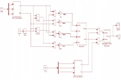
2. Over all Simulation Diagram withUnsymmetrical Fault
The modelling of the system with flexiblevoltage support control is designed in simulink. Thegain parameters of flexible voltage support controllerobtained by proper tuning. Flexible voltage supportcontrol works as a regulator of the voltage and currentduring transition from grid connected toUnsymmetrical Fault. α and β for flexible voltagesupport control is chosen proper tuning. The overallSimulation Diagram with Flexible Voltage Supportcontroller fig.4.
Fig.4 Simulation Diagram withUnsymmetrical Fault
3. Grid Voltage and current for symmetrical fault
The grid voltage and current waveformswithout fault is shown Fig.6. The grid voltage is 565Vand current value is 25A.
Fig.5 Grid Voltage and Current forsymmetrical Fault
The Fig.5 shows the voltage and current valueof grid and interconnection of solar power plant andthree phase conventional source. In the Fig.5normal condition the voltage and current values arecalculated by using voltage current measurement. Innormal condition with any disturbances grid voltagevalue 400V and current value is 38A in grid.
4. Grid Voltage and current forUnsymmetrical fault
The grid voltage and current waveformswithout fault is shown Fig. 6. The grid voltage is 560Vand current value is 40A.The Fig.6 shows the voltageand current value of grid and interconnection of solarpower plant and three phase conventional source.
Fig.6 Grid Voltage and Current forsymmetrical Fault
Inthe Fig 6, Unsymmetrical condition the voltage andcurrent values are calculated by using voltage currentmeasurement. Here R&Y phases are fault condition.The grid voltage value in RY&B phases -565V perphase and grid current value in B phase 40A in R&Yphases 38A. So reduces the fault current values with inlimit using reactive power injection in normalcondition.
IV. CONCLUSION
The voltage supportstrategy can be modified by means of a controlparameter according to the type of voltage sag. In threephase balanced sags, the best solution seems to be toraise the voltage in all phases. In one or two-phasefaults,
voltage equalization is a preferred choicebecause
conventional strategies can lead to overvoltageand cause disconnection. When the sag is less deep, abalance between these two extreme policies should beimplemented.
REFERENCES
[2] R. C. Dugan and T. E. McDermott, ―Distributedgeneration, IEEE Ind.Appl. Mag., vol. 8, no. 2, pp. 19–25,Mar./Apr. 2002.
[3] R. H. Lasseter, ―Microgrids and distributed generation, J.EnergyEng.,vol. 133, no. 3, pp. 144–149, Sep. 2007.
[4] C. Mozina, ―Impact of green power
distributedgeneration, IEEE Ind.Appl. Mag., vol. 16, no. 4, pp. 55–62,Jul./Aug. 2010.
[5] IEEE Recommended Practice for Utility Interface ofPhotovoltaic(PV)Systems, IEEE Standard 929-2000, 2000.
[6] IEEE Standard for Interconnecting Distributed Resourceswith ElectricPower Systems, IEEE Standard 1547-2003, 2003.
[7] J. Stevens, R. Bonn, J. Ginn, and S.
Gonzalez,Development and Testingof an Approach to Anti-Islanding inUtility-Interconnected PhotovoltaicSystems. Livermore, CA, USA: Sandia National Laboratories,2000.
[8] A. M. Massoud, K. H. Ahmed, S. J. Finney, and B.
W.Williams, ―Harmonicdistortion-based island
detectiontechnique for inverter-based distributedgeneration, IET Renewable Power Gener., vol. 3, no. 4, pp.493–507, Dec. 2009.
[9] T. Thacker, R. Burgos, F. Wang, and D. Boroyevich,Single-phase islanding detection based on phase-locked loopstability, in Proc. 1st IEEEEnergy Convers. Congr.Expo., San Jose, CA, USA, 2009, pp.3371– 3377.
[10] K. Kim, J.-H.Jeon, J.-B.Ahn, B. Lee, and S.-H.Kwon, ―Frequencyshift acceleration control for anti-islandingof a distributed-generation inverter,IEEE Trans. Ind.Electron., vol. 57, no. 2, pp. 494–504, Feb. 2010.
[11] A. Yafaoui, B. Wu, and S. Kouro, Improved activefrequency drift antiislanding detection method for
gridconnected photovoltaic systems, IEEE Trans.
PowerElectron., vol. 27, no. 5, pp. 2367–2375, May 2012.
[12] J. M. Guerrero, L. Hang, and J. Uceda, Control
ofdistributed uninterruptible power supply systems,
IEEETrans. Ind. Electron., vol. 55, no. 8, pp. 2845–2859, Aug.2008.
[13] M. C. Chandorkar, D. M. Divan, and R. Adapa,
Controlof parallel connected inverters in
standaloneACsupplysystems,IEEE Trans. Ind. Appl., vol. 29, no. 1, pp. 136–143,Jan./Feb. 1993.
[14] Y. Li, D. M. Vilathgamuwa, and P. C. Loh, Design,analysis, and realtime testing of a controller for multibusmicrogrid system, IEEE Trans. Power Electron., vol. 19, no.5, pp. 1195–1204, Sep. 2004.
Authors Details:
Vuppari Prabhakar Completed M.Tech(Energy Systems) from JNTUCEA.
S.Vijay Kumar completed M.Tech(Digital Systems And Computer Electronics) from JNTUH