CORDIC Algorithm based Sine and Cosine
Generator
A. M. Borkar1, A. S. Baradkar2, A. D. Bhonde3, P. B. Kude4, S. D.Kale5, R. J.Giri6
Assistant Professor, Dept. of ECE, DBACER Nagpur, India1 UG Student, Dept. of ECE, DBACER, Nagpur, Maharashtra, India2 UG Student, Dept. of ECE, DBACER, Nagpur, Maharashtra, India3 UG Student, Dept. of ECE, DBACER, Nagpur, Maharashtra, India4 UG Student, Dept. of ECE, DBACER, Nagpur, Maharashtra, India5 UG Student, Dept. of ECE, DBACER, Nagpur, Maharashtra, India6
ABSTRACT: This paper presents an innovative scaling-free CORDIC algorithm in rotation mode for hyperbolic trajectory. We employ most-significant-1 bit revealing method for micro-rotation sequence generation to reduce the number of iterations. The CORDIC algorithmic is an iterative analyzing algorithm capable of evaluate various elementary functions using a combined shift and add approach Used to calculate a wide variety of functions. It consists of structure containing pipelining with internal structure of block. This paper presents mode of operation and control CORDIC algorithm. The product has been revealed in this paper that resolution of CORDIC algorithm is finest for implementing many trigonometrically functions.
KEYWORDS: CORDIC, Rotation Mode, Pipelining, Adder, Subtractor, D-flip-flop.
I.INTRODUCTION
The CORDIC algorithm was first introduced by Jack E. Volder in the year 1959 for the computation of Trigonometric functions, Multiplication, Division, Data type conversion, Square Root and Logarithms. It is a highly efficient, low-complexity and robust technique to compute the elementary functions. The CORDIC algorithm has found its way in various applications such as pocket calculators, numerical co-processors, to high performance radar signal processing, supersonic bomber aircraft with a digital counterpart. The algorithm performs the operation in sequential mode. The CORDIC algorithm requires only shifts, adders, and table lookups, simple integer math. The mode of operation is simple and easy to implement on the hardware.
Nowadays the most of the applications are based on real time results and exchange of information revolves around transmission. The algorithm eliminates the use of unambiguous multipliers and suitable for calculating a variety of functions, such as sine, co-sine, arc-tangent, hyperbolic and logarithmic functions. In this paper the CORDIC results are obtained through the VHDL. The calculation of the sine and cosine is done by rotation method of the algorithm. so it is possible to implement a CORDIC machine slow and fast enough to dedicate for one purpose. In this paper the 16 bit value is given as an input which gives the sine and cosine of the particular input. The output is studied in the form of waveform. The rest of the paper is organized into various sections containing the method, detail of the algorithm and the studied conclusion of the sine and cosine generation.
Vol. 5, Issue 4, April 2016
additions, subtractions, digit shifts, comparisons and stored constants. Today cordic algorithm is used in Neural Network VLSI design, high performance vector rotation DSP applications, advanced circuit design, optimized low power design. CORDIC algorithm revolves around the idea of "rotating" the phase of a complex number, by multiplying it by a succession of constant values. However, the "multiplies" can all be powers of 2, so in binary arithmetic they can be done using just shifts and adds; no actual "multiplier" is needed thus it simpler and do not require complex hardware structure as in the case of multiplier. Earlier methods used are Table look up method, Polynomial approximation method etc. for evaluation of trigonometric functions. It is hardware efficient algorithm.
II. DESCRIPTION OF CORDIC ALGORITHM
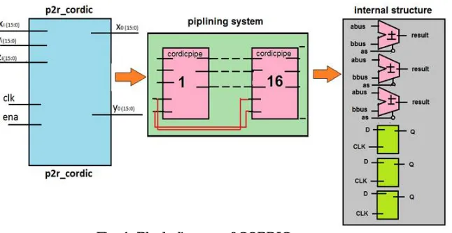
Fig. 1: Block diagram of CORDIC processor
This is the generalized block diagram of the CORDIC processor which shows the three main module of the algorithm. The first block represents the main processor of the algorithm which includes the input and output ports. The second block represents the pipelining of the processor. The third block gives us the information about the internal block diagram of the each block in the pipelining.
III.CORDIC ALGORITHM
All of the trigonometric functions can be evaluated and obtained through the vector rotation method. A vector with the certain angle is rotated and the obtained equation can be written as,
x’= x cosØ - y sinØ and y’= y cosØ + x sinØ This rotates a vector in plane by the angle Ø Now after the rotation the previous equation can be rewrite as,
x’= cosØ * [x- y tanØ ] and y’= cosØ * [y +x tanØ ]
Fig. 2: Rotation of vector by given angle
X(i+1)= Ki [xi – yi × di × 2-i ] and Y(i+1)= Ki [yi + xi × di × 2-i ] where, Ki = COS (tan -12-i) = 1/ i 212 and di= 1
The Ki can be represented as the part of system processing gain. The product approaches 0.61 as the number of iteration
goes to infinity. Therefore the rotation algorithm has a gain an of approximately 1.65. The precise gain depends on the no of iterations and obeys the relation.
The angle of a complex rotary motion is distinctively definite by the chain of the directions of the elementary rotations. That sequence can be represented by a verdict vector. The set of all possible decision vectors is an angular measurement system based on binary arctangents: Z (i+1)= zi – di× tan -1(2–i)
The elementary angles can be expressed in any convenient angular unit. Those angular standards are supplied by a miniature look up table or are hardwired depending on the application. The angle accumulator sum up 3rd difference equation to the CORDIC algorithm. Obviously, in cases where the angle is useful in the arc tangent base, this extra element is not needed. The CORDIC rotator is normally operated in one of two modes. The first called rotation by Volder rotates the input vector by a specified angle. The second mode called vectoring rotates the input vector to the x axis while recording the angle required making that rotation.
Rotation Mode:
In the rotational mode, the vector magnitude and an angle of rotation are known and the coordinate (X-Y) components are computed after rotation mode. The CORDIC begins by initializing an angle collector with the desired angle. Next his rotation conclusion at each CORDIC iteration is done in way that decreases the magnitude of the lasting angle. The rotation decision is based on the sign of the enduring angle in the angle accumulator after each iteration.
For rotation mode, the CORDIC equations are:
X(i+1) = xi – yi × di × 2-i, Y(i+1) = yi + xi × di × 2-i and Z(i+1) = zi – di × tan -1(2 –i)
where, di = -1 if zi < 0 and +1 otherwise
This provides the following result, xn = An[x0 cosz0 – yo sin z0], yn = An[yo cosz0 + x0 sinz0] and zn = 0
In rotation mode, the CORDIC algorithm is limited to rotation angles between –π/2 to π/2. To support angles outside of the range, quadrant correction is often used.
Sine and Cosine of CORDIC Operation:
The CORDIC operation simultaneously computes sine and cosine of input angle. xn = An × x0 cos z0 and yn = An × x0 sin z0
By setting xo equal to 1/An rotation produces the unscaled sine and cosine of the angle disagreement zo.Very regularly the sine and cosine values modulate a magnitude. Using other techniques requires a no. of multipliers to obtain the modulation. The CORDIC operation performs the multiply as part of the rotation operation and therefore eliminates the need for a pair of obvious multipliers. The output of the CORDIC rotator is scaled by the rotator gain. If the gain is not acceptable, a single multiply by the reciprocal of the gain constant placed before the CORDIC rotator will yield the unscaled results. It is worth noting that the hardware difficulty of the CORDIC rotator is approximately equivalent to that of a single multiplier with the same word size.
Polar to Rectangular Transformation:
Vol. 5, Issue 4, April 2016
accounted somewhere in the system. If the gain is unacceptable the polar amount may be multiplied by the reciprocal of the rotator gain before it is presented to the CORDIC rotator.
Analysis of Error:
There are two types of error encountered during the rotation mode CORDIC iterations. Those are: estimate error and round-off error. Estimate error arises due to estimate of angle of rotation and scaling factor, although the round- off error comes due to the finite word-length of the output components. We derive the expression for these couple errors in the next subsections
Fig. 3: Rotation mode CORDIC iterations Approximation of Error:
Proposed CORDIC operation and approximation inaccuracy elaborate the CORDIC iteration which consists of a pseudo-micro- rotations and a scaling. In the figure, is an key in vector to be spin through angle ø. It is assumed that scaling and micro- rotations are implement in 2 separate stages.P-1 be the spined vector after m-1 micro-rotations given by
The rotation matrix R(i) is given by (3). The i th measuring factor is specified by
Such that after m2 iterations of scaling we get
After the micro-rotations, there is a incongruity Δø among the preferred angle and the resultant angle due to the limited number of micro-rotations. Likewise, P-1 cannot attain P on the circle following the measuring since KA is an estimated worth which is not equivalent as the vital K. Alike to the technique used, the estimated error is evaluated as a distance between the chosen output V and the actual CORDIC output P-2 as follows
For the recognized and predetermined angle, an anticipation of the approximation error can be estimated once we know the input statistics as
IV.SIMULATION RESULT
Fig. 4: RTL Schematic
Fig. 5: RTL internal structure of the p2r CORDIC Algorithm
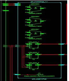
Fig. 6: Internal structure of pipelining
Final output of the CORDIC Algorithm:
Vol. 5, Issue 4, April 2016
V.CONCLUSION
This paper has presented the different architecture of the CORDIC algorithm with the rotation method. The programming of the CORDIC is done in VHDL.CORDIC algorithm mostly suitable for the calculation of the trigonometric function. In this paper the value of the sine and cosine is calculated and the waveform is studied. The CORDIC algorithm issignal and image processing, digital communication, robotics and 3-D graphics.
REFERENCES
[1] J.E Volder,” the CORDIC trigonometric computing technique”,IRE transactions on electronic computer,vol. EC-8,pp. 330-334,1959 [2] V.Naresh , B.Venkataramani and R.Raja , “An area efficient multiplexer based CORDIC”, National Institute of Technology,
Tiruchirappalli,India
[3] Supriya Aggarwal, Pramod Kumar Meher,Senior Member, IEEE, and Kavita Khar, “Scale-Free Hyperbolic CORDIC Processor and Its Application to Waveform Generation” IEEE transactions on circuits and systems- I : regular papers,vol.60,no.2,February
[4] Andraka,R.J., “building a high performance bit-serial processor in an FPGA,”proceedings of design supercon’96,jan 1996,pp5.1-5.21. [5] Pramod K.Meher, Senior Member ,IEEE, Javier Valls, Member, IEEE, Tso- Bing Juang , Member, IEEE, K.Sridhan, Senior Member, IEEE,