Available online:
https://edupediapublications.org/journals/index.php/IJR/
P a g e | 1475Design and implementation of Grid-Connected PV
system based Multilevel Inverter with distributed
MPPT for Fuzzy logic Controller
D.V.Sas id h ar M-tech Student Scholar
Department of Electrical & Electronics Engineering, BVC institute of science & technology, Amalapuram;
East Godavari (Dt); A.P, India.
K.V.V.Saty an aray an a Assistant Professor
Department of Electrical & Electronics Engineering, BVC institute of science & technology, Amalapuram;
East Godavari (Dt); A.P, India.
Abstract-This p ap er int roduces a p art icular fell H -sp an multilevel photovoltaic (PV) invert er for t hree p hase grid-connected applications. The measured fell multilevel t op ology enhances the proficiency and adaptability of PV sy st ems. T o acknowledge better use of PV modules and maximize the solar energy extraction, a disp ersed most ext reme p ower p oint following control plan is connected to both single-and t hree-p hase multilevel inverters, which hree-permits indehree-pendent control of each dc-link volt age. For t hree-p hase grid-connect ed applications, PV mismat ches may int roduce unbalanced supplied power, driving to unequal matrix current. A test three-p hase multi level fell H-sthree-pan inverter has been fabricated using nine H-span modules. Fuzzy Logic based Intelligent Controller has been imp lement ed for volt age regulat ion at Point of Common Coupling of Grid connected PV Power Sy st em. T o realize better utilization of PV modules and maximize the solar energy extraction, a distributed maximum power point tracking control scheme is applied t o bot h single- and t hree-p hase multilevel inverters, which allows independent control of each dc-link voltage. The proposed grid connected Power System has been designed and analy z ed in M AT LAB Simulink environment .
Index Terms —cascaded mult ilevel invert er, dist ribut ed maximum power point (MPP) t racking (M PPT ), modular, modulat ion Comp ensat ion.
I. INTRODUCTION
In recent years, the efforts to spread the use of renewable energy resources instead of pollutant fossil fuels and other forms have increased. Photovoltaic systems offer the possibility of converting sunlight into electricity. The transformation of electricity through photovoltaic provides case of installation, maintenance and become more affordable.
Due to the shortage fossil powers and ecological issues brought on by traditional power generation, renewable energy, especially solar energy, has turned out to be exceptionally prominent. Solar electric-energy request has become reliably by 20%–25% for each annum in the course of recent years, and the development is for the
most part in grid-connected applications. With the exceptional market development in network connected photovoltaic (PV) systems [1-2], there are expanding interests in grid-connected PV designs. Five inverter families can be characterized, which are identified with distinctive designs of the PV system: 1) focal inverters; 2) string inverters; 3) multistring inverters; 4) air conditioning module inverters; what's more, 5) fell inverters. The designs of PV systems are appeared in Fig1. Cascaded inverters consist of several converters connected in series; in this manner, the high power and/or high voltage from the blend of the various modules would support this topology in medium and vast grid-connected [3-4] PV systems.
Energy crisis leading to energy demand across the globe force us to switch to other sources of energy. Renewable Energy sources prefer more due to their less carbon emission. In the countries of the equatorial region solar energy is abundant, so Photovoltaic Power Systems are the commonly used renewable energy. Considering various different cases, Multilevel Inverters play major role in the Power Quality improvement in renewable energy power systems [5-6]. For maximum utilization distributed power systems are the most suitable in photovoltaic power systems. Cascaded H-Bridge type multilevel inverters are the appropriate one for the distributed photovoltaic power system. Fuzzy logic based intelligent controller is used n continuous monitoring of the grid connected photovoltaic power system and controlling the cascaded H-bridge inverter.[7] Block diagram representing the grid connected photovoltaic power system.
Available online:
https://edupediapublications.org/journals/index.php/IJR/
P a g e | 1476trading of energy and power is becoming increasingly important.
The modular cascaded H-bridge multilevel inverter, [9] which requires an isolated dc source for every H-bridge, is one dc/ac cascaded inverter topology. The different dc links in the multilevel inverter make autonomous voltage control conceivable [10]. As an outcome, individual MPPT control in each PV module can be accomplished, and the energy reaped from PV panels can be maximized. In the interim, the particularity and ease of multilevel converters would position them as a prime hopeful for the up and coming generation of efficient, robust, and reliable grid connected solar power electronics [11]. A measured cascaded H-bridge multilevel inverter topology for single-or three-phase grid connected PV systems is exhibited in this paper. The panel losses issues are tended to demonstrate the need of individual MPPT control, and a control plan with circulated MPPT [12] control is then proposed. The distributed MPPT control plan can be connected to both single and three phase systems. What's more, for the introduced three-phase grid connected PV system, if each PV module is worked at its own particular MPP, PV losses may acquaint unequal power supplied with the three-phase multilevel inverter, prompting introduce unbalanced grid current [13]. To adjust the three-phase grid current, modulation compensation is additionally added to the control system.
II. SYSTEM DESCRIPTION
Modular cascaded H-bridge multilevel inverters for single and three-phase grid-connected PV systems are shown in Fig.1. Each phase consists of n H-bridge converters connected in series, and the dc link of each H-bridge can be fed by a PV panel or a short string of PV panels. The cascaded multilevel inverter is connected to the grid through L filters, which are used to reduce the switching harmonics in the current.
By different combinations of the four switches in each H-bridge module, three output voltage levels can be generated: −vdc, 0, or +vdc. A cascaded multilevel inverter with n input sources will provide 2n + 1 levels to synthesize the ac output waveform. This (2n + 1)-level voltage waveform enables the reduction of harmonics in the synthesized current, reducing the size of the needed output filters. Multilevel inverters also have other advantages such as reduced voltage stresses on the semiconductor switches and having higher efficiency when compared to other converter topologies.
III. PA NEL M ISM A TCHES
PV mismatch is an important issue in the PV system. Due to the unequal received irradiance, different temperatures, and aging of the PV panels, the MPP of each PV module may be different. If each PV module is not controlled independently, the efficiency of the overall PV system will be decreased.
To show the necessity of individual MPPT control, a five-level two-H-bridge single-phase inverter is simulated in MATLAB/SIMULINK. Each H-bridge has its own 185-W PV panel connected as an isolated dc source. The PV panel is modeled according to the specification of the commercial PV panel from Astronergy CHSM-5612M. Consider an operating condition that each panel has a different irradiation from the sun; panel 1 has irradiance S =1000 W/m2, and panel 2 has S = 600 W/m2. If only panel 1 is tracked and its MPPT controller determines the average voltage of the two panels, the power extracted from panel 1 would be 133 W, and the power from panel 2 would be 70 W, as can be seen. Without individual MPPT control, the total power harvested from the PV system is 203 W.
However, the MPPs of the PV panels under the different irradiance. The maximum output power values will be 185 and 108.5 W when the S values are 1000 and 600 W/m2, respectively, which means that the total power harvested from the PV system would be 293.5 W if individual MPPT can be achieved. This higher value is about 1.45 times of the one before. Thus, individual MPPT control in each PV module is required to increase the efficiency of the PV system.
Available online:
https://edupediapublications.org/journals/index.php/IJR/
P a g e | 1477Fig. 1. T opology of the modular cascaded H-bridge multilevel inverter for grid-connected PV systems.
To solve the PV mismatch issue, a control scheme with individual MPPT control and modulation compensation is proposed. The details of the control scheme will be discussed in the next section.
IV. CONTROL SCHEM E A .Dis tributed MPPT Control
In order to eliminate the adverse effect of the mismatches and increase the efficiency of the PV system, the PV modules need to operate at different voltages to improve the utilization per PV module.
The separate dc links in the cascaded H-bridge multilevel inverter make independent voltage control possible. To realize individual MPPT control in each PV module, the control scheme proposed is updated for this application. The distributed MPPT control of the three-phase cascaded H-bridge inverter is shown in Fig.2. In each H-bridge module, an MPPT controller is added to generate the dc-link voltage reference. Each dc-dc-link voltage is compared to the corresponding voltage reference, and the sum of all errors is controlled through a total voltage controller that determines the current reference Idref. The reactive current
reference Iqref can be set to zero, or if reactive power compensation is required, Iqref can also be given by a reactive current calculator. The synchronous reference frame phase-locked loop (PLL) has been used to find the phase angle of the grid voltage. As the classic control scheme in three-phase systems, the grid currents in abc coordinates are converted to dqcoordinates and regulated through proportional–integral (PI) controllers to generate the modulation index in the dqcoordinates, which is then converted back to three phases.
The distributed MPPT control scheme for the single-phase system is nearly the same. The total voltage controller gives the magnitude of the active current reference, and a PLL provides the frequency and phase angle of the active current reference. The current loop then gives the modulation index.
To make each PV module operate at its own MPP, take phase a as an example; the voltages vdca2 to vdcanare controlled individually through n − 1 loops. Each voltage controller gives the modulation index proportion of one H-bridge module in phase a. After multiplied by the modulation index of phase a, n − 1 modulation indices can be obtained. Also, the modulation index for the first H-bridge can be obtained by subtraction. The control schemes in phases b and c are almost the same. The only difference is that all dc-link voltages are regulated through PI controllers, and n modulation index proportions are obtained for each phase.
Fig.2. Control scheme for three-phase modular cascaded H-bridge multilevel PV inverter.
A phase-shifted sinusoidal pulse width modulation switching scheme is then applied to control the switching devices of each H-bridge.
Available online:
https://edupediapublications.org/journals/index.php/IJR/
P a g e | 1478 subtraction. For single-phase systems, N = n, and forthree-phase systems, N = 3n, where n is the number of H-bridge modules per phase. The reason is that N voltage loops are necessary to manage different voltage levels on N H-bridges, and one is the total voltage loop, which gives the current reference. So, only N − 1 modulation indices can be determined by the last N – 1 voltage loops, and one modulation index has to be obtained by subtraction.
Many MPPT methods have been developed and implemented. The incremental conductance method has been used in this paper. It lends itself well to digital control, which can easily keep track of previous values of voltage and current and make all decisions.
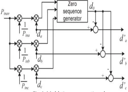
B. Modulation Compens ation
As mentioned earlier, a PV mismatch may cause more problems to a three-phase modular cascaded H-bridge multilevel PV inverter. With the individual MPPT control in each H-bridge module, the input solar power of each phase would be different, which introduces unbalanced current to the grid. To solve the issue, a zero sequence voltage can be imposed upon the phase legs in order to affect the current flowing into each phase. If the updated inverter output phase voltage is proportional to the unbalanced power, the current will be balanced.
Thus, the modulation compensation block, as shown in Fig. 3, is added to the control system of three-phase modular cascaded multilevel PV inverters. The key is how to update the modulation index of each phase without increasing the complexity of the control system. First, the unbalanced power is weighted by ratio rj, which is calculated as
Fig. 3. Modulation compensation scheme.
(1)
Where Pinjis the input power of phase j (j = a, b, c), and Pinav is the average input power.
Then, the injected zero sequence modulation index can be generated as
(2)
Where djis the modulation index of phase j (j = a, b, c) and is determined by the current loop controller.
The modulation index of each phase is updated by
(3)
Only simple calculations are needed in the scheme, which will not increase the complexity of the control system. An example is presented to show the modulationcompensation scheme more clearly. Assume that the input power of each phase is unequal
(4) V.FUZZY LOGIC CONTROL
L. A. Zadeh presented the first paper on fuzzy set theory in 1965. Since then, a new language was developed to describe the fuzzy properties of reality, which are very difficult and sometime even impossible to be described using conventional methods. Fuzzy set theory has been widely used in the control area with some application to power system [5]. A simple fuzzy logic control is built up by a group of rules based on the human knowledge of system behavior. Matlab/Simulink simulation model is built to study the dynamic behavior of converter. Furthermore, design of fuzzy logic controller can provide desirable both small signal and large signal dynamic performance at same time, which is not possible with linear control technique. Thus, fuzzy logic controller has been potential ability to improve the robustness of compensator.
Available online:
https://edupediapublications.org/journals/index.php/IJR/
P a g e | 1479control rules and linguistic variable definitions; a de-fuzzification interface which yields non-fuzzy control action from an inferred fuzzy control action [10].
Fig.4.Block diagram of the Fuzzy Logic Controller (FLC) for Proposed Converter.
Fig.5. Membership Functions for Error.
Fig.6. Membership functions for change_in_error.
Fig.7. Membership functions for Output. T able II
T able rules for error and change of error.
VI.M TA LA B/SIM ULA TION RESULTS
Fig.8.Matlab/Simulation model of the modular cascaded H-bridge multilevel inverter for grid-connected PV systems.
Available online:
https://edupediapublications.org/journals/index.php/IJR/
P a g e | 1480 (b)(c)
Fig. 9. DC-link voltages of phase a with distributed MPPT (T = 25 ◦C). (a) DC-link voltage of modules 1. (b) DC-link voltage of module 2.
(c).DC-link voltage of module 2.
Fig.10. PV currents of phase a with distributed MPPT (T = 25 ◦C).
Fig.11. DC-link voltages of phase b with distributed MPPT (T = 25 ◦C).
Fig.12. Power extracted from PV panels with distributed MPPT .
Available online:
https://edupediapublications.org/journals/index.php/IJR/
P a g e | 1481 Fig. 14. T hree-phase grid current waveforms with modulationcompensation.
Fig. 15. T hree-phase inverter output voltage waveforms with modulation Compensation.
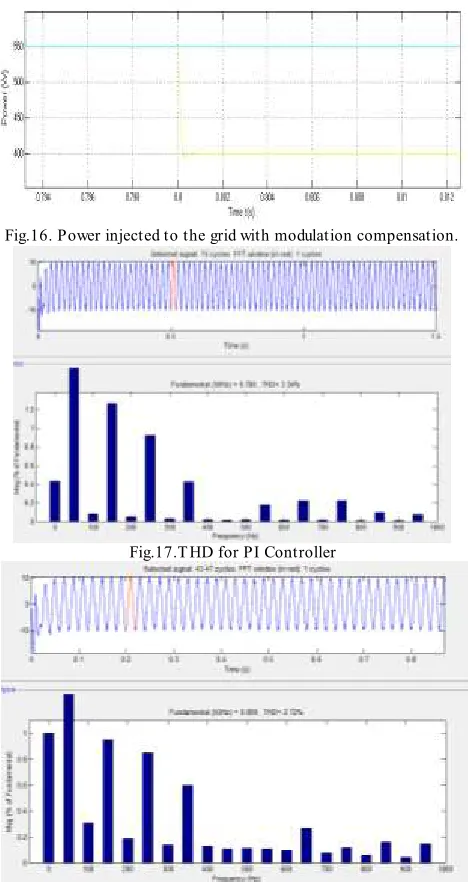
Fig.16. Power injected to the grid with modulation compensation.
Fig.17.T HD for PI Controller
Fig.18.T HD for Fuzzy logic controller.
VII.CONCLUSION
Available online:
https://edupediapublications.org/journals/index.php/IJR/
P a g e | 1482system, PV crisscrosses may present lopsided supplied power, bringing about unequal infused system current. With the proposed control conspire; each PV module can be worked at its own particular MPP to augment the solar energy extraction, and the three-phase system current is adjusted even with the unequal supplied solar based power. And finally by observing the THD values this system gives better performance when fuzzy controller was used. The power extracted from the PV array increased by the fuzzy based MPPT which develop the system performance in varying weather condition.
REFERENCES
[1] J. M. Carrasco et al., ―Power-electronic systems for the grid integration of renewable energy sources: A survey,‖ IEEE T rans. Ind. Electron., vol. 53, no. 4, pp. 1002–1016, Jun. 2006.
[2] S. B. Kjaer, J. K. Pedersen, and F. Blaabjerg, ―A review of single-phase grid connected inverters for photovoltaic modules,‖ IEEE T rans. Ind. Appl., vol. 41, no. 5, pp. 1292– 1306, Sep./Oct. 2005. [3] M. Meinhardt and G. Cramer, ―Past, present and future of grid connected photovoltaic- and hybrid power-systems,‖ in Proc. IEEE PES Summer Meet., 2000, vol. 2, pp. 1283–1288.
[4] M. Calais, J. Myrzik, T. Spooner, and V. G. Agelidis, ―Inverter for single-phase grid connected photovoltaic systems—an overview,‖ in Proc. IEEE PESC, 2002, vol. 2, pp. 1995–2000
[5] Vasarevičius D., Martavičius R. Solar Irradiance Model for Solar Electric Panels and Solar T hermal Collectors in Lithuania // Electronics and Electrical Engineering. – Kaunas: Technologija, 2011. – No. 2(108). – P. 3–6.
[6] T . Shimizu, M. Hirakata, T. Kamezawa, H. Watanabe, “Generation control circuit for photovoltaic modules”, IEEE trans. on power electronics, vol. 16, no. 3, pp. 293-300, May 2001.
[7] H. Watanabe, T . Shimizu, G. Kimura, “A novel utility interactive Photovoltaic inverter with generation control circuit”, IEEE proc. Of 24th IECON, vol. 2, pp. 721-725, August - September 1998, Germany. [8] A. Chaouachi, R. M. Kamel, K. Nagasaka, “A novel multi-model neuro-fuzzy-based MPPT for three-phase grid-connected photovoltaic system”. Solar Energy 2010;84(12):2219-2229.
[9] N. Hamrouni, M. Jraidi, A. Chérif, “New control strategy for 2-stage grid-connected photovoltaic power system”. Renewable Energy, vol. 33, no 10 pp. 2212-2221, 2008.
[10] S-K Kim, J-K Jeon, C-H Cho, E-S Kim, J-B Ahn, “Modeling and simulation of a grid-connected PV generation system for electromagnetic transient analysis”. Solar Energy, vol. 83, No 5, pp. 664-678, 2009.
[11] B. Yu, M. Matsui, Y. Jung, G. Yu, “A combined active anti-islanding method for photovoltaic systems”. Renewable Energy, vol. 33, No 10, pp. 979-985, 2008.
[12] A. Menti, T . Zacharias, J. Milias-Argitis, “Harmonic distortion assessment for a single-phase grid-connected photovoltaic system”. Renewable Energy, vol. 36, No 1, pp. 360-368, 2011
[13] A. Nabae, I. T akahashi, and H. Akagi, “A new neutral-point clamped PWM inverter,” IEEE T ransactions Industry Applications, vol. IA-17, no. 5, pp. 518-523, Sep./Oct. 1981.