Fuzzy Logic Controller Based Performance Analysis of
Autonomous Pv-Array Excited Wind-Driven Induction
Generator
#1Dr.A.MALLIKARJUNA PRASAD, Associate Professor, Vardhaman College Of
Engineering, Shamshabad, [email protected]
#2
UTUKURU CHAITHANYA ,Assistant Professor,G.Pullaiah College Of Engineering,
Kurnool, [email protected]
#3
Dr,THIRU M.VELUSWAMY, Visiting Professor, Annamalai University, Annamalai
Nagar, Chidambaram
ABSTRACT: This paper content the hybrid scheme generation uses wind and pv system in the expeditious growth of power electronics techniques which makes the viability for the better utilization of power. For the utility grid or to an isolated load, the renewable energy system can be used to provide power directly. Further, the stand alone system find the vast utilization as water pumps, for village electrification, supply of power to an isolated areas which are far away from the utility grid. Overall, fully- controlled wind turbine & pv techniques, are often compatible as the sunlit days are generally serene & strong winds are literally occurs on cloudy days. To improve the generating performance &implementation of power utilization, the hybrid PV-wind system has higher scope to distribute continuous power for better result than compare to individual sources. On the contrary side, PV hybrid system has environmental assets such as reduction of carbon emission due to use of renewable energy resources. The stand-alone wind power generation with the self-excited generator comprises of dynamically variable reactive power to control constant output voltage. But in the proposed scheme of PV hybrid scheme by replenishing the 3 phase fixed frequency PWM inverter fed from the PV array the mandatory reactive power under varying rotor speed can be accomplished. This paper describe the advance fuzzy logic controller to vary the duty cycle of DCDC converter such as to support the load voltage constant under varying rotor speed or load.
Index Terms— Index Terms— off gird, PV, wind, wind driven induction generator
1. INTRODUCTION
Centralized power generation systems are facing the twin constraints of shortage of fossil fuel and need to reduce the emissions. Long distance transmission line are one of the main causes for electrical power losses. So, emphasis has increased on distributed generation (DG) networks with integration of renewable energy systems into the national grid, which lead to efficiency and reduction in emissions. With the rise of the
inherent complimentary profile, it becomes an attractive choice for a hybrid renewable energy scheme.Many hybrid schemes have been already reported in literature as well as exists in practice [1] – [4].Normally in hybrid wind-solar schemes,
PMSG (permanent magnet Synchronous
generators), is invariably used as the wind driven generator especially for a standalone applications [5]- [10]. In such hybrid schemes based on PV and wind driven PMSG, the varying amplitude varying frequency of the stator voltage of the PMSG and the variable dc voltage of the PV array have to be suitably conditioned using complex power-electronic interfaces. However, for any off-grid system, it is desirable to install components and their associated controls that are maintenance free and economical. In this context, Self excited induction generators using capacitors have been reported in the literature [11]-[12].Squirrel Cage Induction Generator (SCIG) which is robust, inexpensive, require little maintenance and possess higher power-weight ratio over PMSG, much cheaper than PMSG would be desirable choice for a remotestandaloneapplication. But despite these advantages,wind-drivencapacitor-excited induction generators are not preferred in remote power systems due to their unsatisfactory voltage regulation and frequency variation .However to exploit the advantages of IG as well as to overcome the above drawback, hybrid system employing a dc-dc converter fed 3-phase Voltage Source inverter (VSI) as power interface stage, battery charged by solar photo voltaic cells (PV) and the PV excited Induction Generator (IG) driven by wind have been reported in the literature[10]. The three phase Load, output of IG and output of the VSI forms a Point of Common Coupling (PCC). This hybrid scheme can operate to supply the required load even in the absence of battery [11]. However in this work, a fixed resistive load has been considered for the controller design as well as unbalance in load has not been considered. Further to this, hybrid scheme based on PV and IG reported in the literature [15]-[16], need a utility grid for its operation. Most of them employ a doubly fed induction generator [17]-[18], which is once again expensive [19]-[21]. It is attempted to develop a robust and reliable control scheme for autonomous hybrid system based on PV source and wind driven induction generator that can provide continuous regulated three phase output voltage for all types of load with or without unbalance. In the present work, a simplified controller for battery less mode operation has been developed for a PV fed Boost Converter fed Inverter excited wind driven IG scheme (PVEWIG) to regulate the inverter DC link in the absence of battery. In this scheme, a three phase variable resistive as well as inductive load with or without unbalance has been considered. The proposed controller ensures voltage regulation
of DC link and improves the power quality parameters at point of common coupling (PCC) under varying irradiation, temperature of PV array and wind speed variation in the wind generator
.
II. THE PV ARRAY FED INVERTER EXCITED WIND DRIVEN IG
The PVEWIG system consists of PV array, dc-dc converter, battery, 3 leg inverter, wind driven three phase squirrel cage induction generator and a non-linear load. The PV array feeds a dc-dc boost converter. The voltage across the dcdc boost converter is connected to a battery, which is inverted by a three phase inverter and the IG is integrated to the inverter output and is locked to inverter voltage and frequency. The IG would require reactive power which it would normally draw from a utility grid in a grid connected scheme. In the present scheme, the reactive power required by the induction machine is supplied by the PV array fed inverter. The output of the inverter acts as a virtual grid providing a constant voltage and frequency. The three-phase load is connected to inverter output and is supplied by PV-IG and battery or PV-IG, the load-sharing being dependent on irradiation and wind speed. The inverter output, IG output and load forms the point of common coupling (PCC). The block schematic of the entire PVEWIG scheme is shown in Fig. 1. One of the unique features of this hybrid scheme is that, this system employs an induction generator without a need of either utility grid or excitation capacitors, thereby avoiding all the disadvantages associated with it. In the absence of battery, the real power balance is such that the sum of PV array power and real power output of IG equals the inverter power output which is delivered to the load. The power balancing is explained in more detail in the subsequent sections.
III. CONTROL SCHEME OF THE PVEWIG
In this paper, battery less operation of the PVEWIG scheme has been considered. The system should continue to deliver power uninterrupted during the absence of battery, which might happen either due to deep discharge or fully charged condition of the battery. Also it might be necessary to remove the battery from the system for a brief duration for maintenance. In this mode, the boost converter will act in a voltage regulation mode and maintains constant DC link voltage under all conditions of weather and load changes. The Inverter is triggered by an open loop sinusoidal PWM controller. The control block diagram of the dc-dc boost converter used in this scheme is shown in Figure 2. The V-I characteristics of PV array varies with irradiation and temperature and this shifts the operating point of the PV array. Further, the variation of wind speed alters the shaft torque to the induction generator. These varying parameters cause the input as well as load of the dc-dc converter to vary. In this event, the controller works in voltage regulation mode. The dc-link voltage is regulated using a cascaded PI-SMC control in which the outer loop consists of a PI regulator and the inner loop consists of a sliding mode current controller (SMC) as shown in Fig. 2.
Figure 2 Block diagram of Cascaded PI-SMC controller for output voltage regulation of dc-dc
boost converter
The outer PI controller generates a current reference from its input voltage error between reference (Vo_ref) and actual output voltage (Vo) of dc-dc converter. The error between reference (IL_ref) and actual Inductor current (IL_act) is given as input to SMC which generates the gate pulse for the boost converter IGBT. The basic principle of SMC involves design of a sliding surface in its control law which would direct the trajectory of the state variables towards a desired origin. Normally in a single switch dc–dc converter, the control law that adopts a switching function is given by u 1 sign(S )where „u‟ is the switching function (logic state) of the converter‟s power switch and the state variable is the inductor current. Based on the general sliding mode control theory, the state variable error is defined as the difference between actual and reference value (of the inductor current), which
forms the sliding function given by
Sil_actualil_ref .
IV. FUZZY LOGIC
In recent years, the number and variety of applications of fuzzy logic have increased
significantly. The applications range from
consumer products such as cameras, camcorders, washing machines, and microwave ovens to industrial process control, medical instrumentation, decision-support systems, and portfolio selection. To understand why use of fuzzy logic has grown, you must first understand what is meant by fuzzy logic.
Fig.3 The Primary GUI Tools Of The Fuzzy Logic Toolbox
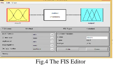
The FIS Editor handles the high level issues for the system How much input and output variables? What are their names? The Fuzzy Logic Toolbox doesn't limit the number of inputs. However, the number of inputs may be limited by the available memory of our machine. If the number of inputs is too large, or the number of membership functions is too big, then it may also be difficult to analyse the FIS using the other GUI tools. The Membership Function Editor is used to define the shapes of all the membership functions associated with each variable. The Rule Editor is for editing the list of rules that defines the behaviour of the system.
4.1The FIS Editor
The following discussion walks we through building a new fuzzy inference system from scratch. If we want to save time and follow along quickly, we can load the already built system by typing fuzzy tipper This will load the FIS associated with the file tipper. Is (the .fis is implied) and launch the FIS Editor. However, if we load the pre-built system, we will not be building rules and constructing membership functions.
Fig.4 The FIS Editor
now a new variable in the workspace called tipper that contains all the information about this system.
Fig.5 ‗Save to workspace as...‘ window By saving to the workspace with a new name, we also rename the entire system. Our window will look like as shown in Fig.5
Fig.6 The Updated FIS Editor
4.2 The Membership Function Editor
Fig. 7 The Membership Function Editor
Fig.8 Add MFs… Window
Fig.9 The Updated Membership Function Editor
4.3 The Rule Editor
Fig.10 The Rule Editor
Fig.11 Fuzzy rules
IV SIMULATION RESULTS
Fig 13 wind voltage and current under unbalanced
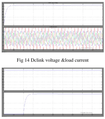
Fig 14 Dclink voltage &load current
Fig 15 Pv voltage ¤t
V.CONCLUSION
This paper proposes a fuzzy logic controller suitable for solar and wind hybrid energy conversion for isolated applications. The wind and solar hybrid power system is simulated using MATLAB.Fuzzy Logic MPPT Control is applied for wind and solar sources make the system efficient. The variations in duty-cycle to maintain constant load voltage with variations in irradiation and wind speed is achieved with the proposed fuzzy logic controller with optimized rulebase. Hybrid power system supplies AC and DC load so it is suitable for all applications like remote areas, villages and hill stations. In this paper, the output is taken one time with fuzzy logic controller and
another without. The output results shows that the using Fuzzy logic based system is more effective, energy management controller controls hybrid power system to provide uninterrupted power, minimizing usage of diesel, effective utilization of sources. Since the usage of diesel generator is minimized emission of harmful gases from it is minimized.
REFERENCES
[1]O. Honorati, G. L. Bianco, F. Mezzetti, and L. Solero, ―Power electronic interface for combined wind/PV isolated generating system,‖ in Proc. European UnionWind Energy Conf., Goteborg, Sweden, 1996, pp. 321– 324.
[2]B. S. Borowy and Z. M. Salameh. (1997, Mar.).Dynamic response of a stand-alone wind energy conversion system with battery energy storage to a wind gust. IEEE Trans. Energy Conversion.[On line]. 12(1), pp. 73–78. Available: DOI: 10.1109/60.577283.
[3]S. Kim, C. Kim, J. Song, G. Yu, and Y. Jung, ―Load sharing operation of a 14 kW photovoltaic/wind hybrid power system,‖ in Proc. 26th IEEE Photovoltaic Specialists Conf., 1997, pp. 1325–1328.
[4]K. Kurosumi et al., ―A hybrid system composed of a wind power and a photovoltaic system at NTT kume-jima radio relay station,‖ in Proc.20th Int. Telecommun. Energy Conf., 1998, pp. 785–789.
[5]N.A Orlando,M. Liserre, R.A.A.
Mastromauro.A. (2013,July). Survey of Control Issues in PMSG-Based Small Wind-Turbine
Systems. IEEE Transactions on Industrial
Informatics.[On line]. 9(3), pp. 211 – 1221.
Available: DOI: 10.1109/TII.2013.2272888.
[6]H.Shariatpanah, R. Fadaeinedjad, M.
Rashidinejad. (2013,Sept.). A New Model for
PMSG-Based Wind Turbine with Yaw
Control.IEEE Transactions on Energy
Conversion.[On line]. 8(4), pp 929-937. Available:
DOI: 10.1109/TEC.2013.2281814
[7]Md.E.Haque,M. Negnevitsky, K.M.
Muttaqi.(2010,Nov.) A Novel Control Strategy for a Variable-Speed Wind Turbine with a
Permanent-Magnet Synchronous Generator. IEEE
Transactions on Industrial Applications.[On
line].46(1), pp.331-339. Available: DOI:
10.1109/TIA.2009.2036550.
[8]M. Kuschke and K. Strunz.(2014,Mar.). Energy-Efficient Dynamic Drive Control for Wind Power Conversion with PMSG: Modeling and Application of TransferFunction Analysis. IEEE Journal of
Emerging and Selected Topics in Power
Electronics. [On line]2(1), pp. 35-46. Available: DOI: 10.1109/JESTPE.2013.2293632.
[9]S.Li, T.A. Haskew,
R.P.Swatloski,W.Gathings.(2012,May). Optimal
Driven PMSG Wind Turbines.IEEE Trans on Power Electronics.2.[On line].7(5) pp.2325-2337.
Available: DOI: 10.1109/TPEL.2011.2174254
[10]M. Fatu, F. Blaabjerg, F.; I.Boldea.(2014, July) Grid to Standalone Transition Motion-Sensorless Dual-Inverter Control of PMSG with Asymmetrical Grid Voltage Sags and Harmonics Filtering. IEEE Trans on Power Electronics.[On line].29(7), pp.
3463-3472. Available: DOI:
10.1109/TPEL.2013.2279883
[11] C. Grantham, D. Sutanto, and B. Mismail, ―Steady-state and transient analysis of self-excited induction generators,‖ Proc. Inst. Elec. Eng. B, vol. 136, no. 2, pp. 61–68, 1989.
[12] R. Leidhold, G. Garcia, and M. I. Valla.(2002, Feb.).Field-oriented controlled induction generator with loss minimization. IEEE Trans.on Ind. Electron.[On line]. 49(1), pp. 147–155. Available: DOI:10.1109/41.982258
[13]S. Arul Daniel and N.
AmmasaiGounden.(2004,June). A Novel Hybrid Isolated Generating System Based on PV Fed
Inverter-Assisted WindDriven Induction
Generators.IEEE Transactions on Energy
Conversion.[On
line].19(2),pp.412-422.Available:DOI: 10.1109/TEC.2004.827031