Implementation of Low-Cost Direct Torque
Control Algorithm for Induction Motor
without AC Phase Current Sensors
E.Mageswari1, Yuvaleela.M2, M.Rajeshwari3, P.Amuthini4
Assistant Professor, Dept. of EEE, Prathyusha Institute of Technology & Management, Chennai, Tamilnadu, India 1
Assistant Professor, Dept. of EEE, Prathyusha Institute of Technology & Management, Chennai, Tamilnadu, India 2
Assistant Professor, Dept. of EEE, Prathyusha Institute of Technology & Management, Chennai, Tamilnadu, India 3
Assistant Professor, Dept. of EEE, Prathyusha Institute of Technology & Management, Chennai, Tamilnadu, India 4
ABSTRACT: This paper presents a novel low -cost and simplephase-current reconstruction algorithm for three-phase induction motor (IM) under direct torque Control (DTC) using the information obtained from only one shunt resistor (in series with low side switches in a conventional three -phase inverter). The main objective is to develop a low -cost high-performance IM drive. The proposed algorithm is robust and very simple. It uses the dc current to reconstruct the stator currents needed to estimate the motor flux and the electromagnetic torque. A theoretical concept is developed, the modified look -up table is presented and current -access tables are designed and used in the phase-current reconstruction. The limitations are also studied and presented. Simulation results are given to prove the ability of the proposed scheme of reproducing the performances of a traditional DTC IM drive.
KEYWORDS: Direct torque control (DTC), Induction motor (IM), sensor count reduction, single current sensor.
I.INTRODUCTION
Direct torque control (DTC) of induction motors has gained popularity in industrial applications mainly due to its simple control structure from its first introduction in 1986. An electric motor drive controlled with the DTC technique exhibits performance similar to a field oriented drive despite a simpler structure. In fact, a DTC scheme achieves the closed-loop control of the motor stator flux and the Electromagnetic torque without using any current loop or shaft sensor. Many researchers are interested in this control technique because of its wide area applications used with various ac machine types as induction motor, PMSM, PM Brushless, and reluctance motor.
ISSN (Print) : 2320 – 3765 ISSN (Online): 2278 – 8875
I
nternational
J
ournal of
A
dvanced
R
esearch in
E
lectrical,
E
lectronics and
I
nstrumentation
E
ngineering
(An ISO 3297: 2007 Certified Organization)
Vol. 3, Issue 10, October 2014
we propose a low-cost single shunt current sensor induction motor (IM) DTC. The stator flux vector and the electromagnetic torque are directly calculated from the voltage and the current derived from a single dc-link voltage sensor (simple voltage divider) and a single dc -link current sensor (simple shunt resistor). The phase currents are estimated by two dc-link current measurement processes. This algorithm does not require additional computation burden or other motor parameter knowledge.
II. BLOCK DIAGRAM
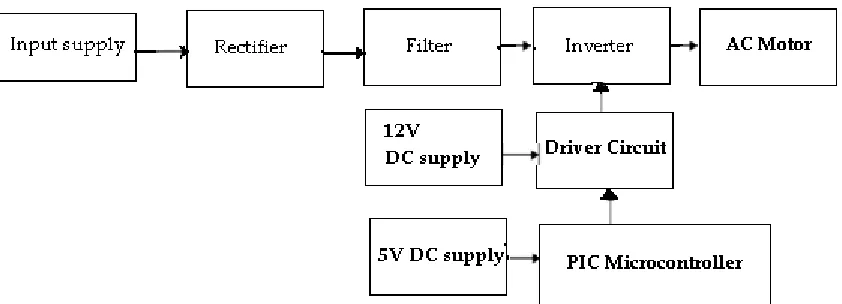
The block diagram of Low -Cost Direct Torque Control Algorithm for Induction Motor without AC Phase Current Sensors is shown in Fig. 1
Fig. 1 Block diagram of Low -Cost Direct Torque Control Algorithm for Induction Motor without AC Phase Current Sensors
In Fig.1 AC supply is the input supplied to the rectifier circuit. The rectifier circuit convert the AC supply to the DC supply and given to the filter circuit which filter the pulsating DC supply in to the smooth supply and supply the output to the inverter circuit. The inverter circuit consists of many switches it is drive by the driver circuit. The driver circuit has two functions one is to isolation and another for amplification. It can be used to amplify the 5V pulses to 12V for using transistor technology and provided isolation by using opto coupler. The pulse generator produces the pulses for the transistor by using PIC microcontroller. The PIC microcontroller produces a switching signal. The output of inverter is AC which is used to drive the Induction Motors. A low-cost single shunt current sensor induction motor (IM) DTC. The stator flux vector and the electromagnetic torque are directly calculated from the voltage and the current derived from a single dc -link voltage sensor (simple voltage divider) and a single dc -link current sensor (simple shunt resistor). The phase currents are estimated by two dc-link current measurement processes. This algorithm does not require additional computation burden or other motor parameter knowledge.
III. BASIC DTC OPERATION
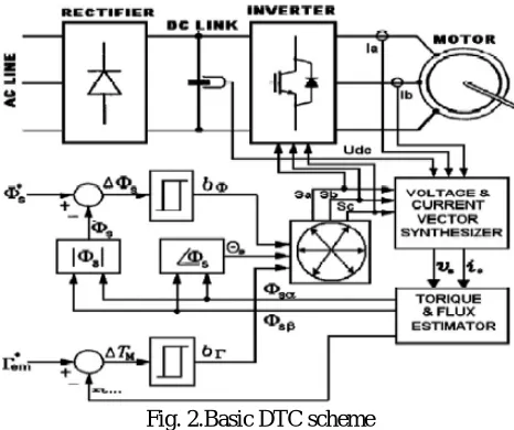
DTC uses a simple switching table to determine the most opportune inverter state to attain a desired output torque. By means of current and voltage measurements, it is possible to compute approximately the instantaneou s stator flux and output motor torque. The control algorithm based on flux and torque hysteresis controllers determines the voltage required to drive the flux and torque to the desired values within a fixed time period. The fundamental functional blocks used to implement the DTC scheme are represented in Fig.2.
Fig. 2.Basic DTC scheme
These equations only require the knowledge of the previously applied voltage vector Vs, measured stator current Is, stator resistance Rs, and the motor poles number p. Once the electromagnetic torque and stator flux magnitude are estimated, a hysteresis control is done and the voltage vectors to be applied are obtained from a switching table.
The stator voltage polar components (V s•, V s• ) on perpendicular (•,•) reference frame result from measured dc-link voltage Udc and the switching controls logical states Sa ,Sb, and Sc are given by
and stator current components (Ia, Ib)
The stator resistance can be assumed constant. During a switching period, the voltage vector applied to the motor is constant. By integrating the back electromotive force (EMF), the stator flux can be estimated using (5).
During the switching period, each voltage vector is constant and is then rewritten as
ISSN (Print) : 2320 – 3765 ISSN (Online): 2278 – 8875
I
nternational
J
ournal of
A
dvanced
R
esearch in
E
lectrical,
E
lectronics and
I
nstrumentation
E
ngineering
(An ISO 3297: 2007 Certified Organization)
Vol. 3, Issue 10, October 2014
A six equally spaced voltage vectors having the same amplitude and two zero voltage vectors are the only switching combinations, which can be chosen for an inverter operation. The selection of a voltage vector is made to preserve the torque and the stator flux inside the hysteresis bands limits.
IV. SINGLE CURRENT SENSOR DTC SCHEME
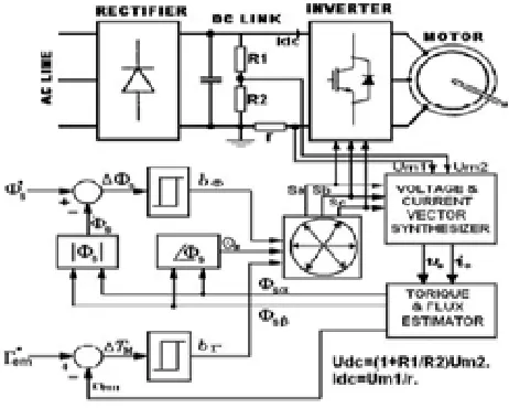
The basic DTC scheme (see Fig. 2) requires two current sensors at least. The proposed DTC scheme described in this paper uses only one shunt resistor for dc-link current measurement as revealed on Fig. 3. For this purpose, a suitable method to reconstruct the phase currents and voltages is devised with a simple modification of the basic DTC scheme using zone shift strategy. Two modifications of the basic DTC are used for estimating the three-phase currents from a single dc -link current sensor. On the first modification, the control system should be able to generate more voltage vectors.
This goal can be achieved approximately by applying, at each cycle period, different voltage vectors for prefixed time intervals, leading to a discrete space vector modulation (DSVM) technique. By using this modulation strategy, new voltage vectors can be synthesized with respect to those used in the basic DTC technique. It has been verified that subdividing the cycle period in two equal time intervals leads to a substantial reduction of current sensors without the need for too complex switching tables.
Fig. 3.Proposed DTC scheme
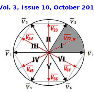
Using the DSVM technique with two equal time intervals, 12 new voltage vectors can be generated; we use only six active voltage vectors in our proposed DTC scheme as represented in Fig. 4.The red vectors represent the synthesized voltage vectors.
Fig 4 Proposed DTC sectors and inverter voltage sectors
Table I Proposed DTC Switching Table
V. SIMULATION RESULT AND DISCUSSION
MATLAB/SIMULINK model-based on power system toolbox was developed to examine the proposed control algorithm and the phase-current reconstruction feasibility
.
Fig. 5 Simulation Circuit of Low-Cost Direct Torque Control Algorithm for Induction Motor without AC Phase Current Sensors
ISSN (Print) : 2320 – 3765 ISSN (Online): 2278 – 8875
I
nternational
J
ournal of
A
dvanced
R
esearch in
E
lectrical,
E
lectronics and
I
nstrumentation
E
ngineering
(An ISO 3297: 2007 Certified Organization)
Vol. 3, Issue 10, October 2014
VI. INPUT & OUTPUT WAVEFORMS
The input voltage waveform for Low-Cost Direct Torque Control Algorithm for Induction Motor without AC Phase Current Sensors is AC voltage from supply is shown in Fig. 6.
Fig 6 The input voltage waveform
The Stator current waveform and rotor speed waveform is shown in Fig.7.
Fig 7. Stator current waveform and rotor speed waveform
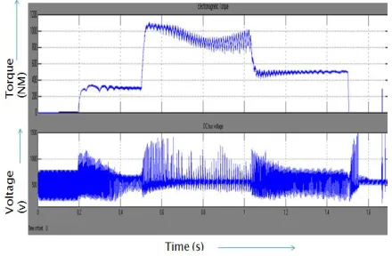
Fig 8. Electromagnetic torque and Dc Voltage waveform
VII. CONCLUSION
without changing the DTC strategy, a two-intervals discrete space vector modulation technique is used. The effectiveness of the proposed DTC algorithm using a single shunt resistor was verified by computer simulations and experimentally on a three-phase induction motor, rated at 1.1 kW.
REFERENCES
1. Takahashi and T. Noguchi, “A new quick-response and high-efficiency control strategy of an induction motor,” IEEE Trans. Ind. Appl
2. S. A. Zaid, O. A. Mahgoub, and K. El-Metwally, “Implementation of a new fast direct torque control algorithm for induction motor drives,”
IET Electr. Power Appl.
3. C. Patel, R. P. P. A. Day, A. Dey, R. Ramchand, K. K. Gopakumar, and M. P. Kazmierkowski, “Fast direct torque control of an open-end