ISSN 2286-4822 www.euacademic.org
Impact Factor: 3.4546 (UIF) DRJI Value: 5.9 (B+)
Design and Fabrication of Anti Reflection Coating
by Pulsed Laser Deposition
ALAA N. ABDUL GAFAAR Assistant Professor Department of Physics,College of Science for Women University of Baghdad, Iraq
KADHIM A. AADIM Assistant Professor Department of Physics, College of Science University of Baghdad, Iraq ZAINAB HAZIM ABDUL RAHEEM M. Sc. Student Department of Physics, College of Science for Women University of Baghdad, Iraq
Abstract:
In this work design and fabricated antireflection coating with single layer is discussed. The fabrication of antireflection coating is achieved using pulsed laser deposition technique (PLD) which deposits MgF2 as a thin film layer coating.
Result shows that wideband AR’C can fabricate when deposited thin film of MgF2 on glass at (1.2L) non-quarter optical
thickness in annealing temperature. Also result appears that we have overcome the problem of control of thickness layer coating using (PLD) technique.
Key words: Antireflection Coating, Pulsed Laser Deposition Technique
1. Introduction
the directions of light obey the laws of reflection and refraction, and their shape is adjusted to direct the light in a desired manner. So the other properties of the surfaces, such as reflectance, transmittance, or phase change, are rarely satisfactory.
The optical thin-film coating is technologically very important to modem optics [1]. Which have numerous
remarkable applications in many branches of science and technology, such as used in architecture, the automotive industry, energy conversion, computer and display devices, and communication energy [1]. One type of the most important
coating is an antireflection coating [2].
Antireflection coating deposited on the surface is one of the most important methods for reducing the reflection loss [3].
In some applications antireflection coatings are required not only reflection has reduced but also transmittance has increased considerably [4]. In this work we design and
fabrication AR’C with single layer by using PLD technique.
2. Basic theoretical
Designs AR’C depend on the Characteristic Matrix Theory to calculate reflection. To understand Characteristic Matrix Theory it is necessary to accept several statements. Where at the boundary the tangential of electric E and magnetic H components [5]
The characteristic matrix is:
( ) ( ⁄
) ( ) (2-1) When
=design wave length
Therefore, we can write the reflectance (R), as follow [5]:
( ) ( ) (2-2) To get minim reflection depending to equation (2-2) refractive index will be
√ (2- 3)
Where o and s are the refractive indices of the incident
medium and substrate, respectively.
The electromagnetic radiation with shipments does not cause any loss of energy interaction, causing the case of re-radiation, the article appears transparent to this radiation, but that did delay the re-radiation will reduce the speed actors to light, and thus it is said then that the material has a refractive index (n)
(2- 4)
The refractive index is a measure of polarizing material. Whenever it is great polarization delay is doing more and more the speed of light in a smaller article is the largest refractive index. [6]
The refractive index is associated with the reflectivity (R) and the Extinction coefficient (K) according to the following equation
n= {(1+R) 2/ (1-R) 2-(Ko2+1)} 1/2+ (1+R)/ (1-R) (2- 5)
The refractive index value can be calculated from the formula
[7]:
( ) ⁄ (2-6) The extinction coefficient K, which is related to the exponential decay of the wave as it passes through the medium, is defined
as [8,9]:
And related to the absorbance (A) reflectivity (R) and transmittance (T) as in the following relationship. [10]
A+ R+T= 1 (2- 7)
The design of a high quality AR coating is not an easy task to be done, since of the limitation in the optical materials diversity to be used in practice and the optimal thin film structure to be realized in order to obtain the lowest reflectivity. The optical AR coatings which designed in this work are valid for the spectral ranges 300-1100 nm [11]. This work design ARC
depends an analytical method for non quarter optical thickness.
3. Experimental part
For study and design ARC single layer with non quarter optical thickness of layer coating we compute reflection with aid of equation (2-2), as shown in figure (3.1).
Figure (3.1) demonstrate the optical performance of deign ARC with non quarter optical thickness of layer coating ,using MgF2 as material coating 1= 1.38, glass ( s) as
substrate and air ( o) incident medium the wavelength design
λο=632.8nm. While the construction parameters of this design
shows in table (3.1).
(a)
(c)
(d)
(e)
(f)
(g)
(h)
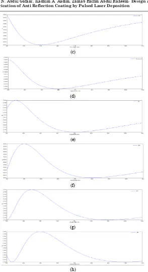
Figure (3.1) Design single layer ARC with non quarter optical thickness with
(d) Air/0.942 L/glass, (e) Air/1.11 L/glass, (f) Air/1.26 L/glass, (g) Air/1.41 L/glass, (h) Air/1.56 L/glass
Table (3.1) The construction parameters of design non quarter AR’C
Figure(4-2) Construction design Wave length of Minim reflection
(A) Air/0.476 L/glass 300 nm
(B) Air/0.636 L/glass 400 nm
(C) Air/0.788 L/glass 500 nm
(D) Air/0.942L/glass 600 nm
(E) Air/1.11 L/glass 700 nm
(F) Air/1.26 L/glass 800 nm
(G) Air/1.41 L/glass 900 nm
(H) Air/1.56 L/glass 1000 nm
Pulsed laser deposition (PLD) is a thin film deposition (specifically a physical vapor deposition, PVD) technique where a high-power pulsed laser beam is focused inside a vacuum chamber to strike a target of the material that is to be deposited. This material is vaporized from the target (in a plasma plume) which deposits it as a thin film on a substrate
[12].
The films are prepared in room temperature and annealing temperature of (523K) at the preparation condition using number of shots of (150,250,350,450) and energy laser pulse 500 mJ, Pulse width 10ns, Repetition frequency 6 Hz Rotating of target 3/min, Room temperature ,pressure
There is a problem to control thickness of layer coating in pulsed laser deposition technique.
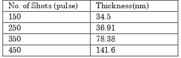
Figure (3.2) experiment relation between number of shoots and layer thickness
Table (3.2) number of shot and layer thickness No. of Shots (pulse) Thickness(nm)
150 34.5
250 36.91
350 78.38
450 141.6
The variation of the refractive index versus wavelength in the range 300–1100 nm, for different number of shots (150,250,350 and 450 shots) at R.T and annealing temperature (523 K), are shown in figures (3.3).
These figures view the dispersion phenomenon. The theoretical value of refractive index of MgF2 equal 1.38 but
cause of experimental conditions the value of the refractive index various with wavelength and become high stability over visible and near IR region have value in range (1.05-1.25) as appears in figure (3.3).
50 150 250 350 450 550
0 50 100 150 200
no
o
f
sh
o
t
-a-
-b-Figures (3.3): Refractive index as a function of wavelength for MgF2
films -a- at R.T and –b- annealing temperature of different thicknesses.
We can notice from these figures the relation between refractive index decreases at annealing temperature Ta and increase with thickness layer coating.
0.75 0.95 1.15 1.35 1.55 1.75 1.95 2.15
300 400 500 600 700 800 900 1000 1100
Refr acti ve Ind ex Wavelength (nm)
No.of shots = 150 puls No.of shots = 250 puls No.of shots = 350 puls No.of shots = 450 puls
0.75 0.95 1.15 1.35 1.55 1.75 1.95 2.15
300 400 500 600 700 800 900 1000 1100
Refr acti ve Ind ex Wavelength (nm)
No.of shots = 150 puls No.of shots = 250 puls No.of shots = 350 puls No.of shots = 450 puls
Alaa N. Abdul Gafaar, Kadhim A. Aadim, Zainab Hazim Abdul Raheem-Design and Fabrication of Anti Reflection Coating by Pulsed Laser Deposition
temperature at different thickness are shown in Figures (3.4 a and b). We can observe from these figures that extinction coefficient decreases with annealing temperature and with increasing thickness.
-a-
-b-Figures (3.4): Extinction coefficient as a function of wavelength for
MgF2 films -a- at R.T and –b- annealing temperature of different
thicknesses.
The optical performance of AR'C at RT show in Figure (3.5) which appears reflection increase with increase thickness of
0 0.1 0.2 0.3 0.4 0.5 0.6 0.7 0.8 0.9 1
300 400 500 600 700 800 900 1000 1100
Ex tinct io n Cof ficien t Wavelength (nm)
No.of shots = 150 puls No.of shots = 250 puls No.of shots = 350 puls No.of shots = 450 puls
0 0.05 0.1 0.15 0.2 0.25 0.3 0.35 0.4 0.45 0.5
300 400 500 600 700 800 900 1000 1100
Ext in ct ion C offic ie n t Wavelength (nm)
No.of shots = 150 puls No.of shots = 250 puls No.of shots = 350 puls No.of shots = 450 puls
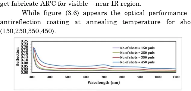
layer coating and the samples of number shots (150,250,350) get fabricate AR'C for visible – near IR region.
While figure (3.6) appears the optical performance of antireflection coating at annealing temperature for shots (150,250,350,450).
Figure (3.5) optical performance of AR'C for experiment result at R.T for different thicknesses.
At (Ta) the reflection decrease corresponding to RT and increase
with increase thickness of layer coating .Also in annealing temperature we get fabricate AR'C in the visible - near IR region for shots (150,250,350,450).
Figure (3.5) and (3.6) appear fabricate wide band AR'C.
Figure (3.6) optical performance of AR'C for experiment result at Ta
for different thicknesses
4. Conclusions
This work fabricates wide band antireflection over visible-near IR region. Result shows that non quarter of MgF2 as thin film
Experimentally conclude when increase number of shots, the geometric thickness will be increase. Also the extinction coefficient and refractive index are decrease by annealing of MgF2 film.
REFERENCES
[1] Jinn, M.Y and Cheng, Y.K. 2000.”A Robust Evolutionary Algorithm For Optical Thin-Film Designs”.Ieee,2:978-985. [2] Mit Researchers Create A 2007 . “Perfect Mirror”. Mit Press Release. 1998-11-26. Retrieved -01-17.
[3]Sun Xiu-Ju, Li Hai-Ling, Li Xu-Dong, Ren Bing-Yan, Zhou Chun-Lan, Zhao Lei, Wang Wen-Jing. 2009. “Preparation and Characterization Of Mgf2/Zns Double-Layer Antireflection Films Applied In Silicon Solar Cells”. Journal of Synthetic Crystals. 38(3):547-551.
[4] Asghar,M.H., Khan,M.B. and Naseem, S. 2003.”Modeling High Performance Multilayer Antireflection Coatings for Visible and Infrared (35µm) Substrates”. V. Lashkaryov Institute Of Semiconductor Physics, National Academy Of Sciences Of Ukraine,6(4): 508-513.
[5] Macleod, H. A., 1986. “Thin-Film Optical Filters” (Mcgraw-Hill, New York).
[6] S. O. Kasap, 2002.“Principles of Electronic Materials and Devices”,2nd Ed, McGraw-Hill, New York.
[7] Park, M. C., Yoon, W. H., Lee, D. H., Myoung, J. M., Bae, S. H., Lee, S. Y. and Yun, I., 2002."Effect Of Misfit Strain On Properties Of Tio2 Films Grown By Pulsed Laser Deposition, "Mat. Res. Soc. Symp. Proc.696, 25.
[8] Grall, S.,” Fundamentals of Optics” (Mcgraw-Hill, New York, 2001).
[9] Sakaguchi, F., and Kobayashi, T., 2010. ”PhysicsAnd Application Of Tio2 For Gas Sensing Material, J. Apply. Phys
[10] Moldonado, A., Asamoza, R., Ortegaj, C. and Hernandez, R., 1999. J. Solar Energy Mater. Sol. cells, 57(4):331
[11] Honciuc, Gh., Singurel Gh., and Timus C.