ISSN (Print) : 2320 – 3765 ISSN (Online): 2278 – 8875
I
nternational
J
ournal of
A
dvanced
R
esearch in
E
lectrical,
E
lectronics and
I
nstrumentation
E
ngineering
(An ISO 3297: 2007 Certified Organization)
Vol. 4, Issue 4, April 2015
Digital MPPT Interface for PV Module
Rehan Ahmed
M.Tech. Student (Elect. Power System), Al-Falah School of Engineering and Technology, Faridabad, Haryana,
India
ABSTRACT: A photovoltaic module is an array of photo voltaic cell when this module expose to solar irradiance, it
yields electrical energy in the form of direct current. The source impedance of PV Module functionally follows module surface temperature and intensity of solar irradiance, varies with the position of sun that is ever changing due to tilt in the earth and its elliptical orbit. The maximum energy transfer to load from this PV module is only when load impedance attuned to Maximum Power Point (MPP) in I v/s V characteristic curve of the PV module. An interface needs between load (Solar-Invertor) and PV module. This Maximum Energy Transfer (MET) interface is in the form of Switch Pass regulator, conceive and control vide digital processor. The energy yield is highly efficient and smooth. It is low cost interface suitable for domestic and industrial use from low to higher end in the spectrum of utilisation.
KEYWORDS: Solar irradiance, Temperature effect, MET, Maximum Energy Transfer, PV Module, Digital Interface,
Switch Pass Regulator, MPPT
I. INTRODUCTION
The function of a Photo Voltaic cell derives on the principle of photoelectric1 effect, its phenomenon in which an electron ejects from the conduction band because of solar irradiation absorption which have specific wavelength, from the specimen matter i.e. solids, liquids or gases. In a photovoltaic cell, sunlight strikes the surface of semiconductor material some portion of the incident solar energy absorbs in the semiconductor material and rest reflects or disperse. The electron from valence band jumps to the conduction band only when absorb energy supersedes band gap energy in this material. The pairs of hole-electrons create in the illuminated region of this material and are now free to move from conduction band. These free electrons force to travel in predetermine direction by the action of electric field presents in the PV cells. These free and flowing electrons attribute to current and presence of electric field attribute to voltage and the electric energy thus creates can be utilise through metallic connections from the top and bottom of PV cell. An array of these cells makes a PV module.
Sunlight leads the way: All renewable energies derive in one form or anotherfrom the sun. The sun itself has enormous potential tobecome the most dominant direct source of all renewableenergies. It provides, within three days into earth„satmosphere, as much energy as that contained by all ofthe known fossil fuel reserves underground. It has beena source of renewable energy for millions of years andnow looks set to play a leading role in providing energy tosociety for the near future.World‟s fastest growing energy technologyPhotovoltaic (PV) modules are the main source for capturingthe sun‟s energy and as such PV power systems, with theircarbon dioxide-free, limitless, safe and quiet power, experiences the highest growth rate of any energy producingtechnology. With today‟s advanced technologies, the actualenvironmental impact of a PV power system restores after only a few years of operation. Finally, PV power systemsimprove the security of the transmission network supplythrough a modular and decentralized power generationconcept.
ISSN (Print) : 2320 – 3765 ISSN (Online): 2278 – 8875
I
nternational
J
ournal of
A
dvanced
R
esearch in
E
lectrical,
E
lectronics and
I
nstrumentation
E
ngineering
(An ISO 3297: 2007 Certified Organization)
Vol. 4, Issue 4, April 2015
II. SURVEY OF CONTEMPORARY LITEARTURE
Safari A., Mekhilef S.2 presented a paper about that thebasic structural unit of a solar module is the PV cells and PV module characteristics comprehensively discuss which indicates an exponential and non-linear relation betweenoutput current and voltage of PV module. It gives an idea about the significant points on each I-V curve: open circuit voltage, short circuit current and the operating point where themodule performs the maximum power (MPP).
Roberto Faranda and Sonia Leva3 discussed manyMPPT techniques under the energy production point of view: Constant Voltage Method, Short-Current Pulse Method, Open Voltage Method, Perturb and Observe Method, Incremental Conductance Method and Temperature Method.These techniques vary amongthem in many aspects, including simplicity, convergence speed, hardware implementation, sensors required, cost, range of effectiveness and need for parameterization.
N.Femi, G.Petrone, G.Spagnuolo andM.Vitelli4 discussedhow the Maximum power point tracking (MPPT) techniques are used in photovoltaic (PV) systems to maximize the PV array output power by tracking continuously the maximum power point (MPP) which depends on panels temperature and irradiance conditions. The issue of MPPT hasaddressed in different ways in the paper.
E. Durán, M. Sidrach-de-Cardona, J. Galán, and J.M. Andújar5discussed several topologies of DC-DC converters formeasuring the characteristic curves of photovoltaic (PV)modules is theoretically analysed. Eight topologies of DC-DC converters with step-down/step-up conversion relation Buck-Boost single inductor, CSC (Canonical Switching Cell), CUK, SEPIC (Single-Ended Primary Inductance Converter), Zeta, Fly back, Boost-Cascaded, and Buck-Boost-Cascaded Converters) are compared and evaluated.
III. BASICS OF SINGLE SOLAR CELL
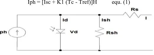
Thestudy of single diode solar cell model, as shown in the figure 1 offers a good compromise between simplicity and accuracy. The basic structure consists of a current source and a parallel diode, whereby Iph represents the cell photocurrent while Rsh and Rs are respectively, the intrinsic shunt and series resistances of the cell.
In the following equations (equ. 1) of a PV cell the photocurrent, Iph depends linearly on the solar irradiation and the temperature.
Iph = [Isc + K1 (Tc - Tref)]H equ. (1)
Fig 1 Schematic diagram of single diode solar cell equivalent circuit
Whereas, Iph is the nominal generated current at 25˚C and 1kW/m2; Isc is the cells short-circuit current at a 25˚C and 1kW/m2,
K1 is the cells short-circuit current temperature coefficient (0.0017A/K), Tref is the cell‟s reference temperature, and H is the solar insolation in kW/m2.
IV. MAXIMUM POWER POINT (MPP)
ISSN (Print) : 2320 – 3765 ISSN (Online): 2278 – 8875
I
nternational
J
ournal of
A
dvanced
R
esearch in
E
lectrical,
E
lectronics and
I
nstrumentation
E
ngineering
(An ISO 3297: 2007 Certified Organization)
Vol. 4, Issue 4, April 2015
their operating environment. The fill factor, abbreviate „FF‟, is a parameter that characterizes the non-linear electrical behaviour of the solar cell. Fill factor is define as the ratio of the maximum power Pmax from the solar cell to the product
of Open Circuit Voltage Voc and Isc Short-Circuit Current. FF = 𝑃𝑚𝑎𝑥
𝑉𝑜𝑐 𝑥 𝐼𝑠𝑐 or Pmax= ff x Voc x Isc (Equ 2.)
The unique operational conditions have a single operating point for PV Cells with the maximum Voltage and Current. Although for the majority of its useful curve, it acts as a constant current source. Moreover, the power delivers to a
device is optimize where the derivative 𝑑𝑃
𝑑𝑉= 0 , in addition I and V has finite value. This is the MAXIMUMPOWER
POINT(MPP). The efficiency of a PV module is between 16 -18%. Hence, any change in the operating condition needs simultaneous change in MPP to maintain efficiency, this track of MPP necessities the use ofMPP Trackers. There are around nineteen technologies available for design of MPPT.
Fig 2
V. MAXIMUM POWER POINT TRACKING TECHNOLOGY
In the present context, the genesis of MPPT Technology derives on Bisection Search Theorem (BST). This theorem is one of the bracketing methods for finding roots of the equations. Assume that function y= f(x) and an interval [a, b] which contains a root x* in f(x) that lies somewhere in the interval such that f(c) = 0. The BST systematically moves the ends of the interval closer and closer together in the pace of halving interval for each step until an interval of the arbitrarily small width that brackets the Zero obtains.
The decision step for this process is to first choose the midpoint c = (𝑎+𝑏)
2 and then analyse the three possibilities that
might rise. If f (a) and f (b) have opposite signs, a zero lies in [a, c]. If f (a) and f (b) have opposite signs, a zero lies in [c, b]. If f (c) =0, then the zero is c. If either case (1) or (2) occurs, an interval half as wide as the original interval that contains the root.
The figure 3 is curve f(x) V/S x, whereas, x=a and x=b are two arbitrary point on the curve and x=c is mid-section point,
and the maxima lies between c & b i.e. 𝑑𝑓 (𝑥)
ISSN (Print) : 2320 – 3765 ISSN (Online): 2278 – 8875
I
nternational
J
ournal of
A
dvanced
R
esearch in
E
lectrical,
E
lectronics and
I
nstrumentation
E
ngineering
(An ISO 3297: 2007 Certified Organization)
Vol. 4, Issue 4, April 2015
VI. MAXIMUM POWER POINT TRACKING USING BISECTION THEOREM
The application of BST in the MPPT technique in PV systems, the function of y= f(x) and the variable x should be chosen carefully. Figure 4 shows a power-voltage (P -V) curve. From the (P -V) curve, it can be observe that the change in power with respect to voltage approaches zero at the maximum power point. Obviously, the powers at short circuit voltage (0 V) and open circuit voltage (Voc ) are zero, so maximum power should not be happen in these two particular points, even though the changes in the power at these two points are also zero, which is caused by the small powers around these two points. Thus, tracking the maximum power point is essential to find the root in the function dp by regulating the voltage of solar module or solar array. As a result, the function y= f(x) can be regarded as the change in power dp, where the variable x is the voltage of solar module or solar array.Fig 4. Power-Voltage (P -V) curve
VII. DESIGN OF MPPT INTERFACE
This interface is built on AT89C2051 is a low-voltage, high-performance CMOS 8-bit microcomputer with 2K bytes of Flash programmable and erasable read-only memory (PEROM). This device has high-density non-volatile memory technology and is compatible with the industry-standard MCS-51 instruction set. The combination of versatile 8-bit CPU with Flash on a monolithic chip, the Atmel AT89C2051 is a powerful microcomputer that provides a highly flexible and cost-effective solution to MPPT in solar PV application. The AT89C2051 provides the following standard features: 2K bytes of Flash, 128 bytes of RAM, 15 I/O lines, two 16-bit timer/counters, a five vectors two-levels interrupt architecture, a full duplex serial port, a precision Analog comparator, on-chip oscillator and clock circuitry. The output Volt and Current are sample using shunt resistor. These parameters are multiplex and convert to 8-bit stream using Analog to Digital Convertor ADC808.
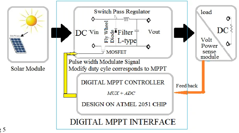
VIII. THE LAYOUT OF PHOTOVOLTAIC SYSTEM WITH MAXIMUM POWER POINT TRACKER
INTERFACE
ISSN (Print) : 2320 – 3765 ISSN (Online): 2278 – 8875
I
nternational
J
ournal of
A
dvanced
R
esearch in
E
lectrical,
E
lectronics and
I
nstrumentation
E
ngineering
(An ISO 3297: 2007 Certified Organization)
Vol. 4, Issue 4, April 2015
ripples. The duty cycle of Pass Transistor manages by Pulse Width Modulation signal from 2051 to control load current, hence load impedance with reference to MPP. The power feedback signal derives by formula Pload= VLxIL Equ. 3
Fig 5
The operating frequency of Switch Mode Pass Regulator is 250 Khz.
The DC Load Voltage is measured using Potential divider network to bring Vmax, within limit of 5 Volt.
The DC Load current measures using a 75-millivolt Shunt, whereas 75 mV corresponds to maximum Load current.The maximum Power output is measured Pmax =VL x IL within algorithmic embedded in 2051. The Pass Transistor direct drive is through a base resistance of few hundred ohms.
IX. SIMULATION RESULT
a) Measuring Current yield at constant Voltage and varying Solar Irradiation:
The simulation results are clear in their interpretation the depletion of Irradiance still yields more energy with MPPT Interface. While without MPPT current remains constant. The figure 6 is a plot Current v/s Time with different Irradiation.
ISSN (Print) : 2320 – 3765 ISSN (Online): 2278 – 8875
I
nternational
J
ournal of
A
dvanced
R
esearch in
E
lectrical,
E
lectronics and
I
nstrumentation
E
ngineering
(An ISO 3297: 2007 Certified Organization)
Vol. 4, Issue 4, April 2015
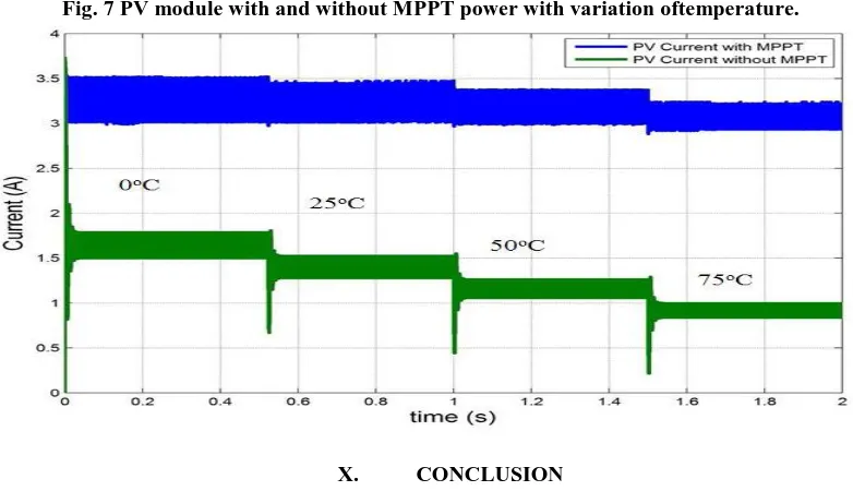
b) Measuring Current yield at constant Voltage and varying PV Module Temperature:
The simulation results are clear in their interpretation increase in the temperature still yields more energy with MPPT Interface, current remains constant. While without MPPT current depletes and yield falls. The figure 7 is a plot Current v/s Time with different Irradiation.
Fig. 7 PV module with and without MPPT power with variation oftemperature.
X. CONCLUSION
The interface is very fast in a tunning to MPP as in Bisection Search Technology the algorathmic has to seek only half of curve in each cycle, so it can establish MPP within a very few cycles in the comparison to other technologies. The series component is only MOSFET or IGBT the loss in this device is very low due to small ON resistance. The Inductor in the series is loss less because it has few turn and wound on the ferrite material, due to high switching frequency, as it is only utilse to smooth harmonics in the output DC Power. The direct current doesn‟t have magnetizing or Tan δ Loss. The energy absorbs in each cycle in the form of magnetizing current is feed back to load during off cycle using Flywheel action of the diode. Hence, the efficiency of this topology is very high and cost very low due to few components.
REFERENCES
1. H. J. M¨oller, “Semiconductors for Solar Cells”. Norwood, MA: Artech House, 1993
2. Safari A, Mekhilef S, “Simulation and Hardware Implementation of Incremental Conductance MPPT with Direct Control Method Using Cuk
Converter”, IEEE Trans, March 2010.
3. Roberto Faranda, Sonia Leva, Comparison of photovoltaic array maximum power point tracking techniques,”
4. IEEE Trans. Energy Conversion, Vol. 22, No. 2, June 2007, pp. 439–449
5. N.Femia, D.Granozio, G.Petrone, G.Spaguuolo, M.Vitelli, “Optimized One-Cycle Control in Photovoltaic Grid Connected Applications”, IEEE
Trans. Aerosp.Electron.Syst, vol. 2, no 3, July 2006.
6. “Maximum Power Point Tracking: an Algorithm for Rapidly Chancing Atmospheric Conditions”, IEE Proc.-Gener.Transm.Distrib., vol. 142,