Available online:
https://edupediapublications.org/journals/index.php/IJR/
P a g e | 2088Optimisation of Process Plan for Support Component of a
Dynamic Air Frame in a Missile by Designing a Fixture
1
Thota Anil,
2s. Mohan Kumar,
3G Srikanth Reddy
1
M.Tech student,
2Assistant professor,
3Assistant professor. Department of Mechanical
Engineering, Avn Institute of Engineering and Technology, Hyd, T.S
ABSTRACT
A missile is a self-propelled guided weapon system. There are five system components in missiles. They are:
1. Targeting and/or guidance 2. flight system
3. engine 4. air frame 5. Warhead.
Bulk Head of missile was holded by a thin walled component called support head bulk. Machining is to be done inside and outside of the component. To machine the component a fixture is required. The fixture should be special to hold the component rigidly during machining. The component is clamped at top for CNC machining. The component should have dimensional accuracy. To get dimensional accuracy, 4-axis turning machine is used to develop the component. By using 4-axis turning machine, the cost and work of the labour is reduced.
This project is aimed to predict the stable speed range for machining thin-ribbed bulk head support structure with minimum deflection and high surface finish. This project is aimed at optimizing the manufacturing process of the support bulk head. Two different process plans along with NC programs shall be developed to decrease number of setups, which reduces machining time and the unit cost of the component. The 3D model of Support bulk head shall be modeled in NX-CAD. NX-CAM software shall be used to generate the NC program of Support bulk head.
INTRODUCTION
Bulk Head of missile was holded by a thin walled component called support head bulk. Machining is to be done inside and outside of the component. To machine the component a fixture is required. The fixture should be special to hold the
component rigidly during machining. The
component is clamped at top for CNC machining.
The component should have dimensional accuracy. To get dimensional accuracy, 4-axis turning machine is used to develop the component. By using 4-axis turning machine, the cost and work of the labour is reduced.
High speed machining is one of the emerging cutting processes having tremendous potential compared to conventional machining processes. It is an economically viable alternative to other forms of manufacturing such as forming, casting, and sheet metal build-up. Additionally, high-speed milling processes can produce more accurate and repeatable results, as well as reduce the costs associated with assembly and fixture storage, by allowing several components to be combined into a monolithic machined part. Important applications of high-speed milling include the manufacture of dies and molds, numerous steel and aluminum parts for automobiles, and thin-walled, aluminum components for aircraft.
3D MODELING OF SUPPORT COMPONENT Bulk head support 2D Drawing
A 2D drawing is used to design a 3D model for our component using Unigraphics NX 7.5 CAD software.
Below shows the 2D drawings of the
Available online:
https://edupediapublications.org/journals/index.php/IJR/
P a g e | 2089Below shows the revolve of 2D sketch of support
Below shows the holes on support part
Below shows the holes on side of support
Below shows the circular array of side hole
Available online:
https://edupediapublications.org/journals/index.php/IJR/
P a g e | 2090Below shows the extrude of slot
Below shows the circular array of slot
COMPUTER AIDED MANUFACTURING Maintaining this stable speed bulk head support component is manufactured on CNC machine.
Methodology used in manufacturing of support is mentioned below:
Identifying suitable machine.
Selecting suitable tools for manufacturing
thin walled component.
Listing down the Sequence of operations
performed on missile piston.
Generating tool path at specified cutting
speed.
Generating NC program using NX-CAM
software.
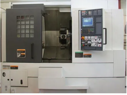
Identify suitable machine: CNC MACHINE USED IN THIS PROJECT
MORI SEIKI 4-AXIS CNC turning machine is used for machining support. MORI SEIKI offers the industry's best lineup of high-performance lathes with better precision and rigidity, greater multi-axis compatibility and smaller footprints.
High rigidity with Integrated Turning Spindle. Spindle is directly coupled with motor. Rigid Turret with BIM (Built In Motor) Technology. Directly coupled Integrated driven tools. Is a patent technology. Y-axis machining, Up to 100mm (+/- 50). 4-axes simultaneous machining, C-axis with 360 deg and Y-axis, Machine accuracies, Positional Accuracy +/- 0.005mm, Repeatability +/- 0.003mm. In 4-axis turning machine, Axis represents as work piece rotation and spindle movement in x, y, z directions.
Fig shows 4-axis CNC MORI SIEKI turning machine Selection of tools:
Selection of tools plays an important role in manufacturing any component. Proper tools must be
selected otherwise in manufacturing process
improper tools results in damage of work piece or damage to the tools, tool holders. Suitable tools for manufacturing support are listed below
Available online:
https://edupediapublications.org/journals/index.php/IJR/
P a g e | 2091OD_80_L rough
OD_55_L finish
ID_80_L rough
ID_55_L finish
Sequence of operations performed on support component:
Sequence of operations performed on support in NX-CAM software are listed below TURNING OPERATIONS
Facing
Rough_Turn_OD
Rough_Back_Turn
Finish_Turn_OD
Groove_OD
Rough_Bore_ID
Groove_Face
MILLING OPERATIONS
Drilling
Planar Mill
Manufacturing process planning using Turning, Vertical Mill.
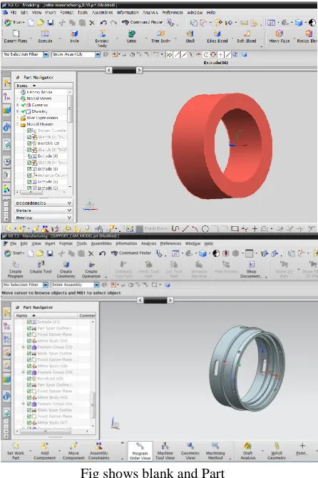
Turning operations:
Below image shows the blank and part of support
Fig shows blank and Part
Below image shows the spun generated for turning operation
Fig shows spun of support
Available online:
https://edupediapublications.org/journals/index.php/IJR/
P a g e | 2092Below image shows the facing operation on bulk
head support maintaining speed at 1500rpm and feed 0.25 mmpr.
Below image shows the facing operation verification
Below image shows the Rough turn OD operation on bulk head support maintaining speed at 1500rpm and feed 0.25 mmpr.
Below image shows the Rough turn OD tool path verification
Below image shows the Rough back turn OD operation on bulk head support maintaining speed at 1500rpm and feed 0.25 mmpr.
Below image shows the Rough back turn OD tool path verification
Available online:
https://edupediapublications.org/journals/index.php/IJR/
P a g e | 2093Below image shows the Rough Bore ID tool path
verification
Below image shows the Groove face operation on bulk head support maintaining speed at 1500rpm and feed 0.25 mmpr.
Below image shows the Groove face tool path verification
Set up_2 in turning operation: Part & blank:
This IPW will be the blank for setup_2. After setup_1 operations this component is loaded reversely on the turning machine operations.
Available online:
https://edupediapublications.org/journals/index.php/IJR/
P a g e | 2094Below image shows the facing operation verification
Below image shows the Rough turn OD operation on bulk head support maintaining speed at 1500rpm and feed 0.25 mmpr.
Below image shows the Rough turn OD tool path verification
Below image shows the Rough Bore ID operation on bulk head support maintaining speed at 1500rpm and feed 0.25 mmpr.
Below image shows the Rough Bore ID tool path verification
Available online:
https://edupediapublications.org/journals/index.php/IJR/
P a g e | 2095Below image shows the Groove face operation on
bulk head support maintaining speed at 1500rpm and feed 0.25 mmpr.
Milling operation
This IPW will be the blank for milling operation. After setup_2 operations this component is loaded on the milling machine.
Below image shows the Planar mill operation on bulk head support maintaining speed at 1600rpm and feed 250 mmpm.
Below image shows the planar mill tool path verification
Below image shows the Drilling operation on bulk head support maintaining speed at 1500rpm and feed 0.25 mmpr.
Available online:
https://edupediapublications.org/journals/index.php/IJR/
P a g e | 2096Manufacturing process of bulk head support on CNC
machine:
Raw material is placed on the machine, and
degree of freedom is arrested using fixtures.
The raw material is loaded on the turning
machine. Internal operations are done first because bulk head support component is thin walled with dimensions 0.8 to 7mm thickness.
After completing internal operations
external operations are done
After completing turning operations the
semi finished component is loaded on the milling machine for drilling operations. The component is damaged when external operations are performed on machine because the component became hallow after completing internal operations. To avoid damage there should be support from internal when external operations are performed. Irregularities in the surface may form nucleation sites for cracks or corrosion. In order to avoid this rejection problem mandrel is designed.
DESIGN OF MANDREL
Mandrel is modeled by considering inner dimensions of Bulk head support. Inner dimensions of Bulk head support will be outer dimensions of mandrel.
2D Drawing for Mandrel
Below image shows sketch of mandrel
Below image shows revolve of the mandrel
Tool path generation of mandrel:
Below image shows facing operation of mandrel
Available online:
https://edupediapublications.org/journals/index.php/IJR/
P a g e | 2097Below image shows verification of Rough Turn_OD
operation of mandrel
Below image shows Rough Back Turn operation of mandrel
Below image shows verification of Rough Back Turn operation of mandrel
Below image shows verification of Groove face operation of mandrel
Bulk head support is again machined by using mandrel. After completing internal operation mandrel is used as jig. Mandrel makes contact inside the Bulk head component and this contact supports the component at high cutting speeds and gives high surface finish. The cutting speed preferred to get high surface finish is between 600-3300 rpm which is obtained from analysis report.
MANUFACTURING PROCESS OF SUPPORT ON CNC MACHINE.
Available online:
https://edupediapublications.org/journals/index.php/IJR/
P a g e | 2098Manufacturing process planning using Turning-mill
machine
Raw material is placed on the machine, and
degree of freedom is arrested using fixtures.
The raw material is loaded on the turn-mill
machine. ID & OD operations and grooving operations are done as well as milling operations also done on the raw material because it is 4-axis turn-mill machine and it is capable to do milling operations and drilling operations.
The time taken by piston component for manufacture on tuning-mill machines is 19m 32sec.
Below image shows manufacturing time of support component
Graphical representations of surface roughness and feed at different speeds
Iterations are made to obtain high surface finish at varying speeds.
ITERATION 1
Surface roughness obtained at constant speed 700rpm. The values are plotted graphically.
SURFACE ROUGHNESS VS FEED
Under ideal conditions of
machining at constant speed 700rpm, as the feed is increased from 0.1 to 0.45mm/rev surface roughness decreased slowly from 0.65 to 0.5(at f=0.25mm/rev) and then it increased.
ITERATION 2
Surface roughness obtained at constant speed 800rpm. The values are plotted graphically
SURFACE ROUGHNESS VS FEED
Under ideal conditions of
machining at constant speed 800rpm, as the feed is increased from 0.1 to 0.45mm/rev surface roughness decreased slowly from 0.8 to 0.6(at f=0.3mm/rev) and then it increased.
ITERATION 3
Surface roughness obtained at constant speed 1300rpm. The values are plotted graphically SURFACE ROUGHNESS VS FEED
0 0.2 0.4 0.6 0.8 1
0.1 0.15 0.2 0.25 0.3 0.35 0.4 0.45
su rfac e r o u gh n e ss feed mm/rev surface rough… 0 0.2 0.4 0.6 0.8 1
0.1 0.15 0.2 0.25 0.3 0.35 0.4 0.45
Available online:
https://edupediapublications.org/journals/index.php/IJR/
P a g e | 2099Under ideal conditions of
machining at constant speed 1300rpm, as the feed is increased from 0.1 to 0.45mm/rev surface roughness decreased slowly from 0.9 to 0.63(at f=0.25mm/rev) and then it increased.
ITERATION 4
Surface roughness obtained at constant speed 1500rpm. The values are plotted
graphically
SURFACE ROUGHNESS VS FEED
Graphical representation of surface roughness Vs feed
Fig shows Graph of feed and surface roughness
Under ideal conditions of
machining at constant speed 1500rpm, as the feed is increased from 0.1 to 0.45mm/rev surface roughness decreased slowly from 0.8 to 0.4(at f=0.25mm/rev) and then it increased.
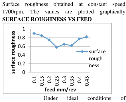
ITERATION 5
Under ideal conditions of
machining at constant speed 1700rpm, as the feed is increased from 0.1 to 0.45mm/rev surface roughness decreased slowly from 0.9 to 0.57(at f=0.25mm/rev) and then it increased.
Hence the feed is optimized at 0.25mm/rev with minimum surface roughness no. 4. It is concluded that at feed 0.25mmpr and speed 1500 rpm we get high surface finish.
MANUFACTURING OF THE COMPONENT (support) ON MORISEIKI TURN MILL: Raw material:
Fig shows raw material for support component After Turing & drilling operations:
Final component
0 0.2 0.4 0.6
0.1 0.2 0.3 0.4
su rface r o u gh n feed mm/rev surface rough ness 0 0.2 0.4 0.6 0.8 1
0.1 0.15 0.2 0.25 0.3 0.35 0.4 0.45
su rface r o u gh n e ss feed mm/rev surface rough ness 0 0.2 0.4 0.6 0.8 1
0.1 0.15 0.2 0.25 0.3 0.35 0.4 0.45
Available online:
https://edupediapublications.org/journals/index.php/IJR/
P a g e | 2100Fig. final component
RESULTS AND DISCUSSION Rejection and Reworks of bulk head support
Fig shows Graph of rejection and reworks rate without mandrel
Fig shows Graph of rejection and reworks rate using mandrel
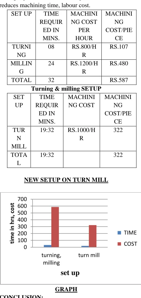
Graphical representation of rejection and reworks rate of bulk head support shows less rejection and reworks rate when manufactured by using mandrel which will arrest total degree of freedom and supports from internal and allows high
cutting speed and increases production rate and reduces machining time, labour cost.
SET UP TIME
REQUIR ED IN MINS. MACHINI NG COST PER HOUR MACHINI NG COST/PIE CE TURNI NG
08 RS.800/H
R
RS.107
MILLIN G
24 RS.1200/H
R
RS.480
TOTAL 32 RS.587
Turning & milling SETUP SET UP TIME REQUIR ED IN MINS. MACHINI NG COST MACHINI NG COST/PIE CE TUR N MILL
19:32 RS.1000/H
R
322
TOTA L
19:32 322
NEW SETUP ON TURN MILL
GRAPH CONCLUSION:
1) bulk head support is modeled using
Unigraphics software NX_CAD
2) Mandrel is designed to support the
component from internal and to reduce the rejection rate.
3) NC program is generated using
Unigraphics software NX_CAM
0 5 10 15
150 250 350 450 550
n o .o f p ar ts r ejec ted in %
no.of parts inspected
Batch production with
out mandrel
Rejection and Reworks 0 2 4 6 15 0 25 0 35 0 45 0 55 0 no.of par ts r ej ect ed i n %no.of parts inspected
Available online:
https://edupediapublications.org/journals/index.php/IJR/
P a g e | 21015) Graphical representation of feed and
surface roughness is plotted with varying
inputs. The feed is optimized at
0.25mm/rev with minimum surface
roughness 0.4. It is concluded that at feed 0.25mmpr and speed 1500 rpm we get high surface finish.
6) Graphical representation of time and cost is
shown in results along rejection and reworks rate.
7) The total time required for the
manufacturing of the component is reduced.
8) The production cost of the product is also
reduced.
REFERENCE:
[1] Z.-C. Lin and J.-S. Chang, “The building of
spindle thermal displacement model of high speed machine center”, Int. J. Adv.Manuf. Technol., vol. 34, pp. 556-566, Sept. 2007.
[2] E. Abele, Y. Altintas, and C. Brecher, “Machine
tool spindleunits”, CIRP Annals – Manuf. Technol., vol. 59, pp. 781-802, 2010.
[3] C. Li, Y. Ding, and B. Lu, “Development and
Key Technology inHigh Speed Cutting”, J. Qingdao Technol. Univ., vol. 30, pp. 7-16,Feb. 2009.
[4] Z.-C. Lin, and J.-S. Chang, “The building of
spindle thermal displacement model of high speed machine center”, Int. J. Adv. Manuf. Technol., vol. 34, pp. 556-566, Sept. 2007.
[5] E. Abele, Y. Altintas, and C. Brecher, “Machine
tool spindle units”, CIRP Annals – Manuf. Technol., vol. 59, pp. 781-802, 2010.
[6] C. Li, Y. Ding, and B. Lu, “Development and