Volume 8, No. 4, May 2017 (Special Issue)
International Journal of Advanced Research in Computer Science
RESEARCH PAPER
Available Online at www.ijarcs.info
Implementation of Photovoltaic Module as an Input Source in development of Full
Bridge Converter
Neha Bhagat
Phd(EE).Astt. Professor &Head (EE) Jalandhar , Punjab, India [email protected]
Abstract: An electrolyzer is part of a renewable energy systemand produces hydrogen from water electrolysis that is utilizedin fuel cells. A dc-to-dc converter is essential to couple the electrolyzerto the system dc bus. This paper presents development & implementation of full bridge converter in Renewable Energy System application using PV module is designed and simulation results are presented.
Keywords: DC-to-DC converters, electrolyzer, renewable energy system (RES), resonant converters.
1. INTRODUCTION
[image:1.595.41.275.492.651.2]Renewable energy is generally defined as energy that comes from resources which are naturally replenished on a human timescale such as transforms the energy found in sunlight, wind, falling water, waves, geothermal heat, or biomass into a useable form, such as heat or Electricity. Renewable energy storage in the form of hydrogen may overcome the inherent weakness of battery-basedenergy storage methods like physical size, inadequatelife span, and initial capital cost of the battery bank coupled with transportation, maintenance, and battery disposal issues. [1].
Fig 1. Block diagram of typical RES system[5]
At the times when the renewable resources exceed the load demand, hydrogen would be produced and deposited through water electrolysis. For this purpose, electrolyzer that breaks water into hydrogen and oxygen is used as an essential part of RES in Fig. 1. At the times when the load demand exceeds the renewable resource input, a fuel cell operating on the stored hydrogen would deliver the balance of power. To ensure proper flow of power between the
system elements, the existing energy from different sources is coupled to a low voltage dc bus. A direct connection of dc bus to the electrolyzer is not appropriate because it lacks the ability to control the power flow between the renewable input source and the electrolyzer. Therefore, a power conditioning system, typically a dc–dc converter, is required to couple the electrolyzer to the system bus.
2. Photovoltaic (PV) System
Solar energy maintains life on the earth and it is an endless source of clean energy. Large quantity and sustainability of solar radiant energy are important causes that characterize the energy through the PV (photovoltaic) effect among the
renewable energy resources. Irrespective of the
intermittency of sunlight, solar energy is widely existing and completely free of cost.a photovoltaic system is one of the most able technologies because of its specifically advantages like long life, low maintenance, and environmental friendly and reliable nature. Photovoltaic (PV) generation has improved by 20% to 25% over the past two decades. The demand for PV systems is increasing worldwide. Research activities are being conducted in this track for improvement of cell efficiency, cost and reliability for improved utilization. In recent year’s photovoltaic power system have drawn considerable research importance where in modeling and computer simulations are necessary to examine the system operation and integration with utility grids.
PV modules are the fundamental power transformation unit of a PV generator system. The output characteristics of PV modules areinfluenced by on the solar insolation, the cell temperature and the output voltage of the PV module. Since PV modules reveal nonlinear electrical characteristics, designing and simulation of this system need reliable PV modeling.
2.1Mathematical Model of Photovoltaic Module
A typical PV cell produces an open circuit voltage around 0.5 to 0.7 volts depending on the semiconductor and the developed technology. Therefore the cells must be coupled in series configuration to form a PV module, to rise the voltage. Further, modules are connected in series and parallel configuration to form an arrangement of desired voltage and current.
charge of electron, electrical factors like open circuit voltage, short circuit current, series resistance, and shunt resistance.
A mathematical model of single diode PV cell is established based on current-voltage relationship of a solar cell. An ideal PV cell is represented by a current source and an anti-parallel diode connected to it. A practical PV cell is an addition of equivalent series and a shunt resistance factor to an ideal PV cell.
Fig. 3 shows the block diagram of the proposed PV module. The first block, discussed asbehavioural PV model, performs theoretical calculations built on physics of the PV cell and it yields insignificant values of voltage and current generated by the panel. The second block electrically drives to the electrical load according to the inadequate power I-V characteristics. Depending on the load value, the voltage drop over load (VL) and the load current (IL
2.2 Behavioral PV Modeling
[image:2.595.319.549.58.160.2]) are adjusted according to maximum power delivered
Figure 3.Block Diagram of PV Simulation Model[37]
The physics of the PV cell is very similar to that of thetraditional diode with a pnjunction. When the junction absorbs light, the energy of absorbed photons is transferred to the electron-proton arrangement of the material, producing charge carriers that are alienated at the junction. An ideal PV cell is assumed to have no series loss and no leakage to ground. On the other hand, due to its non-ideal structure in nature, there are some losses occurred in real PV cells. Therefore, these losses are assumed by using resistances in equivalent circuits. Fig. 4 shows an equivalent electrical circuit forming the composite physics of the PV cells. The developmental model of the proposed PV model is based on this equivalent electrical circuit model. Current source, Iph, which is a current produced by the photons, is
constant at a stable value of radiation and temperature. The shunt resistance, Rsh, is used to denote the shunt-leakage
current, Ish. The series resistance, Rs, is used to denote the
voltage drop at the output. PV power conversion efficiency (PPCE) is sensitive to small changes at Rs, but the PPCE is
not sensitive to changes at Rsh. The small escalation in
Rsconsiderablyeases the output of the PV module. In the
equivalent circuit, the current, Icell, delivered to the external
load matches the current IL and voltage over the load matches the voltage of PV cell, Vcell.Current and voltage of
PV panel depends on load value and presents nonlinear, power limited electrical characteristics.
Figure 4.Equivalent Electrical circuit model of PV cells [37]
The Equation (1) defining output current of the non-ideal PV cell was derived using Kirchhoff’s current law as follows:
Icell = I ph − Id − I sh (1)
The overall current, which the PV cell can offer, was formulated by Equation (2), where G and Gr are active and the reference radiation, Tc andTcr are module temperature
and reference temperature of the component, respectively. Manufacturers usually provide electrical specifications of the PV module at standard conditions, namely solar radiation of 1000 W/m2 and cell temperature of 25oC. These values correspond to Gr and Tcr, respectively.
Icell=Ir+[α(G/Gr)(Tc-Tcr)+(G/Gr-1)Isc] (2)
The parameter Isccharacterises short circuit current of the
module and α is the temperature coefficient of short circuit current. The voltage of PV cell was formulated by Equation (3) and Equation (4) , where ß are temperature coefficient of open circuit voltage.
Vcell=-β)(Tc-Tcr)-Rs∆I+Vr (3)
∆I=[α(G/Gr)(Tc-Tcr)+(G/Gr-1)Isc] (4)
Herein, Rs is used to denote the voltage drop at the output of
the PV cell. The parametersIrand Vr are reference values
taken from I-V curve. PV module is designed by connecting PV cell in series and parallel to each other. In this case, the output current and voltage of PV module is expressed in Equation (5) and Equation (6), respectively.
Vm=NscVcell (5)
Im=NpcIcell (6)
Herein, Vm is the output voltage, and Im is the output
current. Nsc and Npc
3. Design of Models
are expressed numbers of series and parallel connected PV cells, respectively.
The proposed PV module can be active in transient analysis of power system providedwith PV panels. It is also useful for testing MPP tracking methods.
Nowadays, solar energy integration in micro grids is becoming primary concern of power system industry. Modelling renewable energy sources for a large-scale power system integration simulation is more important today, because these simulation tools will be a part of optimal designand intelligent management process.
The design of the converters are based on the operating
conditions of minimum input voltage Vin = 40V, Maximum
output voltage Vo = 60V.
A. Photovoltaic Model
Figure 5. PV Model
B. Renewable Energy System (RES) Model using PV module
Figure6. Renewable Energy System (RES) Model using PV module
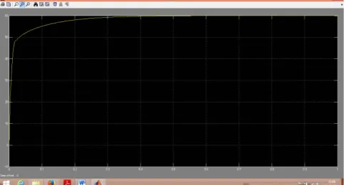
Performance of the renewable Energy sources(RES) Model using PV Module designed as shown in Figure 6.and is predicted using the analysis for the minimum input voltage Vin,min = 40V for different load conditions with an output voltage of Vo = 60V.Design values of various passive components used in the experiment were 1) ZVT boost: boost inductor Lb = 50 μH; resonant inductor La = 300 nH; snubbercapacitor Cb = 220 nF, and 2) LCL SRC: resonant inductor Lr = 3.3 μH, resonant capacitor Cs = 1 μF, parallel inductor Lt = 12 μH, and snubber capacitors Cn 1–Cn 4 = 6.8 nF, HF transformer turns ratio = 10:6. Shows some waveforms obtained with minimum input voltage (40 V) and maximum output power (2.4 kW) at 60-V output.
Simulation Result for Renewable Energy System model using PV Module.
Figure 7.Result for RES model using PV Module
4. Conclusion
This paper presents Renewable Energy System model using PV module, input to the model is given by the PV module and output obtained is as shown in the simulation result shown above. Voltage obtained is approx. 60V DC. This PV model iseasy to configure for a desired PV response characteristics andit directly connects to Sim Power Systems electrical circuit for transitory response analyses. The PV module has two mainparts: A behavioral model of PV cells and a power–limitedelectrical driver forcircuit connection. The behavioral modelestimates voltage and current potential of PV panel for a givensolar radiation (G) and module temperature (Tc) conditions.
Nowadays, solar energy integration in microgrids is suitable primary concern of power system industry.Modeling renewable energy sources for a large-scale powersystem incorporation simulation is more important today,because these simulation tools will be a part of optimal designand intelligent management process.
5. References
[1] Deepak S. Gautam, Ashoka K. S. Bhat, “A Comparison of Soft-Switched DC-to-DC Converters for Electrolyzer Application”, Proceedings of lntemational the IEEE on power Electronics, vol. 28, no. 1, pp: 54-63 ,January 2013.
[2] MilanaTrifkovic, Mehdi Sheikhzadeh, KhaledNigim and ProdromosDaoutidis, “Modeling and Control of a Renewable Hybrid Energy System With Hydrogen Storage”, Proceedings of lntemational the IEEE on control systems technology, vol. 22, no. 1,pp: 169-179 January 2014.
[3] Riccardo Pittini, Zhe Zhang, Michael A.E. Andersen, “Isolated Full Bridge Boost DC-DC Converter Designed for Bidirectional Operation of Fuel Cells/Electrolyzer Cells in Grid-Tie Applications: Technical university of Denmark , Department of Electrical Engineering.
[4] D. Iannuzzi, and M. Pagano, “Efficiency of Hydrogen based Storage Systems for Stand-Alone PV applications: Numerical and Experimental results”, University of Naples, Proceedings of the IEEE © 2009,pp: 555-561.
[5] P. Chandrasekhar and S. Rama Reddy “Performance of Soft-Switched DC-DC Resonant converter for Electrolyzer” , Proceedings of the IEEE International © 2011, pp: 95-100.
[6] Francisco da Costa Lopes and Edson H. Watanabe “experimental and theoretical development of a pem electrolyzer model applied to energy storage systems”, Proceedings of the IEEE International © 2009.,pp: 775-782
[7] Kodjo Agbossou Mamadou L. Doumbia and Adil Anouar, “Optimal hydrogen production in stand – alone renewable energy system”, Proceedings of IEEE © 2005, pp:2932-2936, Canada
[image:3.595.36.279.578.708.2]buck converters”, Proceedings of IEEE © 2004 , pp: 2786-2793, Canada
[9] Ali Elrayyah, Ali Safayet, YilmazSozer and Malik Elbuluk , “Efficient harmonic and phase estimator for single-phase grid connected renewable energy systems”, Proceedings of IEEE transactions on industry applications, vol. 50, no. 1, January/February 2014 pp: 620-630
[10] Juan M. Galvez, Martin Ordonez, “Swinging Bus Operation of Inverters for Fuel Cell Applications with Small DC-Link Capacitance”,. Proceedings of IEEE transactions on Power Electronics, 2013
[11] Bor-Ren Lin, Shih-Kai Chung “Analysis and implementation of a new zero-voltage switching DC converter with less active switches”, Proceedings of the IET Power Electron, © 2014, Vol. 7, Iss. 1, pp: 85-95.
[12] Rui Yang, HongFa Ding, Yun Xu, Lei Yao, and Ying Meng Xiang, “An Analytical Steady-State Model of LCC type Series–Parallel Resonant Converter With Capacitive Output Filter”, Proceedings of IEEE transactions on Power Electronics, vol. 29, no 1, pp: 328-338, Jan 2014
[13] Farhad Pothukattil, Tiju Baby and Prabakaran M , “Isolated dual input dc-dc converter with ZVS for hybrid energy system applications”, Proceedings of International Conference on Advances in Energy Conversion Technologies (ICAECT), pp: 237-240, 2014
[14] Luca Corradini, Daniel Seltzer, Douglas Bloomquist, Regan Zane, Dragan Maksimovi´c and Boris Jacobson “Zero voltage switching technique for bidirectional DC/Dc converters”, Proceedings of IEEE transactions on power electronics, vol. 29, no. 4, April 2014, pp: 1585-1594.
[15] Hector Sarnago, Oscar Lucıa, Arturo Mediano and Jose M. Burdıo, “Direct AC–AC Resonant Boost Converter for Efficient Domestic Induction Heating Applications,” Proceedings of IEEE transactions on power electronics, vol. 29, no. 3,March 2014, pp: 1128-1139
[16] Xiaodong Li, “A LLC-Type Dual-Bridge Resonant Converter, Analysis, Design, Simulation, and Experimental Results,” Proceedings of IEEE transactions on power electronics, vol. 29, no. 8, August 2014, pp: 4313-4321
[17] Xiaohu Liu, Hui Li, and Zhan Wang, “A Fuel Cell Power Conditioning System With Low- Frequency Ripple-Free Input Current Using a Control-Oriented Power Pulsation Decoupling Strategy,” Proceedings of IEEE transactions on Power Electronics, vol. 29, no. 1, January 2014, pp: 159-169
[18] Minsoo Jang and Vassilios G. Agelidis, “A Boost-Inverter Based Battery-Supported Fuel-Cell Sourced Three-Phase Stand-Alone Power Supply,” Proceedings of IEEE transactions on Power Electronics, Feb 2012
[19] Shu-Kong Ki and Dylan Dah-Chuan Lu, “A High Step-Down Transformer less Single-Stage Single Switch AC/DC
Converter,” Proceedings of IEEE transactions on Power Electronics, Vol.28, No.1,Jan 2013, pp:36-44
[20] Sayed Ali Khajehoddin, MasoudKarimi-Ghartemani, AlirezaBakhshai and Praveen Jain, “A Power Control Method With Simple Structure and Fast Dynamic Response for Single-Phase Grid-Connected DG Systems” Proceedings of IEEE transactions on Power Electronics, Vol.28, No.1,Jan 2013, pp:221-233
[21] R.Samuel Rajesh Babu and Joseph Henry, “A Comparative Analysis of DC-DC Converters for Renewable Energy System” Proceedings of the international Multi conference of Engineers & Computer Scientists IMECS March 2012, Vol II
[22] Deepak S. Gautam, and Ashoka K.S. Bhat, “A Two-Stage Soft-Switched Converter for Electrolyser Application,” Fifteenth National Power Systems Conference (NPSC), IIT Bombay, December 2008,pp: 524-529
[23] Samuel Rajesh Babu R and Henry Joseph, “Embedded controlled ZVS DC-DC converter for Electrolyzer application,” International Journal on Intelligent Electronic Systems, Vol. 5, No.1, January 2011,pp:6-10
[24] Deepak Kumar Nayak and S.Rama Reddy, “Simulation of Soft Switched PWM ZVS Full Bridge Converter,” International Journal of Computer and Electrical Engineering, Vol. 2, No. 3, June, 2010, pp:595-601
[25] J. A. Sabate and F. C. Lee, “Off-line application of the fixed-frequency clamped-mode series resonant converter,” IEEE Trans. Power Electron., vol. 1, no. 1, pp. 39–47, Jan. 1991.
[26] A. K. S. Bhat and F. Luo, “A new gating scheme controlled soft-switching DC-to-DC bridge converter,” in Proc. IEEE Power Electron. Drive Syst. Conf. Rec., 2003, pp. 8–15.
[27] S. V. Dhople, A. Davoudi, A. D. Dominguez-Garcia, and P. L. Chapman, “A unified approach to reliability assessment of multiphase DC–DC converters in photovoltaic energy conversion systems,” IEEE Trans. Power Electron., vol. 27, no. 2, pp. 739–751, Feb. 2013.
[28] W. Chen, X. Ruan, and R. Zhang, “A novel zero-voltage-switching PWM full bridge converter,” IEEE Trans. Power Electron., vol. 23, no. 2, pp. 793–801, Mar. 2008.
[29] Andrijanovits A, Vinnikov D, Roasto I, Blinov A, “Three-level half bridge ZVS DC/DC converter for electrolyzer integration with renewable energy systems”, in Environment and Electrical Engineering (EEEIC),10th International Conference , 8-11 May, 2011.
[30] A. Kirubakaran “Renewable and sustainable energy reviews 13”, 2009, pp:2430-2440
Volume: 11 Issue: 5 , Sept. 1996, pp: 731 -742.
[32] http://en.wikipedia.org
[33] D.Kanimozhi, Prof K.Balakrishnan,“A Comparative Study on Various Dc-Dc Converters
Configurations for Industrial Drives”International Journal for Research and Development in Engineering (IJRDE),Methods Enriching Power and Energy Development (MEPED) 2014,
pp: 040-046
[34] Savitha P B,Shashikala M S,Puttabuddhi K L,“Modelling of 250wp Photovoltaic module and itsperformance analysis using MATLAB /SIMULINK”
Proceedings of IRF International Conference, Bangalore 23rd March-2014,pp:34-40
[35] Praveen bansal,“Matlab /Simulink Based-analysis of Photovoltaic Array FedMultilevel Boost Converter”Innovative Systems Design and Engineering.Vol.4, No.7, 2013 - National Conference on Emerging Trends in Electrical, Instrumentation & Communication Engineering, pp 20-27
![Fig 1. Block diagram of typical RES system[5]](https://thumb-us.123doks.com/thumbv2/123dok_us/689536.1076362/1.595.41.275.492.651/fig-block-diagram-typical-res.webp)
![Figure 3.Block Diagram of PV Simulation Model[37]](https://thumb-us.123doks.com/thumbv2/123dok_us/689536.1076362/2.595.319.549.58.160/figure-block-diagram-of-pv-simulation-model.webp)