Volume 4, No. 8, May-June 2013
International Journal of Advanced Research in Computer Science
CASE STUDY AND REPORT
Available Online at www.ijarcs.info
ISSN No. 0976-5697
Virtual-IP Routing Architecture Using OpenFlow
Abhinandan Goti
Dept of Computer Science M.S.Ramaiah Institute of Technology
Bangalore, India [email protected]
Annapurna Patil
Dept of Computer Science M.S.Ramaiah Institute of Technology
Bangalore, India [email protected]
Abstract: This work is aimed to provide an infrastructure for virtual IP routing in a central controller driven architecture. The framework is virtual system which works according to customers requirements in network service areas where the physical architecture of network need not required to change for each customer’s requirement, instead the virtual environment is created for that particular customer. This routing architecture provides several benefits over the traditional routing. In this approach the routing intelligence is maintained by the application software and the controller. Whereas the traditional Networking gears can be replaced by commodity hardware capable of forwarding packets based on flows. The Software Driven Network architecture allows for a larger control by the user in route selection thus satisfying the growing need for a more granular route selection. This opens various new opportunities especially in multi-tenanted networks by enabling to provide routing as a service (RaaS) [1].
Keywords: Openflow technology, Switch Controllers, Virtualization, Open vSwitch, Routing-as-a-Service
I. INTRODUCTION
This chapter would give a brief introduction to the project. We would outline the overview of the system where the project is deployed and where the necessity of this framework arises.
A. System Overview :
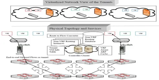
The platform is provided to multiple customers for their routing service, where execution engine will be divided virtually. This framework is composed by an OpenFlow Controller application called Beacon which is deployed in a virtual machine acting as controller server, an independent Routing Server, and a virtual network environment that reproduces the connectivity of a physical infrastructure and runs IP routing engines. The routing engines generate the route information base (RIB) into the Linux IP tables according to the routing protocols configured. In turn, the Linux IP and ARP tables are collected by Beacon controller processes and then translated into OpenFlow [2] tuples that are finally installed in the associated OpenFlow-enabled devices in the forwarding plane.
The main components of the Virtual-IP Architecture are: a. OpenFlow Enabled Switches
b. Beacon Controller running in an vm of ESXi hypervisor c. Routing Engine running in an vm of ESXi hypervisor d. Vswitch deployed using vSphere client in ESXi hypervisor
a) Use of Virtual Routing and forwarding (VRF): VRF provides a way for you to configure multiple routing instances on your router [8]. This is beneficial if you have a need to keep customer traffic and routing separate and you want to utilize the same hardware. Some may be thinking that you can keep customers separate by using sub-interfaces or different physical interfaces, and then use ACL filtering to keep traffic segregated. This would certainly be one method of doing so, however, if for some reason you wanted to overlap customer addressing, you’d have a serious problem. With a VRF you can use the same IP address assigned to two different interfaces on a router at the same time.
Figure 1. Virtual-IP Routing Architecture
B. Use of OpenFlow Technology:
OpenFlow is like an x86 instruction set for the network, which provides open interface to “black box” networking node (ie. Routers, L2/L3 switch) to enable visibility and openness in network OpenFlow provide separation of control plane and data plane. The data path of an OpenFlow Switch consists of a Flow Table, and an action associated with each flow entry.
Figure 2. OpenFlow enabled switch
The control path consists of a controller which programs the flow entry in the flow table OpenFlow is based on an Ethernet switch, with an internal flow-table, and a standardized interface to add and remove flow entries [5].
a. Instruction & Action Set: Each flow entry contains a set of instructions that are executed when a packet matches the entry. Instructions contain either a set of actions to add to the action set, which contains a list of actions to apply immediately to the packet, or
[image:2.612.325.562.432.565.2]modifies pipeline processing. An Action set is associated with each packet. It’s empty by default. Action set is carried between flow tables. A flow entry modifies action set using Write-Action or Clear-Action instruction. Processing stops when the instruction does not contain Goto-Table and the actions in the set are executed.
Figure 3. Packet flow diagram
C. Motivation:
To solve the challenges created by legacy networks, organizations need the ability to automate the network from end to end by leveraging SDN to abstract the control plane from the physical infrastructure.
The OpenFlow technology has provided a framework in which we can implement our new ideas which will help us in providing finer grained network service in virtualized environment (cloud system). Along with above description the following will also considered for the current technology trend.
a) Facilitate Innovation in Network
[image:2.612.53.266.460.610.2]c) Independent innovation at each layer
d) Experiment and research using bulky, non-expensive equipment
e) More accessibility since software can be easily developed by more vendors
f) Speed-to-market – no hardware fabrication cycles g) More flexibility with programmability
h) Ease of customization and integration with other software applications
i) Fast upgrades
j) Program a network vs Configure a network
Through this the existing flow engine which is deployed in network hardware elements can be migrated to software engine where the network developer has the flexibility to implement his experiments that can be run as a software system without altering the existing physical settings.
II. LITERTURESURVEY
In this section, we discuss about how OpenFlow is can be invented and the same can be implemented on current networking elements like switch, routers and gateways. And also we discuss about how the virtual systems can be used to deploy independent execution engines.
A. Related Work:
The Virtual-IP routing architecture has number of hardware and software entities, which are used and configured for the desired framework development. Most of hardware elements require configuration according to physical network stat. Along with all configuration, the software tools required for the same architecture need some prerequisite applications which dependent on one or more software elements.
a. Software Defined Networking: To solve the challenges created by legacy networks, organizations need the ability to automate the network from end to end by leveraging SDN [3] to abstract the control plane from the physical infrastructure,” said Joe Skorupa, vice president and distinguished analyst, Gartner. “For maximum performance, utilization and simplicity, customers must ensure that there is a suite of SDN technologies across the entire network—from the hardware infrastructure to the control plane to the applications, and also from the data center to the desktop—in order to move beyond today’s complexities and improve business agility across the enterprise.
b. Open Flow: The foundation of an open, standards-based software-defined networking (SDN) is the OpenFlow protocol. OpenFlow development started in 2007 and has been collaboration between the academic and commercial worlds. Originally led by Stanford University and the University of California at Berkeley, the standard now is being defined by the Open Networking Foundation (ONF). HP has been a leader in OpenFlow technology since its inception and is a founding member of the ONF. And this technology was essential part our project which provides infrastructure, where the existing technology does not support.
c. Switch Configuration: This section explains how to configure remote and intelligent port mirroring on ProCurve ProVision switches. Remote port mirroring lets you redirect data flows that you monitor on a source switch to a different destination switch, which allows a centralized network analyzer or probe to capture packets for an entire LAN. This is important if you want to add an intrusion detection system (IDS) without introducing an in-line failure point.
You need a Pro Curve ProVision switch [6], such as the ProCurve Switch 5400zl, as the source switch, and at least one other switch (such as the ProCurve Switch 3500yl used in this example) as the destination. You can use ProCurve Manager Plus or the CLI to configure remote and intelligent mirroring. To monitor traffic you need a network protocol analyzer such as Wireshark.
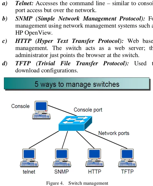
Switch Management: After the hardware has been installed and cabled it is likely that at least a minimal additional configuration would be required. Until an IP address has been assigned configuration is performed using the console port (usually at the rear of the switch). Most switch management options require network access and a valid IP address for the switch. If and when the switch has a network connection and a valid IP address, then a number of options for switch management are possible [4].
a) Telnet: Accesses the command line – similar to console port access but over the network.
b) SNMP (Simple Network Management Protocol): For management using network management systems such as HP OpenView.
c) HTTP (Hyper Text Transfer Protocol): Web based management. The switch acts as a web server; the administrator just points the browser at the switch.
[image:3.612.319.568.344.647.2]d) TFTP (Trivial File Transfer Protocol): Used to download configurations.
Figure 4. Switch management
Figure 5. Open Virtual Switch
So, it is reasonable to ask why Open vSwitch is used. The answer is that Open vSwitch is targeted at multi-server virtualization deployments, a landscape for which the previous stack is not well suited.
These environments are often characterized by highly dynamic end-points, the maintenance of logical abstractions, and (sometimes) integration with or offloading to special purpose switching hardware.
III. PROBLEMSPECIFICATION
This chapter gives a detailed description of the problem statement of the project.
A. Problem Statement:
a. To provide RaaS in multitalented network with often changes in requirement [1].
b. Migration of path from legacy IP deployments c. Resolving Subnet Infrastructure
d. Need for network Virtualization. e. Interoperability with legacy equipment’s
B. Problem Description:
The development of virtual-ip architecture will help in providing routing service in current networking infrastructure where traditional Networking gears need to be replaced by commodity hardware capable of forwarding packets based on flows. The current technology requirement need for flexibility in networking operation. The Software Driven Network architecture allows for a larger control by the user in route selection thus satisfying the growing need for a more granular route selection.
IV. SOFTWAREREQUIREMENTSECIFICATION
The software requirements specification (SRS) represents a complete description of the behavior of the software to be developed. The SRS is often referred to as the parent document because all subsequent project management documents, such as design specifications, statements of work, software architecture specifications, testing and validation plans, and documentation plans, follow it. Software requirement specification will contain states what the software will do. What the software has to do is directly
perceived by its users – either human users or other software systems. The common understanding between the user and developer is captured in requirements document. The writing of software requirement specification reduces development effort, as careful review of the document can reveal omissions, misunderstandings, and inconsistencies early in the development cycle when these problems are easier to correct. The SRS discusses the product but not the project that developed it; hence the SRS serves as a basis for later enhancement of the finished product. The SRS may need to be altered, but it does provide a foundation for continued production evaluation.
A. Purpose:
To develop architecture for the multi tenanted network to provide routing as a service using virtualized environment. Through this architecture the service provider will be having flexibility over the physical network to configure according to the multiple customer requirements.
B. Scope:
This is the alternative for the existing system where traditional Networking gears can be replaced by commodity hardware capable of forwarding packets based on flows using OpenFlow technology.
C. Objective:
The primary objective of this project is to provide an infrastructure for virtual IP routing in a central controller driven architecture.
This routing architecture provides several benefits over the traditional routing. In this approach the routing intelligence is maintained by the application software and the controller.
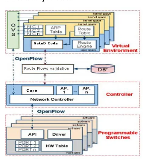
D. Functional Requirement:
[image:4.612.325.560.429.690.2]In software engineering, functional requirement defines a function of a software system or its component. A function is described as a set of inputs, the behavior, and outputs. Functional requirements may be calculations, technical details, data manipulation and processing and other specific functionality that define what a system is supposed to accomplish. Above diagram is the schematic representation of the whole system where the work flow is divided according to functional operation of architecture.
E. Software Requirement:
a. Cent OS version 6 and above – Base platform b. Eclipse Indigo – Development environment for
beacon
c. VMware vSphere client 5.1 – Interface for ESXi management
d. Vnc server – GUI access Prerequisites: OpenFlow switch OS, Beacon Java Based Controller, Open Vswitch
F. Hardware Requirement
a. ESXi hypervisor – For virtual machine deployment Consists following specification
a) 8 GB shared memory system
b) 550 GB Secondary Memory
c) 6 core of 2 slot multiprocessor
d) 2 Intel core Network Adapter
b. HP network switch – HP ProCurve 3350 (24 port operator)
c. IXIA hypervisor server and card slots
d. Link cables for interconnecting the whole system.
V. ANALYSIS
Analysis focuses on producing a model of the system, called the analysis model, which is correct, complete, consistent, and verifiable. The analysis model represents the system under development from the user’s point of view.
A. Existing Routing System:
Traditional Routing System: Routing is the process of selecting paths in a network along which to send network traffic. Routing is performed for many kinds of networks, including the telephone network (circuit switching), electronic data networks (such as the Internet), and transportation networks. It is concerned primarily with routing in electronic data networks using packet switching technology.
Network router is a device or a piece of software in a computer that forwards and routes data packets along networks. A network router connects at least two networks, commonly two LANs or WANs or a LAN and its ISP network. A router is often included as part of a network switch. A router is located at any where one network meets another, including each point-of-presence on the Internet. A router has two key jobs:
a. The router ensures that information doesn't go where it's not needed. This is crucial for keeping large volumes of data from clogging the network.
b. The router makes sure that information does make it to the intended destination.
Figure: 7 Traditional Routing system
B. Proposed Routing System:
Routing using OpenFlow Technology: In the OpenFlow based routing system the porting information can be handled by the controller which is connected to standard switch through openflow protocol with SSL link. The packets can be captured on openflow controller and can be manipulated according to users wish. In this work we are using Beacon
as a openflow controller which is JAVA package based application running in a virtual machine [5].
Figure: 8 OpenFlow Routing system
VI. SYSTEMDESIGN
The purpose of the design phase is to solve the problem specified in the requirements document. The design of the system is most critical factor affecting the quality of the software and has a major impact on the later phases, particularly testing and maintenance. System design aims at identifying the modules that should be in the system, the specifications of these modules and to interact with each other to produce the desired results. At the end of the system design, all the major modules in the system and their specifications are decided.
A. Modeling:
This chapter models the virtual-IP routing architecture through various UML diagrams.
a. Use case View: To provide a basis for planning the technical contents of the iterations, an architectural view called the use-case view is used in the requirements discipline. It captures system functionality as seen by users. It is built in the initial stage of development. It is developed by analysts and domain experts. It provides a description of the system behavior which is documented in a use case model.
The below (figure 9) diagram explains about how user/customer is requesting for routing as a service and how all the events are interacted with each other. As per the use case diagram above we have use case called request for RaaS, where it include the event use cases where ip deployment and flow is been defined. Here customer and controller are the actors which handling and giving the input to events. We have the following use cases which related to the respective actors.
Figure: 9 Use case Diagram: Routing as a service operation
Figure: 10 Use case Diagram: Switch/Router Operation based on OpenFlow
b. Class View
Figure: 11 Class Diagram: Controller, Router with User
B. Implementation Plan:
The development virtual-IP routing architecture can be carried out by breaking the entire project into following modules.
a. Dividing execution engine in multiple vm’s b. Configuring traffic mirrors for all vm’s c. Calculating set of Flows through controller d. Validation of route flows – algorithmic validation e. Routing task based on validation – Database interface
(RIB).
VII. CONCLUSION
The use of OpenFlow technology in this work has provided a platform where software defined architecture can be developed which is a Virtual-IP based routing system which provides several benefits over the traditional routing.
In this approach the routing intelligence is maintained by the application software and the controller where routing instance are generated and validated according to the users requirement, and it is been run on the virtual network instance created as per the physical infrastructure.
This opens various new opportunities especially in multi-tenanted networks where flexibility can be achieved in routing the data on virtual instance of network where most of issues associated with tradition routing can be overcome using this technique.
VIII. REFERENCES
[1] “Routing as a Service” by Karthik Lakshminarayanan, Ion Stoica Scott, Shenker University of California, Berkeley & Jennifer Rexford Princeton University – princeton education 2005.
[2] “Revisiting IP Routing Control Platforms with OpenFlow-based Software-Defined Networks” by Christian Rothenberg, Marcelo Nascimento & Marcos Salvador - Telecomm. Research and Development Center Campinas, SP, Brazil – ACM Sigcomm Conference 2012.
[3] Online : https://www.opennetworking.org/ - Details on Software driven network and opnflow.
[4] Online : http://www.networkers-online.com/ - Deaitls about configuration of network
[5] Online: http://www.openflow.org/wp/wpcontent/uploads/2011/07/GENIWorkshopWhitepaper.pdf -Details about openflow protocol, network controllers
[6] Online: http://h20195.www2.hp.com/v2/GetPDF.aspx/4AA3-8562ENW.pdf - Details Switch configuration
[7] Online: http://www.netheaven.com/Tunnel.html - Details aobut routing and tunneling
[8] Online;