78:6–6 (2016) 81–86 | www.jurnalteknologi.utm.my | eISSN 2180–3722 |
Jurnal
Teknologi
Full Paper
A
F
UZZY
L
OGIC
C
ONTROLLER TO
L
INE
S
TARTING
P
ERFORMANCE
S
YNCHRONOUS
M
OTOR FOR A
C
RANE
S
YSTEM
U
SING
V
ECTOR
C
ONTROL
Birowo
a, Robiah Ahmad
a*, Hairi Zamzuri
a, Agus Priyono
ba
UTM Razak School of Engineering and Advanced Technology,
Universiti Teknologi Malaysia, 54100 Kuala Lumpur, Malaysia
b
Institut Sains Teknologi Nasional, Jakarta, Indonesia
Article history
Received 18 July 2015 Received in revised form
19 December 2015 Accepted 21 January 2016
*Corresponding author
[email protected]
Graphical abstract
Abstract
This paper presents the design process of a synchronous motor of crane system using vector control of line starting [1]. The preliminary design is d-q model armature rotor line start synchronous motor with vector control for decreasing a starting current and torque. The design allows the synchronous motor to operate at both starting and synchronous speed. The basic equations for park transformation of the rotor-stator for proposed vector control to synchronous motor are presented [2]. The starting performance of synchronous motor, for example in crane application, requires rapid dynamics and precise regulation; hence the need of direct control is becoming an urgent demand. This type of control providesanindependent vector control of torqueand current, whichis similar to a separatelyexcited synchronous motor and offersa number ofattractivefeatures. Synchronous motorhasahighstartingtorquewhileseparately s y n c h r o n o u s motorcanoperate abovethebase low speedinthe line starting current [3]. This paper designs study and highlights the effectiveness of the proposed vector control methods for a line starting performance of synchronous motor model parameter, using a fuzzy logic controller methods both simulation and manufacturers measured experimental data. Asteady state and transient analysis of the synchronous motor is performed belowand abovebase line starting current.
Keywords: Synchronous motor, line starting current, crane; vector control, d-q
© 2016 Penerbit UTM Press. All rights reserved
1.0 INTRODUCTION
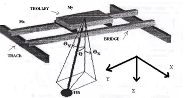
A crane system in industry is used to move and up-down heavy objects either continuously or discontinuously over a certain distance in Figure1. The main function is distributing materials and equipment in the vertical direction. Operational performance characteristics of a good crane include its starting performance, acceleration and braking. The main component of the crane plane is the electric motor [4]. Synchronous motor was traditionally used since it has a low starting torque [5]. Below base speed, the flux is kept constant therefore the torque developed is proportional to armature current and the motor speed can be controlled by armature voltage.
Setting motion in goods move plane carried by synchronous motor can be adjusted by changing armature current in the stator and rotor torque [6].
Figure 1 Conversion model of Mechanic – Electro State variables of the equation are:
Load of Conveyor
Parameter Synchronous Motor with d-q model
Using Vector Control
Fuzzy Logic Controller
My= sling position in hoist in horizontal plane = y (m) x2= hoist crane movement angle in vertical plane
= (radian ).
x3=hoist crane movement speed in horizontal
plane (m/sec)
x4= hoist crane angle movement speed
(radian/sec)
Many fuzzy logic controller used in automation control cause employing knowledge base and linguistic expression that be able to represented human operator work mechanism. Controlling with fuzzy logic derived heuristically based on process condition and operator experiences then did not need mathematic model from plant that will be controlled [7]. Fuzzy logic controller expected is able to changes value automatically from PID controller parameter appropriate with changes happen on system, then system performance, in this case settling time, rise time, and error steady state suitable with wished criteria. From description above emerge a problem in implementing fuzzy logic to change gain PID controller value in three phases induction motor speed control to get expected performance.
Therefore the synchronous motor starting current can be controlled accurately. There are fuzzy logic controller methods of setting the starting current of the synchronous motor and in this vector control based is compares to analyze and determine the best [8]. There is another method in which a field current and torque settings are automatically set by the controller and is called vector control of synchronous motor. Simulation studies are conducted to the motor drives as to perform as synchronous motor below base speed as to get high starting torque while above the base speed, the motor operates as conventional separately excited DC motor and the speed is controlled by controlling armature current.
2.0 ANALYSIS AND EXPERIMENTAL
2.1 Mathematical Model
Load dynamics in an electric drive with rigid mechanical coupling between synchronous motor and crane load is described by the equation [9]:
Jt .dՈt, / dt = Te – Tfriction - Tload (1)
Tfriction = Ts + TC + TV + TW (2)
Since there are no electrical sources connected directly to the round rotor synchronous motor. The round rotor synchronous motor is capable of bilateral power flow, thus it can operate in the motor mode modeled by the per phase equivalent circuit of Figure 2 [10].
Vd Salfa-d
SL-dm id
rs SLs i-dm
id
r-dr r-qr i-dr i-f
SL-dr SL-qr i-fl
Vf
Wr-alfa-q
Vq
Salfa-q SL-qm iq
rs SLs i-qm
iq
r-qr i-qr
Wr-alfa-d
Figure 2 Synchronous motor of equivalent circuit curves
2.2 Machine Equations in the Rotor Reference Frame
The proposed machine is of the cylindrical rotor design, without taking into consideration the effects of saturation, slotting, eddy current, damper windings in Figure 3.
Figure 3 Rotor reference frame of synchronous motor
2.3 Vector Control Mode of Operation
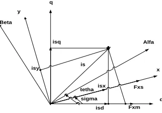
As stated above, it is advantageous to operate the synchronous motor in a vector control mode of operation. Therefore, no problem concerning the stability arises, and smooth starting is achieved. The possibility of operating the motor at zero power angles is achievable, with unitypower factor in the constant torque region. The motor is controlled to operate with zero power angle from the inverter side and zero direct axis current from the rotor excitation side [14]. Therefore, it operates with minimum stator current and with unity power factor. This mode is practically achieved by providing the voltage source inverter, which feeds the stator-rotor applied voltage, by a control input signal, through which the initial stator applied voltage angle with respect to the measured rotor angle can be adjusted to any arbitrary value. At the same time, the frequency of the inverter output voltage is attached to the rotor current controller.
q y
Beta
Alfa
x
d isq
isy is
isx
isd Fxm Fxs tetha
2.4 Voltage Sources Inverter
The stator of the synchronous motor is fed from a voltage source inverter. A speed encoder is attached to the rotor to detect the rotor speed and the rotor angle. The output speed signal of the speed encoder is connected to one of the inputs of the inverter. This is done while the rotor angle is used as a reference to adjust the initial angle of the applied voltage. The fundamental components of the three-phase voltages of the three-three-phase inverter are given by[12]:
va = √2. Vs. cos Өv (3)
vb = √2. Vs. cos ( Өv – (2π / 3)) (4)
vc = √2. Vs. cos ( Өv – (4π / 3)) (5)
Where Өv= ∫ωe (£).d£ + Өv(0), Өv(0) is the initial angle
of the applied voltages. This initial angle can be easily controlled from the inverter and it plays an important role in the operation of the vector control synchronous motor. Furthermore, it expresses the angle of delay or advance of the switching of the voltage source inverter relative to the measured rotor position. In the rotor reference frame and by substituting for ωe = ωr (2)-(4) are transformed to
Vq = √2. Vs. cos [Өv(0) – Өr(0)] (6)
Vd = -√2. Vs. sin [Өv(0) – Өr(0)] (7)
For Өr(0) = 0, (5) and (6) become
Vq = √2. Vs. cos Өv(0) (8)
Vd = -√2. Vs. sin Өv(0) (9)
2.5 Vector Control of Synchronous Motor
The basic principle in control of synchronous motor drives based on vector control. The flux position can be determined by the moment inertia position sensor because the magnetic flux generated by synchronous motor is fixed in relation to the rotor moment position. To ensure the vector control of the synchronous motor, the technique id = 0 is the optimal
strategy where the motor produce the maximum torque. If id is forced to be zero by closed loop
control, then [13]:
Te = 1.5PLm ( if1.iq )
Φd =Φf (10)
And
Te = 1.5*P* Φf*Iq (11)
Since Φf is constant the electromagnetic torque is the directly proportional to current iq. The torque equation
is similar to that of separated excited DC motor. It is evident from equations (10) and (11) that the starting control can be achieved by controlling the q-axis
current component iq as long as the d-axis current id
is maintained at zero [14].
Figure 4 Vector Control Structure of the Synchronous Motor Drive
2.6 Fuzzy Logic Based
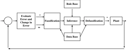
The Structure of a complete fuzzy control system is composed from the following blocs: Fuzzification, Knowledge base, Inference system and Defuzzification. Figure 5 shows the structure of a fuzzy logic controller.
Figure 5 Structure of a fuzzy logic controller
2.7 A Fuzzy Logic Controller
The fuzzification module converts the crisp values of the control inputs into fuzzy values. A fuzzy variable has values which are defined by linguistic variables such as low, medium, high, big etc. Where each is defined by a gradually varying membership function. A fuzzy control essential embeds the intuition and experience of a human operator and sometimes those of a designer and researcher. The data base contains a description of input and output variables using fuzzy sets. The rule base is essentially the control strategy of the system. It is usually obtained from expert knowledge or heuristics; it contains a collection of fuzzy conditional statements expressed as a set of IF-THEN rules, such as [15]:
R(i) : If x1 is F1 and x2 is F2 …. And xn is Fn
Then Y is G(i), i = 1, ….,M 12)
Where: (x1,x2,…,xn) is the input variables vector, Y is the control variable, M is the number of rules, n is the
PWM INVERTER dq - abc
ids I ref
Speed Sensor
Iqs-ref
SYNCHRONOUS MOTOR
dq - abc iqs PID
Iqs Ids
Speed Reference
current
Wr
Diode Bridge Rectifier
Sinle Pulse 50 Hz, AC
Suply
Capacitor
Ids-ref
Vds-ref
Vqs-ref
emf-q emf-d
Int
Evaluate Error and Change in Error
Fuzzification Inference
Data Base Rule Base
Defuzzification Plant
u e
number fuzzy variables, (F1,F2, …,Fn) are the fuzzy sets.For the given rule base of a control system, the fuzzy controller determines the rule base to be fired for the specific input signal condition and then computes the effective control action.
The general structure of a complete fuzzy logic control system is given in Figure 6. The plant control u is inferred from the two state variables, error ( e ) and change in error De [16]. The actual crisp input are approximates to the closer values of the respective universes of discourse. Hence, the fuzzified inputs are described by singleton fuzzy sets. The elaboration of this controller is based on the phase plant. The control rules are designed to assign a fuzzy set of the control input u for each combination of fuzzy sets of e and De [17].
Figure 6 Membership functions for input e
Figure 7 Membership functions for input De
Figure 8 Membership functions for output u
2.8 A Fuzzy Logic Controller Based Dtvc for Synchronous Motor
The experimental of fuzzy logic starting current control of synchronous motor has emerged as one of the challenging tasks in the control system. The generalized block diagram of starting current control of synchronous motor shown in Figure 2.
PWM INVERTER dq - abc
ids I ref
Speed Sensor
Iqs-ref
SYNCHRON OUS MOTOR
dq - abc iqs FLC
Iqs
Ids
Speed Reference
current
Wr
Diode Bridge Rectifier
Sinle Pulse 50 Hz, AC
Suply
Capacitor
Ids-ref
Vds-ref
Vqs-ref
emf-q emf-d
Int
Figure 9 Fuzzy Logic Controller Based DTVC scheme
Fuzzy logic controller is used in the place of PI controller. The fuzzy logic has been applied to estimate torque, speed and current of the motor at any instant of time comparing the starting torque and current with desired set values generates the error signal which is used to compensate the error. The fuzzy logic controller compares the actual values to set values and accordingly controls the firing of power electronics instruments, which can be a Triac, IGBT, power electronics or any other suitable devices.
3.0 RESULTS AND DISCUSSION
3.1 Full Analysis Setup
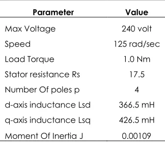
Table 1 shows the SynchronousMotor parameters. The Simulation system is setup by mathematical modeling will be results for a Vector Control system when fuzzy Logic Controller to the synchronous motor for following parameters:
Table 1 SynchronousMotor Parameters
Parameter Value
Max Voltage 240 volt
Speed 125 rad/sec
Load Torque 1.0 Nm
Stator resistance Rs 17.5
Number Of poles p 4
d-axis inductance Lsd 366.5 mH q-axis inductance Lsq 426.5 mH Moment Of Inertia J 0.00109
Simulation was performed to show the performances of the technique used in this section and based on fuzzy logic controller for the control of the synchronous motor. Figure 3 and Figure 4 represent the starting torque and starting current for conventional and fuzzy logic controller based vector U
NB NM ZR PM PB
0 a1_e a2_e
-a1_e -a2_e
U
NB NM ZR PM PB
0 a1_e a2_e
-a1_e -a2_e
U
NB NM Z PM PB
Ueq Ueq-Kf/2
control methods. Comparatively the starting torque and starting current in Figure 3 is reduced compared to conventional vector control method in Figure 4. In Figure 5 and Figure 6 no load starting transient in conventional and fuzzy logic controller based vector control methods are represented.
Figure 3 Conventional VC: No Load Starting Transient
Figure 4 Proposed Fuzzy Logic-VC: No Load Starting Transient
Figure 5 Conventional VC: Transient during speed reversal
Figure 6 Proposed Fuzzy Logic-VC: Transient during speed reversal
From Figure 3 and Figure 5 for conventional and proposed vector control methods the starting torque and starting current values are represented with no load and load in Table 2. From Figure 4 and Figure 6 for fuzzy logic controller and proposed vector control methods the starting torque and starting current values are represented with no load and load in Table 2.
Table 2 Comparison of Conventional and Fuzzy Logic Controller based Vector Control methods
Method Starting Torque (Nm) Starting Current (A) Conventional
Vector Control 1.1 ( No Load ) 1.2 (No Load)
Fuzzy controller based Vector
Control 0.9 (No Load) 1.0 (No Load)
Conventional
Vector Control 1.3 ( speed reversal ) 1.25 ( speed reversal )
Fuzzy controller based Vector
Control 1.05 (speed reversal ) 1.15 (speed reversal )
3.2 Object Highlighting
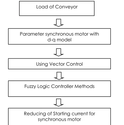
The second part of the designs study is highlighting the effectiveness of the proposed vector control methods for a line starting performance of synchronous motor with d-q model parameter, using a fuzzy logic controller methods both simulation and manufactures measured experimental data. Figure 7 shows block diagram of the processes system decreasing starting current for synchronous motor with fuzzy logic controller.
Figure 7 Block Diagram of the starting current controller of the system
Load of Conveyor
Parameter synchronous motor with d-q model
Using Vector Control
Fuzzy Logic Controller Methods
4.0 CONCLUSION
The paper presents a new approach to starting current control for synchronous motor. The paper develops a simple analysis controller to deal with parameters uncertain and external disturbance and takes full account of system noise, electronic implementation and integral control. The control strategy is based on fuzzy logic controller approaches. A complete fuzzy logic control based synchronous motor has been described. The system was analyzed and designed and performances were studied extensively by simulation to validate the theoretical. The simulation results show that the proposed controller is superior to conventional controller in analysis and in tracking precision. The simulation study clearly indicated the superior performance a fuzzy logic control, because it is inherently adaptive in nature. It appears from the response properties that it has a high performance in presence of the plant parameters uncertain and load. The control of starting current by fuzzy logic control gives fast dynamic response with no overshoot and negligible steady-state error.
Acknowledgment
The authors would like to thank Ministry of Education (MOE) Malaysia, Universiti Teknologi Malaysia (UTM), InstitutSainsdanTeknologi Nasional, (ISTN) Jakarta and Politeknik NSC Surabaya, Indonesia for the support provided throughout the course of this research.
References
[1] Slemon, G. R. 2012. Electric Machines and Drives. Four- edition. Addison Wesley.
[2] Vas, P. 2011. Vector Control of AC Drives. Five-edition. Englewood Cliffs, New Jersey: Prentice Hall.
[3] Mahmoud, I., Masoud, Jhon E. Flecher, and Barry William, W. March 2010. Decoupled Control ofRotorTorque and Rotor Electric Power Delivered in a Salient Pole, Synchronous Machine. IEEE Trans. Energy Conv. 20(1). [4] Mehta S. and Chiasson, J. Feb.2011. Nonlinear Control Of
A Series DC Motor: Theory And Experiment. IEEE
Transaction on Industrial Electronics. 45(1): 134-141.
[5] Zong Liu, Z., Lin Luo, F. and Rashid, M. H. March- April. 2013. Speed Nonlinear Control of DC Motor Drive with Field Weakening. IEEE Transactions on Industry
Applications. 39(2): 417-423.
[6] VerschoofIng, J. 2012. Cranes Design, Practice, and
Maintenamce. Four-edition. London: Professional
Engineering Publishing Limited.
[7] Alaa A. Al-Saffar. 2014. PI-Like Fuzzy Logic Direct Torque Control of PMSM. International Journal of Current
Engineering and Technology. 4(1).
[8] Rashid Muhammad, H. 2012. Circuits, Devices, and
Applications in Power Electronics. Four editions. Upper
Saddle River, NJ: Prentice-Hall.
[9] T. Wildi. 2012. Electrical Machines Drives, and Power
Systems. Fifth edition. Prentice Hall.
[10] N. Mohan, T. M. Undeland and W. P. Robbins. 2010. Power
Electronics Converter, Applications and Design. Third
edition. New York: Wiley Press.
[11] R. Krishnan. 2011. Electrical Motor Drives: Modeling,
Analysis, and Control. Four edition. Prentice Hall.
[12] Zeid, Saad M. December 2010. An Analysis of Permanent
Magnet Synchronous Motor Drives. Master thesis.
Memorial University, New Foundland.
[13] Sen, P. C. 2010. Principles of Electric Machines and Power Electronics. six-edition. John Wiley & Sons, Inc.
[14] Sarma, M. 2011. Electric Machines. Six edition. PWS Publishing Company.
[15] Thaler, G., Wilcox, M. I. 2010. Electric Machines Dynamics
and Steady State. Five edition, John Wiley & Sons Inc.
[16] Krause, P. C., O. Wasynczuk, S. D, Sudhoff. 2010. Analysis of
Electric Machinary and Driver Systems. Four edition. IEEE
Press and Wiley Interscience.
[17] Dewantoro, G. 2011. Robust Speed Controlled Permanent Magnet Synchronous Motor Drive Using Fuzzy Logic Control. International Conference on Fuzzy Systems. June 27-30. Taipei, Taiwan.
[18] Maamound, A. and Alsayed, Y. M. 2013. Fuzzy Logic Based Speed Controller for Permanent Magnet Synchronous Motor Drive. International Conference on
Mechatronics and Automation. August 4-7. Takamatzu,
Japan.
[19] Aissoui, A. G.2011. Fuzzy Logic Controller for Synchronous Motor. Journal of Electrical Engineering. 58(5): 285-290. [20] Mishra, S. and Tomer, A. S. 2014. Speed Control of PMSM
Drives by Using Neural Network Controller. Advance in
Electronic and Electric Engineering. ISSN 2231-1297. 4(4):
353-360.
[21] Al-Harthi Mosleh, M. 2012. Control of PMSM Using Artificial Neural Networks. Advances in Electrical Engineering. 1(3). [22] Sudhakar, A. 2013. Neural network controller in direct
Torque controlled Synchronous Motor. International Journal of Power Electronic and Drive System (IJPEDS).