DOI: 10.11591/ijeecs.v5.i3.pp488-495 488
Distribution Power Loss Minimization via Distributed
Generation, Capacitor and Network Reconfiguration
Mohd Nabil Bin Muhtazaruddin*,1, Nurul Aini Bani1, Siti Armiza Mohd Aris1, Siti Zura A. Jalil1, Hazilah Mad Kaidi1, Abdul Yasser Abd Fatah1, Jasrul Jamani Jamian2, Firdaus
Muhammad-Sukki3, Siti Hawa Abu-Bakar4
1
UTM Razak School of Engineering and Advanced Technology, Universiti Teknologi Malaysia, Malaysia
2
Fakulti Kejuruteraan Elektrik, Universiti Teknologi Malaysia, Malaysia
3
School of Engineering, Robert Gordon University
4
Universiti Kuala Lumpur British Malaysian Institute, Malaysia *Corresponding author, e-mail: [email protected]
Abstract
This paper presents a solution to solve the network reconfiguration, DG coordination (location and size) and capacitor coordination (location and size), simultaneously. The proposed solution will be determined by using Artificial Bee Colony (ABC). Various case studies are presented to see the impact on the test system, in term of power loss reduction and also voltage profiles. The proposed approach is applied to a 33-bus test system and simulate by using MATLAB programming. The simulation results show that combination of DG, capacitor and network reconfiguration gives a positive impact on total power losses minimization as well as voltage profile improvement compared to other case studies.
Keywords: power loss minimization, distributed generation, capacitor, network reconfiguration, artificial bee colony
Copyright © 2017 Institute of Advanced Engineering and Science. All rights reserved.
1. Introduction
Increased of power losses in distribution system is a major challenge that needed to be addressed by the utilities. With demand for electricity is expected to intensify in the future, the utilities are forced to find ways to reduce the power losses, hence increase the system efficiency. Furthermore, it also could push all the equipments to operate at maximum loading that could lead to equipment failure. Revamp the existing power system is not a practical solution that should be done by the utilities due to the increment in the investment and capital costs. Therefore, researchers had introduced several approaches that can be implemented without having a major construction to the existing system such as Network Reconfiguration (NR) process, installing capacitor and insertion of Distributed Generation (DG). All of these solutions have been widely used by the researchers/engineers to mitigate power losses that existed in the distribution network.
Another approach of reducing the power losses is by installing capacitor. The objective of this approach is to inject certain amount of reactive power into the distribution system, to improve the voltage profile and later reduce the power losses. Similar to the NR approach, there are many techniques that had been proposed by researchers to solve the capacitor problem. These techniques can be categorized into four which are analytical, numerical, heuristic and artificial intelligent [8] had reviewed in details regarding capacitor placement conducted by previous researchers. Also, comparison of different methods to determine capacitor placement are performed. Basically, the solution of capacitor placement is done separately. The location of the capacitor is done by using sensitivity analysis, whereas, for the size of the capacitor is calculated using meta-heuristic methods such as PSO [9], ABC [10], Plant Growth Simulation Algorithm (PGSA) [11], and GA [12]. However, this will force the solution to trap in local optimum (meaning not the best solution) due to pre-determine of location by using sensitivity analysis is not considered the best value of size. To alleviate such problem, some of the authors had determined locations and sizes of capacitors simultaneously that usually done by using meta-heuristic [13]. In term of solutions for both approaches, determination of sizes and locations for capacitor simultaneously gives better results as compared to separate analysis [13].
Besides aforementioned methods to minimize the losses, integration of DG with distribution network is another popular approach chosen by the researchers. There are many research papers had been published to see the impact of installation of DG. Among the advantages offered by the DG are power loss reduction, voltage profile improvement and stability index enhancement [14]. However, all of these benefits are not obtained if the calculation of size and location for the DG is not properly determined [15]. Similar to the capacitor, the same methodology can be used to determine optimal location and size of the DG. Some examples of methods that had been applied to solve DG coordination are Evolution Programming (EP) [16], PSO [17], ABC [18], GA [19] and Firefly Algorithm (FA) [20]. In addition, authors [21] proof that coordination for location and size of DG done simultaneously compared to separate analysis (location is determined first before calculation of the size) gives better results.
Generally, most researchers focus only on either the NR or capacitor installations or DG allocation. However, the solution is still less effective in reducing the power loss. Therefore, there are a number of suggestions put forward by researchers to combine these methods to get better results. The authors [22, 23] suggested a combination of the NR with the capacitor. Later, a combination of DG and capacitor is introduced [24, 25] as well as a combination of DG and NR [26, 27]. All of the combinations give better power loss reduction compared if a single method is used. Recently, several papers have proposed to solve these three methods, simultaneously. The authors solved by using tabu search method [28]. They successfully showed that combination of DG, capacitor, and NR gives better results. However, this solution still not give best results due to the authors already pre-determined the locations and sizes of DG and capacitor. This will lead the solution to trap in a local optimum. Similar in [29], they determined the location for both DG and capacitor by using sensitivity index to reduce the search space. The authors in [30] also already assumed the DG and capacitor installed. They solved the solution by using PSO. Overall, the combination of all these three methods provides better power loss reduction. However, in the above-mentioned references, they still not fully determine all parameters (switches for NR, locations, and sizes for DG and capacitor) using a single method. Therefore, this paper proposes a solution to solve all parameters by using ABC in a single computation.
The rest of the paper is organized as follows: Section 2 provides a methodology to solve the proposed method. Section 3 presents the results and discussion for different case studies. The last section concludes this research paper.
2. Research Method
referring to the word “beyond” based on the Oxford dictionary, while the word “heuristic” is a process to learn something by them. Basically, meta-heuristic can be categorized into two groups based on the initial solution which are trajectory and population. Some examples under population-based for meta-heuristic are: GA, PSO, ABC, ACS, and FA. For this research paper, the ABC method is selected due to simplicity and only has two parameters that needed to be tuned.
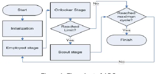
The ABC was introduced by Karaboga [32] in 2005. The concept of this optimization is following the behavior of a swarm of bees to find foods, which involved four stages as illustrated in Figure 1. For tuning process, a size of colony and limit is determined by using trial-and-error method before the start of the optimization process. The ABC process starts with initialization process, which all the bees randomly find the food location (parameter value that needs to be optimized). All the information wil be store and evaluate by using Equation 1. All these information will be used by employed bees during the second stage to find new food location by using Equation 2. Similarly for the third stage, onlooker bees will use the information obtained from the employed bees and find new food location, but, the probability the foods are chosen by the onlooker bees depends on the value of nectar by using Equation 3. For the last stage, one bee that is known as scout bee will find a new food location once the food is depleted. All the process is repeated until maximum cycle acieved.
Figure 1. Flow chart of ABC
(1)
where Fiis the fitness for the objective function and Obj. Funci (Total power loss) is the target of
the study.
(2)
where xij new
and xij old
are the new and previous value of variable (either switches or DG location or DG size or capacitor location or capacitor size), respectively. xkj is a neighbor value that is
selected randomly from jth dimension and range(0,1) is a random value between 0 and 1.
(3)
where probi is the probability, and N is a number of employed bees.
3. Mathematical Formulation
Main target of this research is to see the impact of power loss reduction when harmonization between switches, location, and sizes for both DG and capacitor are done. Therefore, Total Power Loss (TPL) in the distribution system is selected as a main target
i
i
Obj.Func 1
1 F
kj
old ij old
ij new
ij
x
range
x
x
x
(
0
,
1
)
Ni i i i
F
F
prob
(objective function) in the ABC optimization. The objective function in the system is formulated as in Equation 4.
(4)
where L is a number of branches, IL is branch current, and RL is branch resistance.
Besides achieving the main objective to reduce the power losses, optimal selection of parameters that has been determined by the ABC must fulfill all constraints. This process is an important procedure that needed to be observed during optimization process so that the solution will not violate any limits. All constraints that are used during optimization process are listed:
Size of DG constraint:
(5)
where PDG is the size of the DG. For this study, the minimum and maximum size of DG is 0.3
MW and 3 MW, respectively. a) Power balance constraint:
TPL
P
P
P
DG
Substation
Load
(6)The summation of total power supply by substation and power output from the DG must be equal to the total size of load plus total power losses.
b) Radial circuit constraint:
For each of network reconfiguration process, the network must maintain its radial circuit. c) Size of capacitor constraint:
To ensure the selection of size for the capacitor is of practical value. Only five values will be chosen (300, 600, 900, 1200 and 1500 kVar).
d) Voltage bus constraint:
05
.
1
90
.
0
V
n
(7)where n is a number of buses in the distribution system.
4. Results and Analysis
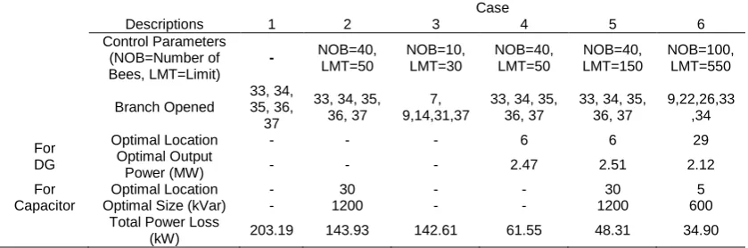
Several case studies have been used as in Table 1. For Case 1, the simulation is done without any approaches imposed. Basically, the power loss during this case is the original power losses for the test system. For the second case (Case 2), capacitor is considered to see the impact on power loss minimization. Both of location and size for the capacitor are determined by using ABC optimization. On the other hand, Case 3 only considers network reconfiguration process by selecting the optimal topology (by switch ON/OFF of the switches). For Case 4, the process is similar like the Case 2, but instead of the capacitor, the DG will be used. For this research, all DG are assumed to operate in Power-Voltage (PV) mode. For second last case (Case 5), a combination between the DG and capacitor is investigated. Lastly, for Case 6, all approaches will be combined and determined, simultaneously.
All the above case studies are tested on the test system as shown in Figure 2. The system is connected to 132/12.66 kV substation having 33 buses and 32 lines with 3.715 MW and 2.300 MVar of the total load. For NR purposes, switches 33, 34, 35, 36 and 37 are assumed to be tie switch (initially the switches are open). All the data of this system can be obtained in [33].
n
L
L L R
I TPL
1 2
MW
P
MW
DG3
3
.
Table 1. Various Case Studies
Case Description Case Description
1
Original test system without any NR process, DG, and capacitor installation, simultaneously.
4
Determine optimal values of location and size for DG, simultaneously.
2
Determine optimal values of location and size for capacitor on test system. 5
Determine optimal values of location and size for both DG and capacitor, simultaneously.
3
Determine optimal network topology of test system by using the NR process. 6
Determine optimal network reconfiguration together with optimal location and size for both DG and capacitor, simultaneously.
Figure 2. Original 33-bust system including optional switches
Table 2 shows the comparison between all cases in term of power loss reduction, open switches, statistical analysis and optimal size and location for both DG and capacitor. Original total power losses in the system are 203.19 kW as shown in Case 1. Case 2, 4 and 5 have similar open switches with Case 1 as there is no NR process imposed. For the power loss reduction, it can be clearly seen that Case 6 give higher power loss reduction in total power losses in the system (34.90 kW) when the combination of DG, capacitor, and NR is done. The second higher of power loss reduction is Case 5 at 48.31 kW. It’s then followed by Case 4, 2 and 3 at 61.55 kW, 142.61 kW, and 143.93 kW, respectively. This shows that the combination of two or three approaches can give superior results as compared to a single approach (either DG only or NR only or capacitor only). Overall, the simultaneous solution between the DG, NR and capacitor can give superior results.
1 2 3 4 5 6 7 8 9 10 11 12 13 14 15 16 17
22 23 24 18
19 20 21
27 28 26
25 29 30 31 32
34
36
37 33
35
2 3 4 6 7 8 9 10 11 12 13 14 15 16 17 18
19 20 21 22
26 27 28 29 30 31 32 33
23 24 25
132/12.66 kV
1 2 3 4 5 6 7 8 9
2 3 4 5 6 7 8 9
Table 2. Summary of results for all case studies
Case
Descriptions 1 2 3 4 5 6
Control Parameters (NOB=Number of Bees, LMT=Limit)
- NOB=40,
LMT=50 NOB=10, LMT=30 NOB=40, LMT=50 NOB=40, LMT=150 NOB=100, LMT=550 Branch Opened 33, 34, 35, 36, 37
33, 34, 35, 36, 37
7, 9,14,31,37
33, 34, 35, 36, 37
33, 34, 35, 36, 37
9,22,26,33 ,34 For
DG
Optimal Location - - - 6 6 29
Optimal Output
Power (MW) - - - 2.47 2.51 2.12
For Capacitor
Optimal Location - 30 - - 30 5
Optimal Size (kVar) - 1200 - - 1200 600
Total Power Loss
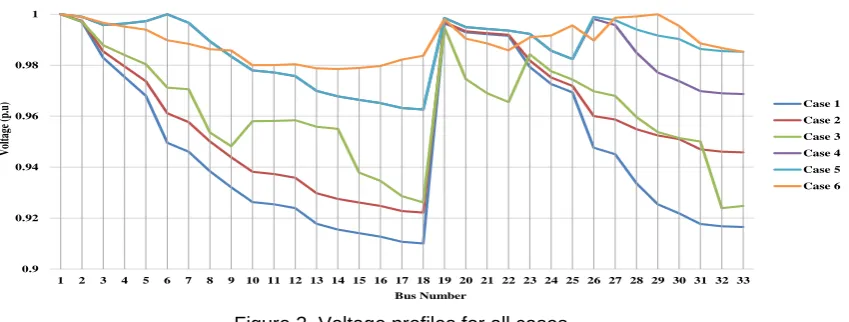
Figure 3 illustrates voltage profiles for all cases. All cases give better voltage profiles as compared to Case 1 (base case). Also, all the value of voltages at each bus is within the limit. For Case 2 and 3, there are no significant improvement can be obtained compare to the case 1 due to no active power injection to the system that can contribute better voltage improvement. This can showed in case 4 where injection of active power from the DG give better voltage profile at almost all buses when compare to case 1, 2 and 3. Furthermore, combination the DG and capacitor gives much better voltage profiles compare to case 4. Ultimately, the combination approach between the NR, DG and capacitor gives better voltage profiles compared to other cases where the voltage at each bus ranging between 0.97 and 1.0 p.u.
Figure 3. Voltage profiles for all cases
Table 3 shows several comparisons with other methods that published in the literature. From [34] and [35], the location and size for DG and capacitor are pre-determined before performing NR process. Thus, it will lead the solutions trapped in a local minimum. Similarly, in [36], the NR is done first by using minimal spanning tree and after that, the GA will optimize the DG and capacitor based on the pre-determined value of NR. Overall, the proposed approach (Case 6) has shown better reduction in total power loss compared to other references.
5. Conclusion
This paper has presented a solution to solve the NR, DG and capacitor, simulataneouly. The coordination for all three approaches is done by using ABC method. The solution is compared with other case studies in term of power loss reduction and voltage profiles. The results showed that combination between NR, DG and capacitor (case 6) gives better results with 82.82% of power loss reduction as well as improvement of voltage profiles. Besides that, comparisons with other references showed promising results in improving the power loss reduction in the test system.
0.9 0.92 0.94 0.96 0.98 1
1 2 3 4 5 6 7 8 9 10 11 12 13 14 15 16 17 18 19 20 21 22 23 24 25 26 27 28 29 30 31 32 33
V
olt
ag
e
(p.
u)
Bus Number
Case 1 Case 2 Case 3 Case 4 Case 5 Case 6
Table 3. Comparison with other references
Approach Total Power Losses (kW)
Proposed (Case 6) 34.90
Minimal Spanning Tree + GA
[36]* 78.48
GA [34]** 48
Analytical approach [37] 55.53
GA [35]** 50.15
* Network reconfiguration is determined by using Minimal Spanning Tree, whereas DG and capacitor are determined by using GA
Acknowledgements
The authors would like to express their appreciation to the Universiti Teknologi Malaysia (UTM) for supporting this work via PAS grant (02K23)
References
[1] Feng X, Shen W, Dong C, Zeng J, Shi J, Wang D. Study on Fundamental Principles and Methodologies of Distribution Network Reconfiguration. TELKOMNIKA Indonesian Journal of Electrical Engineering. 2014; 12(3): 1695-1700.
[2] Merlin A, Back H. Search for a minimal-loss operating spanning tree configuration in an urban power distribution system. Proceedings of the 5th Power System Computation Conference (PSCC). 1975: 1–18.
[3] Shirmohammadi D, Hong HW. Reconfiguration of electric distribution networks for resistive line losses reduction. IEEE Transactions on Power Delivery. 1989; 4(2): 1492–1498.
[4] Bogdan E, Bertrand R, Raphael C, Olivier D, Wojciech B, Nouredine H. Radial network reconfiguration using genetic algorithm based on the matroid theory. IEEE Transactions on Power
Systems. 2008; 23(1): 186-195.
[5] Xiaoling J, Jianguo Z, Ying S, Kejun L, Boqin Z. Distribution network reconfiguration for load balancing using binary particle swarm optimization. International Conference on Power System
Technology (PowerCon). 2004; 1: 507-510.
[6] Mori H, Ogita Y. A parallel tabu search based method for reconfigurations of distribution systems. Power Engineering Society Summer Meeting. 2000; 1: 73-78.
[7] Ghorbani MA, Hosseinian SH, Vahidi B. Application of Ant Colony System algorithm to distribution networks reconfiguration for loss reduction. Optimization of Electrical and Electronic Equipment
(OPTIM). 2008: 269-273.
[8] Aman MM, Jasmon GB, Bakar AHA, Mokhlis H, Karimi M. Optimum shunt capacitor placement in distribution system-A review and comparative study. Renewable and Sustainable Energy Reviews.
2014; 30: 429-439.
[9] Singh SP, Rao AR. Optimal allocation of capacitors in distribution system using particle swarm optimization. International Journal of Electrical Power and Energy System. 2012; 43(1): 267-1275. [10] Srinivasa Rao R. Capacitor placement in radial distribution system for loss reduction using artificial
bee colony algorithm. International Journal of Electrical, computer, energetic, electronic and
communication engineering. 2010; 4(8): 1108-1112.
[11] Srinivasas Rao R, Narasimham SVL, Ramalinaraju M. Optimal capacitor placement in a radial distribution system using plant growth simulation algorithm. International Journal of Electrical Power & Energy Systems. 2011; 33(5): 1133-1139.
[12] Swarup KS. Genetic algorithm for optimal capacitor allocation in radial distribution systems.
Proceedings of the 6th WSEAS International Conference on Evolutionsry Computing. Lisbon. 2005:
152-159.
[13] Mohd NM, Jasrul JJ, Danvu N, Nur AJ, Goro F. Optimal capacitor placement and sizing via artificial bee colony. International Journal of Smart Grid and Clean Energy. 2014; 3(2): 200-206.
[14] Barker PP, De Mello RW. Determining the impact of distributed generation on power systems. I. Radial distribution systems. Power Engineering Society Summer Meeting. 2000; 3: 1645-1656. [15] Griffin T, Tomsovic K, Secrest D, Law A. Placement of dispersed generation systems for reduced
losses. Proceedings of the 33rd Annual Hawaii International Conference on System Sciences. 2000:9.
[16] Dasan SGB, Ramalakshmi SS, Kumudini Devi RP. Optimal siting and sizing of hybrid Distributed
Generation using EP. International Conference on Power Systems (ICPS). 2009:1-6.
[17] Lalitha MP, Reddy VCV, Usha V. optimal DG placement for minimum real power loss in radial distribution systems using PSO. Journal of Theoretical and Applied Information Technology. 2010; 13(2):107-116.
[18] Abu-Mouti FS, El-Hawary ME.Optimal Distributed Generation Allocation and Sizing in Distribution Systems via Artificial Bee Colony Algorithm. IEEE Transactions on Power Delivery. 2011; 26 (4): 2090-2101.
[19] Pisica I, Bulac C, Eremia M. Optimal Distributed Generation Location and Sizing Using Genetic Algorithms. International Conference on Intelligent System Applications to Power Systems (ISAP). 2009:1-6.
[20] Sulaiman MH, Mustafa MW, Azmi A, Aliman O, Abdul Rahim SR. Optimal allocation and sizing of
Distributed Generation in distribution system via Firefly Algorithm. Power Engineering and
Optimization Conference (PEOCO). 2012: 84-89.
[22] Mohsen K, Rahman D, Reza D. Combination of Network Reconfiguration and Capacitor Placement for Loss Reduction in Distribution System with Based Genetic Algorithm. Proceedings of the 41st International Universities Power Engineering Conference. 2006: 308-312.
[23] Chung-Fu C. Reconfiguration and Capacitor Placement for Loss Reduction of Distribution Systems by Ant Colony Search Algorithm. IEEE Transactions on Power Systems. 2008; 23 (4): 1747-1755. [24] Gopiya SN, Khatod DK, Sharma MP.Optimal allocation of combined DG and capacitor for real power
loss minimization in distribution networks. International Journal of Electrical Power & Energy
Systems. 2013; 53: 967-973.
[25] Aman MM, Jasmon GB, Solngi KH, Bakar AHA, Mokhlis H. Optimum Simultaneous DG and capacitor on the Basic of Minimization of Power Losses. International Journal of Computer and Electrical Engineering. 2013; 5: 516-522.
[26] Esmailnezhad B, Shayeghi H. Simultaneous Distribution Network Reconfiguration and DG allocation for loss reduction by Invasive Weed Optimization algorithm. Conference on Smart Electric Grids Conference (SEGT).2012: 166-172.
[27] Imran AM, Kowsalya M, Kothari DP. A novel integration technique for optimal network reconfiguration and distributed generation placement in power distribution networks. International Journal of Electrical Power & Energy Systems. 2014; 63: 461-472.
[28] Lantharthong T, Rugthaicharoencheep N .Network Reconfiguration for Load Balancing in Distribution System with Distributed Generation and Capacitor Placement. International journal of electrical,
computer, energetic, electronic and communication engineering. 2012; 6(4): 409-414.
[29] Davar E, Kazem Z, Behnam MI, Sayyad N. Simultaneous Optimal Network Reconfiguration, DG and Fixed/Switched Capacitor Banks Placement in Distribution Systems using Dedicated Genetic Algorithm. Majlesi Journal of Electrical Engineering. 2015; 9(4): 31-41.
[30] Balakrishna G, Ch SB. Particle Swarm Optimization based Network Reconfiguration in Distribution System with Distributed Generation and Capacitor Placement. The international Journal of Engineering and science. 2014; 3(12): 55-60.
[31] Kang SL, Zong WG. A new meta-heuristic algorithm for continuous engineering optimization: harmony search theory and practice. Computer Methods in Applied Mechanics and Engineering. 2005; 194 (36-38): 3902-3933.
[32] Karaboga D. An idea on Honey bee swarm for numerical optimization. Erciyes University. Report number: 6. 2005.
[33] Baran ME, Wu FF. Network reconfiguration in distribution systems for loss reduction and load balancing. IEEE Transactions on Power Delivery. 1989; 4(2): 1401-1407.
[34] Rugthaicharoencheep N, Nedphograw, Wanaratwijit W. Distribution system operation for power loss minimization and improved voltage profile with distributed generation and capacitor placements.
International Conference on Electric Utility Deregulation and Restructuring and Power Technologies (DRPT).2011: 1185-1189.
[35] Saonerkar AK, Bagde BY. Optimized DG placement in radial distribution system with reconfiguration
and capacitor placement using genetic algorithm. International Conference on Advanced
Communication Control and Computing Technologies (ICACCCT). 2014: 1077-1083.
[36] Montoya DP, Ramirez JM. A joint optimization solution for reconfiguration, capacitor, and DG allocation in distribution systems. Transmission & Distribution Conference and Exposition - Latin America (PES T&D-LA). 2014:1-6.