DEVELOPMENT AND SUBSTANTIATION OF DYNAMIC
MECHANICAL MODEL OF NPP STRUCTURES FOUNDATION
REPRESENTED AS INERTIAL HOMOGENEOUS HALF-SPACE IN 3D
PROBLEM DEFENITION
Akop E. Sargsyan1, Elena G. Gukova2, Andrey S. Grishin3
1
Professor, Head of Dept. of Dynamics and Seismic Stability, JSC Atomenergoproekt, Moscow, Russia ([email protected])
2
Leading Scientist, Dept. of Dynamics and Seismic Stability, JSC Atomenergoproekt, Moscow, Russia
3
Chief Scientist, Dept. of Dynamics and Seismic Stability, JSC Atomenergoproekt, Moscow, Russia
ABSTRACT
Contemporary engineering methods for dynamic analyses of soil-structure systems are based on assumption that basemat is considered as a rigid body with 6 DOF. It is obvious that this assumption doesn’t allow us to evaluate internal forces in basemat. However, internal forces in basemat’s cross-sections are required for validation of the design. Therefore, the hypothesis that basemat is absolutely rigid is not acceptable in this case. In this paper the new mathematical model of soil-structure is developed that takes into account the finite stiffness of basemat.
INTRODUCTION
Foundation is the key component of a structure. The determination of internal forces in foundation’s cross-sections, with subsequent strength substantiation, is one of underlying requirements of structural engineering.
In Sargsyan (2008), Energia (1976), a submodel of soil foundation is a part of the main mathematical soil-structure model. The submodel of soil foundation is usually represented as six pairs of springs and dashpots, connected in parallel and characterizing stiffness of soil foundation, affected by integral resulting forces (three forces along coordinates and three moments relative to Cartesian coordinate system axes). Here, coordinate origin shall be placed in the center of gravity of the base of the foundation. Horizontal “x” and “y” axes are directed towards the basemat’s main inertia axes, with “z“, directing upwards from the base. Upper ends of all the six pairs of springs and dashpots, connected in parallel, are fastened in the center of gravity of the basemat, lower ends are fixed.
It’s assumed that parameters of mathematical model of soil foundation are to simulate reactions of the massless rigid foundation at unit translations and velocities (linear and angular) along and about the global coordinate axes. However, equivalent damping coefficients depend on mass and moment of inertia of a structure at torsion motion (ASCE 4-98).
In consideration of the above-mentioned, the necessity of the development of a new mechanical model of soil-structure is needed.
MECHANICAL SOIL-STRUCTURE MODEL
With a general structure motion as a result of Structure-Foundation Interaction, six resulting forces (three resulting forces Rx, Ry, Rz along axes x,y,z and three resulting moments
z R , y R , x
Asymptotic equations of the resulting forces are determined according to Sargsyan (2008), Energia (1976) by correlations as follows:
, c k
R ; u c u k R
; c k
R ; u c u k R
; c k
R ; u c u k R
z z z z z z
z z z z
y y y y y y
y y y y
x x x x x x
x x x x
(1)
where ux, uy, uz, x, y, z are linear and angular displacements along and relative to coordinate axes of the base of the foundation due to soil deformation; uy, uy, uz, x, y, z are linear and angular velocities of relative displacements of the base of the foundation along and about coordinate axes due to soil deformation; kx, ky, kz, kx, ky, kz are equivalent spring constants of soil foundation at linear and angular motions of a structure relative to coordinate axes; cx, cy, cz, cx, cy, cz are equivalent damping coefficients of soil foundation at linear and angular motions of a structure relative to coordinate axes.
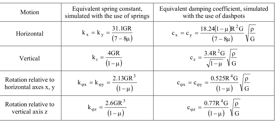
Soil spring and dashpot constants for circular foundations placed on a linearly deformable half-space are given in Table 1.
Table 1: Lumped Representation of Structure-Foundation Interaction at Surface for Circular Base.
Motion Equivalent spring constant, simulated with the use of springs
Equivalent damping coefficient, simulated with the use of dashpots
Horizontal
8 7
GR 1 . 31 k
kx y
7 8
GG R 1 24 . 18 c c
2 y
x
Vertical
1 GR 4 kz
G 1
G R 4 . 3 c
2 z
Rotation relative to
horizontal axes x, y
1
GR 13 . 2 k k3 y
x
1
GG R 525 . 0 c c
4 y
x
Rotation relative to
vertical axis z
1
GR 6 . 2 k
3 z
1
GG R 77 . 0 c
4 z
The following conventional signs are introduced in the table: is Poisson’s ratio of foundation medium; G is shear modulus of foundation medium; – density of foundation medium; R is radius of circular basemat.
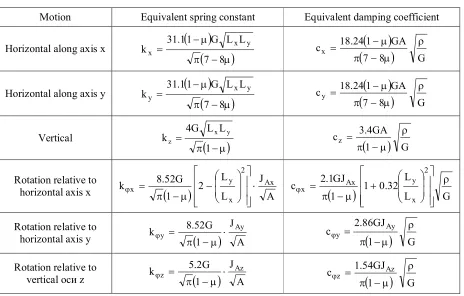
Table 2: Lumped Representation of Structure-Foundation Interaction at Surface for Rectangular Base.
Motion Equivalent spring constant Equivalent damping coefficient
Horizontal along axis x
8 7 L L G 1 1 . 31kx x y
7 8
GGA 1
24 . 18
cx
Horizontal along axis y
8 7 L L G 1 1 . 31ky x y
7 8
GGA 1
24 . 18
cy
Vertical
1 L L G 4kz x y
1
G GA 4 . 3cz
Rotation relative to
horizontal axis x
AJ L L 2 1 G 52 . 8 k Ax 2 x y x
L GL 32 . 0 1 1 GJ 1 . 2 c 2 x y Ax x
Rotation relative to
horizontal axis y
AJ 1 G 52 . 8
k y Ay
1
G GJ 86 . 2c y Ay
Rotation relative to
vertical оси z
AJ 1 G 2 . 5
k z Az
1
G GJ 54 . 1c z Az
The following additional conventional signs are used in Table 2:
) L L ( L ,
Lx y x y are length and width of basemat in directions of x and y, respectively;
y xL
L
A is area of the base of the foundation; JAx LxL3y/12, JAy LyL3x /12, JAz JAx JAy – moments of inertia of structure and basemat relative to principal central axes of inertia x, y and z, passing through the center of gravity of the base of the foundation.
SUBSTANTIATION OF THE DEVELOPED SOIL-STRUCTURE MODEL
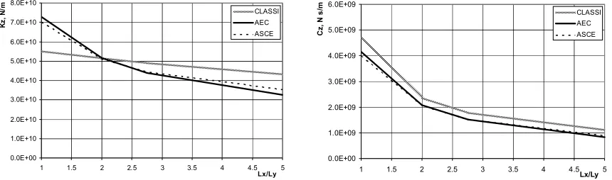
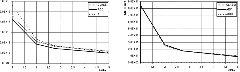
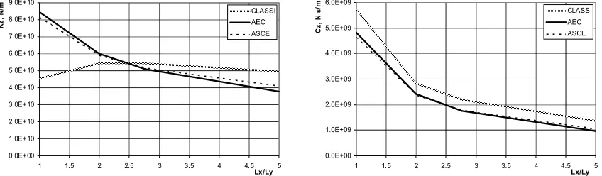
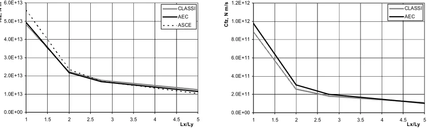
Verification of the expressions for soil spring and dashpot constants, given in Tables 1 and 2, is presented in Figures 1-12. The comparison is performed with the use of computer system CLASSI (graphs are marked with CLASSI) and ASCE 4-98 (graphs are marked with ASCE). All graphs (Figures 1-12) are calculated for the variation of basemat’s dimensions at two values of Poisson’s ratio of foundation medium 0.35 and 0.44. Calculations were done with the use of inputs as follows:
m 8 . 51
0.0E+00 1.0E+10 2.0E+10 3.0E+10 4.0E+10 5.0E+10 6.0E+10 7.0E+10
1 1.5 2 2.5 3 3.5 4 4.5 5
Lx/Ly
K
x
,
N
/m CLASSI
АЕС ASCE
0.0E+00 5.0E+08 1.0E+09 1.5E+09 2.0E+09 2.5E+09 3.0E+09
1 1.5 2 2.5 3 3.5 4 4.5 5
Lx/Ly
C
x
,
N
s
/m CLASSI
АЕС ASCE
Figure 1. Equivalent spring constant (on the left) and equivalent damping coefficient (on the right) of massless rigid foundation as a function of Lx/Ly along axis x at soil Poisson’s ratio µ = 0.35.
0.0E+00 1.0E+10 2.0E+10 3.0E+10 4.0E+10 5.0E+10 6.0E+10 7.0E+10
1 1.5 2 2.5 3 3.5 4 4.5 5
Lx/Ly
K
y
,
N
/m
CLASSI АЕС ASCE
0.0E+00 5.0E+08 1.0E+09 1.5E+09 2.0E+09 2.5E+09 3.0E+09
1 1.5 2 2.5 3 3.5 4 4.5Lx/Ly5
C
y
, N
s
/m CLASSI
АЕС ASCE
Figure 2. Equivalent spring constant (on the left) and equivalent damping coefficient (on the right) of massless rigid foundation as a function of Lx/Ly along axis y at soil Poisson’s ratio µ = 0.35.
0.0E+00 1.0E+10 2.0E+10 3.0E+10 4.0E+10 5.0E+10 6.0E+10 7.0E+10 8.0E+10
1 1.5 2 2.5 3 3.5 4 4.5 5
Lx/Ly
K
z
,
N
/m CLASSI
АЕС ASCE
0.0E+00 1.0E+09 2.0E+09 3.0E+09 4.0E+09 5.0E+09 6.0E+09
1 1.5 2 2.5 3 3.5 4 4.5 5
Lx/Ly
C
z
,
N
s
/m
CLASSI АЕС ASCE
0.0E+00 5.0E+12 1.0E+13 1.5E+13 2.0E+13 2.5E+13 3.0E+13 3.5E+13 4.0E+13 4.5E+13
1 1.5 2 2.5 3 3.5 4 4.5 5
Lx/Ly
K
fx
,
N
m CLASSI
АЕС ASCE
0.0E+00 1.0E+11 2.0E+11 3.0E+11 4.0E+11 5.0E+11 6.0E+11 7.0E+11 8.0E+11 9.0E+11
1 1.5 2 2.5 3 3.5 4 4.5 5
Lx/Ly
C
fx
,
N
m
/s
CLASSI АЕС ASCE
Figure 4. Equivalent spring constant (on the left) and equivalent damping coefficient (on the right) of massless rigid foundation as a function of Lx/Ly relative to axis x at soil Poisson’s ratio µ = 0.35.
0.0E+00 5.0E+12 1.0E+13 1.5E+13 2.0E+13 2.5E+13 3.0E+13 3.5E+13 4.0E+13 4.5E+13
1 1.5 2 2.5 3 3.5 4 4.5 5
Lx/Ly
K
fy
,
N
m CLASSI
АЕС ASCE
0.0E+00 1.0E+11 2.0E+11 3.0E+11 4.0E+11 5.0E+11 6.0E+11 7.0E+11 8.0E+11 9.0E+11
1 1.5 2 2.5 3 3.5 4 4.5 5
Lx/Ly
C
fy
,
N
m
/s
CLASSI АЕС ASCE
Figure 5. Equivalent spring constant (on the left) and equivalent damping coefficient (on the right) of massless rigid foundation as a function of Lx/Ly relative to axis y at soil Poisson’s ratio µ = 0.35.
0.0E+00 1.0E+13 2.0E+13 3.0E+13 4.0E+13 5.0E+13 6.0E+13
1 1.5 2 2.5 3 3.5 4 4.5 5
Lx/Ly
K
fz
,
N
m CLASSI
АЕС ASCE
0.0E+00 1.0E+11 2.0E+11 3.0E+11 4.0E+11 5.0E+11 6.0E+11 7.0E+11 8.0E+11 9.0E+11
1 1.5 2 2.5 3 3.5 4 4.5 5
Lx/Ly
C
fz
,
N
m
/s
CLASSI АЕС ASCE
0.0E+00 1.0E+10 2.0E+10 3.0E+10 4.0E+10 5.0E+10 6.0E+10 7.0E+10
1 1.5 2 2.5 3 3.5 4 4.5 5
Lx/Ly
K
x
,
N
/m CLASSI
АЕС ASCE
0.0E+00 5.0E+08 1.0E+09 1.5E+09 2.0E+09 2.5E+09 3.0E+09
1 1.5 2 2.5 3 3.5 4 4.5 5
Lx/Ly
C
x
,
N
s
/m CLASSI
АЕС ASCE
Figure 7. Equivalent spring constant (on the left) and equivalent damping coefficient (on the right) of massless rigid foundation as a function of Lx/Ly along axis x at soil Poisson’s ratio µ = 0.44.
0.0E+00 1.0E+10 2.0E+10 3.0E+10 4.0E+10 5.0E+10 6.0E+10 7.0E+10
1 1.5 2 2.5 3 3.5 4 4.5 5
Lx/Ly
K
y
,
N
/m CLASSI
АЕС ASCE
0.0E+00 5.0E+08 1.0E+09 1.5E+09 2.0E+09 2.5E+09 3.0E+09
1 1.5 2 2.5 3 3.5 4 4.5 5
Lx/Ly
C
y
,
N
s
/m CLASSI
АЕС ASCE
Figure 8. Equivalent spring constant (on the left) and equivalent damping coefficient (on the right) of massless rigid foundation as a function of Lx/Ly along axis y at soil Poisson’s ratio µ = 0.44.
0.0E+00 1.0E+10 2.0E+10 3.0E+10 4.0E+10 5.0E+10 6.0E+10 7.0E+10 8.0E+10 9.0E+10
1 1.5 2 2.5 3 3.5 4 4.5 5
Lx/Ly
K
z
,
N
/m CLASSI
АЕС ASCE
0.0E+00 1.0E+09 2.0E+09 3.0E+09 4.0E+09 5.0E+09 6.0E+09
1 1.5 2 2.5 3 3.5 4 4.5 5
Lx/Ly
C
z
,
N
s
/m CLASSI
АЕС ASCE
0.0E+00 1.0E+13 2.0E+13 3.0E+13 4.0E+13 5.0E+13 6.0E+13
1 1.5 2 2.5 3 3.5 4 4.5 5
Lx/Ly
K
fx
,
N
m CLASSI
АЕС ASCE
0.0E+00 2.0E+11 4.0E+11 6.0E+11 8.0E+11 1.0E+12 1.2E+12
1 1.5 2 2.5 3 3.5 4 4.5 5
Lx/Ly
C
fx
,
N
m
/s
CLASSI АЕС ASCE
Figure 10. Equivalent spring constant (on the left) and equivalent damping coefficient (on the right) of massless rigid foundation as a function of Lx/Ly relative to axis x at soil Poisson’s ratio µ = 0.44.
0.0E+00 1.0E+13 2.0E+13 3.0E+13 4.0E+13 5.0E+13 6.0E+13
1 1.5 2 2.5 3 3.5 4 4.5 5
Lx/Ly
K
fy
,
N
m CLASSI
АЕС ASCE
0.0E+00 2.0E+11 4.0E+11 6.0E+11 8.0E+11 1.0E+12 1.2E+12
1 1.5 2 2.5 3 3.5 4 4.5 5
Lx/Ly
C
fy
,
N
m
/s
CLASSI АЕС ASCE
Figure 11. Equivalent spring constant (on the left) and equivalent damping coefficient (on the right) of massless rigid foundation as a function of Lx/Ly relative to axis y at soil Poisson’s ratio µ = 0.44.
0.0E+00 1.0E+13 2.0E+13 3.0E+13 4.0E+13 5.0E+13 6.0E+13
1 1.5 2 2.5 3 3.5 4 4.5 5
Lx/Ly
K
fz
,
N
m CLASSI
АЕС ASCE
0.0E+00 2.0E+11 4.0E+11 6.0E+11 8.0E+11 1.0E+12 1.2E+12
1 1.5 2 2.5 3 3.5 4 4.5 5
Lx/Ly
C
fz
,
N
m
/s
CLASSI АЕС
Figure 12. Equivalent spring constant (on the left) and equivalent damping coefficient (on the right) of massless rigid foundation as a function of Lx/Ly relative to axis z at soil Poisson’s ratio µ = 0.44.
DISTRIBUTION OF SOIL SPRINGS AND DASHPOTS OVER THE BASE OF THE FOUNDATION
.
t
x
t
y
t
u
A
c
t
x
t
y
t
u
k
y
,
x
D
t
,
y
,
x
;
t
x
t
u
A
c
t
x
t
u
k
y
,
x
D
t
,
y
,
x
;
t
y
t
u
A
c
t
y
t
u
k
y
,
x
D
t
,
y
,
x
y x z z y x z z z zz z y x z y y z zy z x x z x x z zx
(2)Contact stresses distribution depend on the shape of foundation. For rectangular contact surface Lx×Ly, Dz
x,y
function is expressed under Sargsyan (2008), Energia (1976), Seymov (1976), Seymovet al. (1983), Gorbunov-Posadov et al. (1984) as follows:
, L y 2 1 L x 2 1 A 475 . 0 y , x D 2 y 2 x z (3)whereas for continuous circle base of radius R, the following equation will be true:
. R y x 1 R 5 . 0 y , x D 2 2 2 2 z (4)For rigid rectangular base, infinite along axis y, Dz
x,y
function is expressed as:
. L x 2 1 L 64 . 0 y , x D 2 x x z (5)Applied calculations involve the determination of internal forces, arising in foundation. While incorporating foundation finite stiffness with the use of FE method, one should determine the law of distribution of equivalent spring constants and damping coefficients of soil foundation over the base of the foundation.
To describe the structure spatial motion and incorporate finite stiffness of foundation, three pairs of springs and dashpots, connected in parallel, are fixed in FE model nodal points on basemat. Horizontal axes x and y of springs and dashpots are directed towards the structure base inertia principal axes, and axis z –upwards from the base of the foundation. The coordinate system origin is placed in the center of gravity of the foundation base. Upper ends of all the three pairs of springs and dashpots, connected in parallel, are fastened in the structure base FE model nodal points, lower ends being fixed.
data, available as of the date, see, for example, Sargsyan (2008), Energia (1976), CLASSI. Here, the data as above are sufficient to assume uniform distribution of contact stresses due to dashpot component in the base of foundation, as well as distribution of contact stresses due to spring component in span areas according to hyperbolic law; in structure base edge areas, they go towards finite extreme values:
- for circular base:
. R y x 0 with R
c , c c A c , c c
; R y x 0 with
R y x 1 R
k , k k A 5 . 0 k
, k k
2 2 2
z y x y , x z y x
2 2
2 R
2 2 2
z y x y , x z
y x
(6)
- for rectangular base:
,
L y 2 1
L x 2 1
L L
k , k k A k
, k k
2
y y 2
x x y
x
z y x y , x z
y x
(7)
where 0 x 0.5Lx, 0 y 0.5Ly, cx
cy,cz
Ax,y cx
cy,cz
/(Lx Ly), Ax,y is area of foundation base, correlated to a nodal point with coordinates x and y;N / y L y ; N / x L x ; N / 2 R
R
– mean value of the finite element size of circular base along radial direction - wise (for rectangular-base foundations – the same size along principal inertia axis x and y); N – number of finite elements of basemat; kx,ky,kz – integral equivalent spring constants, determined as per Tables 1 or 2, depending on foundation shape, along coordinate axes x, y, z;
z c , y c , x
c – integral equivalent damping coefficients, determined as per Tables 1 or 2, depending on
foundation shape, along coordinate axes x, y, z: kx,ky,kz – rigidity of springs, installed in nodal points with coordinates x, y, along coordinate axes x, y, z; cx,cy,cz – equivalent damping coefficients of dashpots, installed in nodal points with coordinates x, y, along coordinate axes x, y, z.
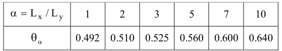
Summarizing results in Sargsyan (2008), ASCE 4-98, Seymov (1976), Seymov et al. (1983), Gorbunov-Posadov et al. (1984), the tabulated numerical values for coefficient are shown in Table 3.
Table 3: Dependence of on Lx/Ly.
y x/L
L
1 2 3 5 7 10
0.492 0.510 0.525 0.560 0.600 0.640
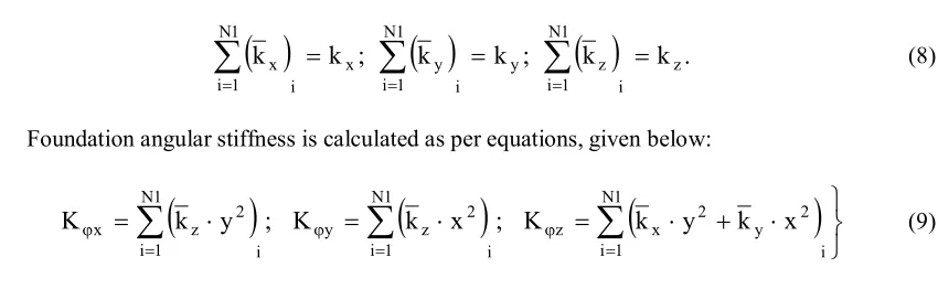
k k ;
k k ;
k kz.i 1 N
1 i
z y
i 1 N
1 i
y x
i 1 N
1 i
x
(8)
Foundation angular stiffness is calculated as per equations, given below:
i 1
N
1 i
2 y 2 x z
i 1
N
1 i
2 z y
i 1
N
1 i
2 z
x k y ; K k x ; K k y k x
K (9)
The following additional conventional signs are adopted in (8) and (9): i=1,…,N1 – N. of node of FE model of basemat; x, y – coordinates of a nodal points, numbered as “i“.
The comparison between contact stresses, arising in certain points of rectangular-base foundations, as percentage of average pressure, produced by vertical force, in accordance with the accepted distribution law, and contact stress values, obtained in Seymov(1976), for y= 0 is resented in Table 4.
Table 4: Contact stresses comparison in percentage of average pressure.
2x/Lx 0.0 0.2 0.4 0.6 0.8 0.9 0.95
As per [6] 0.47500 0.48500 0.51800 0.59200 0.78500 1.07600 1.50400 AES 0.47500 0.48500 0.51800 0.59375 0.79170 1.08970 1.52100
CONCLUSION
The new mechanical soil-structure model is developed. The model can be applied for both rigid and deformable foundations. It is shown that equivalent spring constants and damping coefficients of the developed model are well harmonized with current standards. To be able to calculate internal forces in foundations a new distribution law of springs and dashpots over the base of the foundation is introduced.
REFERENCES
Computer system CLASSI. Determination of dynamic rigidity of rigid foundation of arbitrary shape. UCSD, USA.
Dynamics of continuous media in calculations for hydraulic structures. (1976). Energia, Moscow, Russia. Gorbunov-Posadov, M. I., Malokova, T. A., Solomin, V. I. (1984). “Calculation of elastic-base
structures”, Striyizdat, Moscow, Russia.
Sargsyan, A. E. (2008). “Structural mechanics”, Vysshaya shkola, Moscow, Russia. Seismic Analysis of Safety Related Nuclear Structures. Approved September, ASCE. Seymov, V. M. (1976). “Dynamic contact problems”, Naukova dumka, Kiev, Ukraine.
Seymov, V. M., Ostroverkh, B. N., Ermolenko, A. I. (1983). “Dynamics and seismic stability of hydraulic structures”, Naukova dumka, Kiev, Ukraine.