University of Windsor University of Windsor
Scholarship at UWindsor
Scholarship at UWindsor
Electronic Theses and Dissertations Theses, Dissertations, and Major Papers
2016
CLEAN COMBUSTION CONTROL IN A COMPRESSION IGNITION
CLEAN COMBUSTION CONTROL IN A COMPRESSION IGNITION
ENGINE
ENGINE
Prasad Sajjan Divekar University of Windsor
Follow this and additional works at: https://scholar.uwindsor.ca/etd
Recommended Citation Recommended Citation
Divekar, Prasad Sajjan, "CLEAN COMBUSTION CONTROL IN A COMPRESSION IGNITION ENGINE" (2016). Electronic Theses and Dissertations. 5813.
https://scholar.uwindsor.ca/etd/5813
This online database contains the full-text of PhD dissertations and Masters’ theses of University of Windsor students from 1954 forward. These documents are made available for personal study and research purposes only, in accordance with the Canadian Copyright Act and the Creative Commons license—CC BY-NC-ND (Attribution, Non-Commercial, No Derivative Works). Under this license, works must always be attributed to the copyright holder (original author), cannot be used for any commercial purposes, and may not be altered. Any other use would require the permission of the copyright holder. Students may inquire about withdrawing their dissertation and/or thesis from this database. For additional inquiries, please contact the repository administrator via email
CLEAN COMBUSTION CONTROL IN A COMPRESSION IGNITION ENGINE
by
Prasad Sajjan Divekar
A Dissertation
Submitted to the Faculty of Graduate Studies
through the Department of Mechanical, Automotive and Materials Engineering
in Partial Fulfillment of the Requirements for
the Degree of Doctor of Philosophy
at the University of Windsor
Windsor, Ontario, Canada
2016
CLEAN COMBUSTION CONTROL IN A COMPRESSION IGNITION
ENGINE
by
Prasad Sajjan Divekar
APPROVED BY:
______________________________________________ Dr. C. R. Koch, External Examiner
Department of Mechanical Engineering, University of Alberta
______________________________________________ Dr. X. Xu, Outside Reader
Department of Civil and Environmental Engineering
______________________________________________ Dr. D. Ting, Programme Reader
Department of Mechanical, Automotive and Materials Engineering
______________________________________________ Dr. J. Tjong, Programme Reader
Department of Mechanical, Automotive and Materials Engineering
______________________________________________ Dr. M. Zheng, Co-advisor
Department of Mechanical, Automotive and Materials Engineering
______________________________________________ Dr. X. Chen, Co-advisor
Department of Electrical and Computer Engineering
DECLARATION OF ORIGINALITY
I hereby certify that I am the sole author of this dissertation and that the framework and
the details of the technical core of the dissertation have not been published. The proof of
the majority of findings has mostly been refereed and produced to original research
publications in journals and professional conferences with myself being the first author.
I certify that, to the best of my knowledge, my dissertation does not infringe upon
anyone’s copyright nor violate any proprietary rights and that any ideas, techniques,
quotations, or any other material from the work of other people included in my thesis,
published or otherwise, are fully acknowledged in accordance with the standard
referencing practices. Furthermore, to the extent that I have included copyrighted material
that surpasses the bounds of fair dealing within the meaning of the Canada Copyright
Act, I certify that I have obtained a written permission from the copyright owner(s) to
include such material(s) in my dissertation and have included copies of such copyright
clearances to my appendix.
I declare that this is a true copy of my dissertation, including any final revisions, as
approved by my dissertation committee and the Graduate Studies office, and that this
dissertation has not been submitted for a higher degree to any other University or
ABSTRACT
The primary objective of this dissertation is to develop combustion control strategies, that
can reduce the thermal efficiency penalty associated with clean combustion in modern
compression ignition engines. The clean combustion targets of simultaneously low oxides
of nitrogen (NOX) and smoke emissions are selected as the platforms for demonstrating
the dynamic control strategies on a single cylinder research engine.
First, parametric analyses, including exhaust gas recirculation (EGR) calculations, are
performed using a zero-dimensional engine cycle simulation model. Thereafter, two
combustion strategies are experimentally investigated, namely the single-shot diesel
strategy and the dual-fuel strategy. The single-shot diesel combustion strategy employs a
single direct injection of diesel with the use of moderate levels of EGR. In the dual-fuel
combustion strategy, port injection of ethanol is utilized in addition to the direct injection
of diesel and the application of EGR. The results of parametric analyses and engine
experiments provide guidelines for the development of a systematic control strategy.
Closed-loop combustion control systems are implemented for regulating the fuel injection
commands, by which the combustion phasing is effectively controlled on a
cycle-by-cycle basis in both the diesel and dual-fuel combustion strategies. The fuel injection
control is integrated into the systematic control strategy for simultaneously controlling
the air and fuel systems. The intake boost pressures, EGR rates, and fuelling strategies are
dynamically selected, depending on the engine load level. By implementing the
systematic control, both the NOX and smoke targets are achieved over a wide engine load
DEDICATION
This dissertation is dedicated to my parents,
Sajjan Bhimrao Divekar
and
ACKNOWLEDGEMENTS
With great pleasure, I take the opportunity to thank my advisors, Prof. Ming Zheng, and
Prof. Xiang Chen for the inspiration, guidance, and encouragement I received from them
throughout the Ph.D. program. The regular and excellent feedback on my work has
helped me in developing critical thinking and a technical ability that will stay with me
throughout my career. I would also like to express my gratitude towards my committee
members, Dr. David Ting, Dr. Jimi Tjong, and Dr. Xiaohong (Iris) Xu for their valuable
guidance in this research. Special thanks to the external examiner, Professor C.R. Koch
from University of Alberta, for his helpful suggestions for improving the quality of my
Ph.D. dissertation.
I would like to acknowledge the support I received from my colleagues at the Clean
Combustion Engine Laboratory. Dr. Meiping Wang, Dr. Usman Asad, Dr. Xiaoye Han,
Qingyuan Tan, Dr. Shui Yu, Dr. Tadanori Yanai, Dr. Xiao Yu, Kelvin Xie, Tongyang
Gao, Marko Jeftic, Zhenyi Yang, Shouvik Dev, Geraint Bryden, Chris Aversa, and Mark
Ives are thanked for their invaluable assistance in my research. Additionally, I would like
to thank the lab members for proof-reading the dissertation and for their constructive
criticism. Special thanks to Bruce Durfy, who has helped immensely in the fabrication of
the components used in the experimental setup at the laboratory. Many thanks to the staff
at the MAME department and at the office of Graduate Studies for handling the
paperwork related to my assistantships and for arranging the external examiner.
I am also grateful for the support from the University of Windsor, AUTO21, the Canada
Natural Sciences and Engineering Research Council of Canada for the research support. I
would also like to acknowledge the Ford Motor Company, and in particular Dr. Jimi
Tjong for allowing me to work at the PERDC, Windsor facility where I gained invaluable
industry experience.
Finally, but not the least, I would like to thank my wife, Madalina, for understanding my
commitments as a Ph.D. student and for her love and patience.
Prasad Sajjan Divekar
Windsor, Ontario
Canada
TABLE OF CONTENTS
DECLARATION OF ORIGINALITY ... iii
ABSTRACT ... iv
DEDICATION ...v
ACKNOWLEDGEMENTS ... vi
LIST OF TABLES ... xiii
LIST OF FIGURES ... xiv
NOMENCLATURE ... xix
1. INTRODUCTION ...1
1.1. The Compression Ignition Engine ...1
1.2. Emission and Efficiency Regulations...3
1.3. CI Engine Control Systems ...6
1.4. Engine Calibration and Control Design ...10
1.5. Scope of Work ...12
1.6. Dissertation Significance ...12
1.7. Dissertation Outline ...13
2. LITERATURE REVIEW ...16
2.1. Diesel Low Temperature Combustion ...16
2.2. Combustion of Alternative Fuels in Compression Ignition Engines ...20
2.3. Opportunities for Control of Clean Combustion in CI Engines ...24
3. RESEARCH METHODOLOGY ...26
3.1. Research Targets ...26
3.3. Experimental Setup ...30
3.3.1. Test Engine ...30
3.3.2. Intake Boost and EGR System ...32
3.3.3. Fuel Systems ...34
3.3.4. Emission Analyzers ...36
3.4. Test Management ...39
3.4.1. Air System Management and Data Acquisition...39
3.4.2. Cylinder Pressure Measurement and Analysis ...40
3.4.3. Fuel System Control ...42
4. PARAMETRIC ANALYSIS ...46
4.1. EGR Analysis ...46
4.1.1. Analytical Approach ...47
4.1.2. Air-fuel Ratio Considerations ...50
4.1.3. Extension to Dual-fuel Combustion...51
4.2. In-cylinder Processes ...52
4.3. Results of Parametric Analysis...55
4.3.1. Interactions Among Intake Boost, EGR, and Fuelling Amount ...55
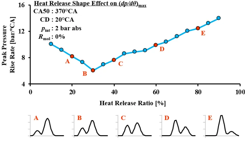
4.3.2. Impact of Heat Release Patterns ...57
4.3.3. Combustion Efficiency Effect...62
4.4. Summary of Parametric Analysis ...64
5. TESTING OF DIESEL AND DUAL-FUEL COMBUSTION ...65
5.1. Single-shot Diesel Combustion at Low Engine Load ...66
5.1.2. Application of EGR with Fuel Injection Timing Adjustments ...71
5.2. Clean Combustion with Single Diesel Injection at Increased Load ...74
5.2.1. Impact of EGR and Combustion Phasing at 10 bar IMEP...74
5.2.2. Engine Load Limit for Single-shot Diesel Combustion ...77
5.3. Diesel-ethanol Dual-fuel Combustion ...79
5.3.1. Effect of Ethanol-to-diesel Ratio on DFC ...79
5.3.2. Dual-fuel Combustion at Low Engine Load ...85
5.3.3. Load Extension with Dual-fuel Combustion ...88
5.4. Summary of Diesel and Dual-fuel Combustion Tests ...92
6. CLOSED-LOOP COMBUSTION CONTROL ...94
6.1. Cycle-by-cycle Cylinder Pressure Analysis ...95
6.1.1. Cylinder Pressure Acquisition ...95
6.1.2. Real-time Heat Release Analysis ...97
6.2. Closed-loop Control of Diesel Injection ...99
6.2.1. CA50 Control ...99
6.2.2. IMEP Control ...101
6.3. Test Results with Closed-loop Combustion Control ...104
6.3.1. Step Response of IMEP and CA50 Control ...104
6.3.2. Control Comparisons with SSDC EGR Sweeps ...107
6.3.3. Control Comparisons with DFC EGR Sweeps ...111
6.4. Summary of Closed-loop Combustion Control ...115
7. DESIGN AND DEMONSTRATION OF SYSTEMATIC CONTROL ...117
7.2. Dynamic Target for Air-path Control ...118
7.2.1. Intake O2 and NOX correlation ...118
7.2.2. In-cylinder Air Excess Ratio and Smoke Correlation...121
7.2.3. Air-path Control Considerations ...122
7.3. Dynamic Target for Combustion Control ...125
7.3.1. Preferred CA50 ...125
7.3.2. Diesel and Dual-fuel Combustion Switching ...126
7.4. Systematic Control Demonstration ...128
7.4.1. Switching between Diesel and Dual-fuel Combustion ...128
7.4.2. Load Sweep with Systematic Control ...132
7.5. Summary of Systematic Control ...136
8. CONCLUSIONS AND FUTURE WORK ...137
8.1. Numerical Analysis ...137
8.2. Steady-state Engine Tests ...138
8.3. Closed-loop Combustion Control ...139
8.4. Systematic Control ...140
8.5. Recommendations for Future Work ...141
REFERENCES ...142
APPENDICES ...157
APPENDIX A. CO2 Regulations and Thermal Efficiency...158
APPENDIX B. Properties of Commonly Used Fuels ...159
APPENDIX C. Equipment List ...161
APPENDIX E. Additional Test Results ...171
APPENDIX F. Diesel Injection Characterization ...176
APPENDIX G. Online Model Adaptation with Extremum Seeking...179
LIST OF PUBLICATIONS ...188
LIST OF TABLES
Table 1.1 Technology Integration Example for Cummins Engines ...4
Table 3.1 Test Engine Specifications...31
Table 3.2 Test Fuel Specifications ...36
Table 3.3 Intake and Exhaust Gas Analyzers ...37
Table 3.4 Summary of Data Acquisition Devices ...40
Table 5.1 Summary of SSDC Engine Load Extension Tests...78
Table 5.2 Summary of Dual-fuel Engine Load Extension Tests ...92
Table 6.1 Controller Settings for CA50 and IMEP Control ...103
Table 7.1 Steady-state Emissions: SSDC and DFC Mode Switching ...131
LIST OF FIGURES
Figure 1.1 US EPA Emission Regulations for Heavy-duty Diesel Engines ...3
Figure 1.2 US EPA CO2 Emission Standards for Heavy-duty Diesel Engines ...5
Figure 1.3 Classical Diesel Engine Control Layout...7
Figure 1.4 Modern Diesel Engine Control Layout ...9
Figure 1.5 Typical Engine Calibration and ECU Operation ...11
Figure 1.6 Dissertation Outline ...15
Figure 2.1 Diesel HTC versus LTC: Pressure and Heat Release ...17
Figure 2.2 Conceptual Representation of NOX and Smoke Formation ...18
Figure 2.3 Common Low Temperature Combustion Strategies with Diesel ...19
Figure 2.4 Energy Densities of Common Fuels and Energy Storage Devices ...21
Figure 2.5 Port Injection Suitability and Ignition Properties of Selected Fuels ...22
Figure 3.1 Schematic of Research Methodology ...29
Figure 3.2 Test Engine Setup ...33
Figure 3.3 Fuel System Schematic...34
Figure 3.4 Test Control and Data Synchronization ...39
Figure 3.5 Injection Control and Cylinder Pressure Feedback ...44
Figure 3.6 Hardware Connections for Injection Control ...45
Figure 4.1 Schematic Representation of EGR Molar Balance ...48
Figure 4.2 Effect of pint and IMEP on pmax and λin-cyl at 40% EGR ...56
Figure 4.3 Effect of EGR and IMEP on [O2]int and λin-cyl ...57
Figure 4.5 Illustration of Heat Release Duration Ratio ...60
Figure 4.6 Illustration of Heat Release Energy Ratio ...60
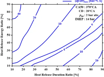
Figure 4.7 Heat Release Energy Ratio Effect on (dp/dθ)max ...61
Figure 4.8 Effect of Heat Release Shape on (dp/dθ)max ...62
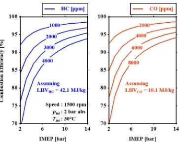
Figure 4.9 Combustion Efficiency Penalty from Exhaust HC and CO ...63
Figure 5.1 SSDC – EGR Sweep: NOX and Smoke ...66
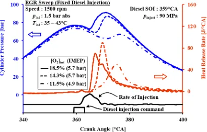
Figure 5.2 SSDC – EGR Sweep: Cylinder Pressure and AHRR ...67
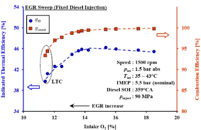
Figure 5.3 SSDC – EGR Sweep: ηth and ηcomb ...69
Figure 5.4 SSDC – EGR Sweep: HC and CO ...69
Figure 5.5 SSDC – EGR Sweep: CA50 and CD ...70
Figure 5.6 SSDC – EGR Sweep at Fixed CA50: ID and SOI ...72
Figure 5.7 SSDC – EGR Sweep at Fixed CA50: NOX and Smoke ...73
Figure 5.8 SSDC – EGR Sweep at Fixed CA50: ηth and ηcomb ...74
Figure 5.9 SSDC – EGR Sweeps at 10 bar IMEP: NOX and Smoke ...75
Figure 5.10 SSDC – EGR Sweeps at 10 bar IMEP: ηth and ηcomb ...76
Figure 5.11 SSDC: Impact of Load on NOX-smoke Trade-off ...78
Figure 5.12 DFC – Ethanol Fraction Effect: NOX and Smoke ...80
Figure 5.13 DFC – Ethanol Fraction Effect: Cylinder Pressure and AHRR ...81
Figure 5.14 DFC – Ethanol Fraction Effect: ηth and ηcomb ...82
Figure 5.15 DFC – Ethanol Fraction Effect: CO and HC ...83
Figure 5.16 DFC – Ethanol Fraction Effect: (dp/dθ)max and pmax ...84
Figure 5.18 DFC – EGR Effect at 4 bar IMEP: Smoke and NOX ...86
Figure 5.19 DFC – EGR Effect at 4 bar IMEP: Thermal Efficiency ...87
Figure 5.20 DFC – EGR Effect at 4 bar IMEP: CO and HC ...87
Figure 5.21 DFC – EGR Effect at Increased Load: Smoke and NOX ...89
Figure 5.22 DFC – EGR Effect at Increased Load: Thermal Efficiency ...89
Figure 5.23 DFC – EGR Effect at Increased Load: pmax and (dp/dθ)max ...90
Figure 5.24 Sample Pathway Towards Full-load Operation Under DFC ...91
Figure 6.1 Schematic of Cycle-by-cycle Cylinder Pressure Analysis ...96
Figure 6.2 Illustration of Real-time Heat Release Analysis ...98
Figure 6.3 SOI versus CA50 for SSDC and DFC ...100
Figure 6.4 Closed-loop CA50 Control Region for SSDC and DFC ...100
Figure 6.5 Proportional Controller for Closed-loop Control of CA50 ...101
Figure 6.6 Injected Fuel Amount versus Commanded Injection Duration ...102
Figure 6.7 Proportional Controller for Closed-loop Control of IMEP ...103
Figure 6.8 IMEP Setpoint Step-change: Closed-loop IMEP Control ...105
Figure 6.9 IMEP Setpoint Step-change: Diesel Injection Commands ...105
Figure 6.10 CA50 Setpoint Step-change: Closed-loop CA50 Control ...106
Figure 6.11 CA50 Setpoint Step-change: Diesel Injection Commands ...107
Figure 6.12 Control Comparison with SSDC EGR Sweeps: CA50 and IMEP ...108
Figure 6.13 Control Comparison with SSDC EGR Sweeps: Injection ...109
Figure 6.14 Control Comparison with SSDC EGR Sweeps: Smoke and NOX ...110
Figure 6.16 Control Comparison with DFC EGR Sweeps: CA50 and IMEP ...112
Figure 6.17 Control Comparison with DFC EGR Sweeps: Injection ...113
Figure 6.18 Control Comparison with DFC EGR Sweeps: Smoke and NOX ...114
Figure 6.19 Control Comparison with DFC EGR Sweeps: Stability...115
Figure 7.1 Systematic Control Architecture ...118
Figure 7.2 NOX versus Intake O2 Concentration for SSDC and DFC Strategies ...119
Figure 7.3 NOX Reduction for SSDC and DFC Strategies ...120
Figure 7.4 Effect of [O2]int and λin-cyl on Smoke Trends ...122
Figure 7.5 Contour Map of pint and MAF at Varying Loads and a Fixed [O2]int ...124
Figure 7.6 Region of CA50 for Thermal Efficiency and NOX Improvements...125
Figure 7.7 Thermal Efficiency versus IMEP for SSDC and DFC ...127
Figure 7.8 Combustion Efficiency versus IMEP for SSDC and DFC ...127
Figure 7.9 SSDC to DFC Switching: Injection Duration and IMEP ...129
Figure 7.10 SSDC to DFC Switching: CA50 and Diesel SOI ...129
Figure 7.11 DFC to SSDC Switching: Injection Duration and IMEP ...130
Figure 7.12 DFC to SSDC Switching: CA50 and Diesel SOI ...131
Figure 7.13 IMEP Sweep with Control: pint and MAF ...133
Figure 7.14 IMEP Sweep with Control: [O2]int and λin-cyl ...133
Figure 7.15 IMEP Sweep with Control: Smoke and NOX ...134
Figure 7.16 IMEP Sweep with Control: CA50 and Diesel SOI ...135
Figure 7.17 IMEP Sweep with Control: Diesel and Ethanol Injection Duration...135
Figure A.2 Schematic of Calculation Routine for Zero-D Simulations ...167
Figure A.3 Effect of Heat Release Shape on pmax ...170
Figure A.4 Effect of Heat Release Shape on ηth ...170
Figure A.5 NOX Measurements with Different Devices...171
Figure A.6 SSDC: Cylinder Pressure and AHRR (200 cycles) ...172
Figure A.7 SSDC: Cylinder Pressure and AHRR ...173
Figure A.8 DFC at 13.1 bar IMEP ...174
Figure A.9 DFC at 15.1 bar IMEP ...174
Figure A.10 DFC at 17.6 bar IMEP ...175
Figure A.11 DFC at 19.2 bar IMEP ...175
Figure A.12 Injector Characterization with EFS Bench ...176
Figure A.13 Opening Delay for Delphi Solenoid Injector ...177
Figure A.14 Closing Delay for Delphi Solenoid Injector ...178
Figure A.15 Injected Mass for Delphi Solenoid Injector ...178
Figure A.16 Structure of Online Model Parameter Calibration ...181
Figure A.17 Perturbation Based ES Structure Applied to Model Calibration ...182
Figure A.18 Online Fuel Correction to Improve Model Estimations ...185
Figure A.19 Model Estimation of Intake and Exhaust O2 Concentrations ...186
NOMENCLATURE
Acronyms
AHRR Apparent Heat Release Rate [J/°CA]
AI Analog Input [-]
AO Analog Output [-]
CA Crank Angle [°CA]
CA05 Crank Angle of 5% Heat Release [°CA]
CA50 Crank Angle of 50% Heat Release [°CA]
CA95 Crank Angle of 95% Heat Release [°CA]
CCEL Clean Combustion Engine Laboratory [-]
CD Combustion Duration [°CA]
CAN Controller Area Network [-]
CAI California Analytical Instruments [-]
CI Compression Ignition [-]
CN Cetane Number [-]
CO Carbon Monoxide [-]
COV Coefficient of Variation [%]
CR Compression Ratio [-]
DAQ Data Acquisition [-]
DIO Digital Input Output [-]
DI Direct-injection [-]
DIO Digital Input and Output [-]
DMA Direct Memory Access [-]
DOC Diesel Oxidation Catalyst [-]
DPF Diesel Particulate Filter [-]
ECU Engine Control Unit [-]
EGR Exhaust Gas Recirculation [-]
EOC End of Combustion [°CA]
EPA Environmental Protection Agency [-]
ES Extremum Seeking [-]
EVO Exhaust Valve Opening [°CA]
FFT Fast Fourier Transform [-]
FIFO First-in First-out [-]
FPGA Field Programmable Gate Array [-]
FSN Filter Smoke Number [FSN]
H2O Water [-]
HC Hydrocarbon [-]
HCCI Homogeneous Charge Compression Ignition [-]
HFID Heated Flame Ionization Detector [-]
HPP High-pressure Pump [-]
HTC High Temperature Combustion [-]
ID Ignition Delay [ms]
IMEP Indicated Mean Effective Pressure [bar]
IVC Intake Valve Closing [°CA]
LHV Lower Heating Value [MJ/kg]
LNT Lean NOX Trap [-]
LPP Low-pressure Pump [-]
LTC Low Temperature Combustion [-]
MAF Mass Air Flow [g/s]
MFB Mass Fraction Burnt [-]
MK Modulated Kinetics [-]
N2 Nitrogen [-]
NDIR Non-dispersive Infra-red [-]
NI National Instruments [-]
NO Nitric Oxide [-]
NO2 Nitrogen Dioxide [-]
NOX Oxides of Nitrogen [-]
O2 Oxygen Gas [-]
OS Operating System [-]
PCI Pre-mixed Compression Ignition [-]
PCV Pressure Control Valve [-]
PFI Port Fuel Injection [-]
PM Particulate Matter [-]
ppm Parts per Million by Volume [ppm]
PREDIC PREmixed Lean Diesel Combustion [-]
RCCI Reactivity Controlled Compression Ignition [-]
rpm Revolutions per Minute [rpm]
RT Real-time [-]
SCR Selective Catalytic Reduction [-]
SI Spark Ignition [-]
SOC Start of Combustion [°CA]
SOI Start of Injection [°CA]
SSDC Single-shot Diesel Combustion [-]
TDC Top Dead Centre [-]
TTL Transistor-transistor Logic [-]
TWC Three-way Catalytic Converter [-]
UNIBUS UNIform Bulky Combustion System [-]
US United States [-]
USB Universal Serial Bus [-]
VCV Volume Control Valve [-]
VGT Variable Geometry Turbocharger [-]
Symbols
𝐴s Combustion Chamber Surface Area [m2]
𝑎 Crank Radius [m]
𝐶1 Heat Transfer Model Parameter [-]
𝐶2 Heat Transfer Model Parameter [-]
𝐶𝑓 Fuel Molecular Composition Parameter [-]
𝐶1𝐻𝛽𝑂𝛾 Fuel Molecular Formula [-]
𝐶1𝐻𝛽1𝑂𝛾2 Fuel-A for Dual-fuel Consideration [-]
𝐶1𝐻𝛽2𝑂𝛾2 Fuel-B for Dual-fuel Consideration [-]
𝐶𝐷 Combustion Duration [ºCA]
𝐶𝐷
̅̅̅̅ Heat Release Duration Ratio [-]
𝐶𝐷1 Duration of First Stage of Combustion [°CA]
[CO2]int Intake CO2 Concentration [%]
[CO2]exh Exhaust CO2 Concentration [%]
(𝑑𝑝/𝑑𝜃)max Peak Pressure Rise Rate [bar/°CA]
HR
̅̅̅̅ Heat Release Energy Ratio [-]
𝐻𝑅1 Fuel Energy in First Stage Heat Release [J]
𝑙 Connecting Rod Length [m]
𝑚cyl Mass of Cylinder Charge [g/cycle]
𝑚egr Mass of Recirculated Exhaust Gases [g/cycle]
𝑛int Moles of Intake Charge [mol/cycle]
𝑛egr Moles of Recirculated Exhaust Gases [mol/cycle]
𝑛exh Moles of Exhaust Gases [mol/cycle]
𝑛f Moles of Fuel [mol/cycle]
𝑛f1 Moles of Fuel-A [mol/cycle]
𝑛f2 Moles of Fuel-B [mol/cycle]
𝑛O2 Intake Moles of O2 [mol/cycle]
𝑛CO2 Intake Moles of CO2 [mol/cycle]
𝑛H2O Intake Moles of H2O [mol/cycle]
𝑛N2 Intake Moles of N2 [mol/cycle]
[O2]air Ambient O2 Concentration [%]
[O2]int Intake O2 Concentration [%]
[O2]exh Exhaust O2 Concentration [%]
𝑝 Cylinder Pressure [bar]
𝑝inject Common-rail Fuel Injection Pressure [MPa]
𝑝int Intake Manifold Pressure [bar]
𝑝max Peak Cylinder Pressure [bar]
𝑄app Apparent Heat Release [J]
𝑄f Fuel Energy [J]
𝑄ht Heat Transfer [J]
𝑟CO2 CO2 EGR Ratio [-]
𝑟O2 O2 EGR Ratio [-]
𝑟mol Molar EGR Ratio [-]
𝑟mass Mass EGR ratio [-]
𝑆p Mean Piston Speed [m/s]
𝑇 Bulk Gas Temperature [K]
𝑇max Peak Cylinder Bulk Gas Temperature [K]
𝑇int Intake Manifold Temperature [°C]
𝑇wall Cylinder Wall Temperature [K]
𝑈 Internal Energy [J]
𝑉 Cylinder Volume [m3]
𝑉𝑐 Clearance Volume [m3]
𝑉𝑠 Swept Volume [m3]
𝑊 Piston Work [J]
𝜃𝑆𝑂𝐶 Crank Angle for Start of Combustion [°CA]
𝜃 Crank Angle [°CA]
𝜆air Fresh Air Excess Ratio [-]
𝜆in−cyl In-cylinder Air Excess Ratio [-]
𝜒 Port-injection Fuel Energy Ratio [-]
𝜒′ Port-injection Fuel Molar Ratio [-]
CHAPTER 1: INTRODUCTION
CHAPTER I
1. INTRODUCTION
Internal combustion (IC) engines currently remain the preferred choice among the
available powertrain options for automobiles [1], [2]. The IC engines typically burn
hydrocarbon fuels to produce mechanical work and the products of combustion are
exhausted to the atmosphere. The emission of toxic combustion products into the
atmosphere poses major health and environmental concerns [3]. Therefore, the exhaust
emissions, such as oxides of nitrogen (NOX), particulate matter (PM), unburnt
hydrocarbons (HC), and carbon monoxide (CO) are strictly regulated in North America
and other parts of the world [4]. In addition, carbon dioxide (CO2) regulations are in
place to address the climate change and energy security concerns [5].
1.1.The Compression Ignition Engine
The two common IC engine types are the compression ignition (CI) engine and the spark
ignition (SI) engine. When compared to the SI engines, the CI engines exhibit several
advantages. The higher geometric compression ratio (CR) and the fuel-lean operation of
the CI engine contribute to the high thermal efficiency [3]. Furthermore, the unthrottled
operation throughout the engine load range yields a better part-load efficiency compared
to that of the SI engine [3]. In addition to the higher efficiency, the mechanical reliability
and the ability to operate under full-load conditions for an extended period have made the
CI engine the preferred option for medium-duty and heavy-duty engine applications. The
development of small displacement, high-speed diesel engines has also promoted the use
CHAPTER 1: INTRODUCTION
Additional advantages of the CI engine over the SI engine include the typically lower
engine-out HC and CO emissions [6], while the engine-out NOX emissions are at a
comparable level between the two engine types [7]. The CI engine, however, emits
significantly larger amounts of PM and suffers from the NOX-PM trade-off [8], wherein
the technologies adopted for NOX reduction often result in an increase in the PM.
Furthermore, aftertreatment of the CI engine exhaust is a greater challenge than that of
the SI engine. The SI engine operates under stoichiometric conditions and implements the
three-way catalytic convertor (TWC) for exhaust aftertreatment. The TWC is effective in
reducing the NOX to nitrogen (N2) and oxygen (O2), and oxidizing the HC and CO to
CO2 and water (H2O). For facilitating the reactions in the TWC, a sufficiently high
exhaust temperature is necessary in addition to the periodic absence of O2 in the exhaust
gases.
The exhaust of the CI engine normally contains ample amounts of oxygen. Moreover, the
temperature of the exhaust gases is typically lower than that of the SI engine, and varies
significantly with the engine load level. Thus, the TWC technology is unsuitable for
exhaust aftertreatment in CI engines. More complex aftertreatment devices such as the
diesel oxidation catalysts (DOC), diesel particulate filters (DPF), lean NOX traps (LNT),
and selective catalytic reduction (SCR) systems are implemented in combination with
in-cylinder emission reduction strategies to reduce the tail-pipe emissions from CI
engines [9]. However, some of the emission control strategies, including the use of
CHAPTER 1: INTRODUCTION
1.2.Emission and Efficiency Regulations
In North America, the CI engines are primarily used for heavy-duty highway trucks,
urban buses, and off-highway equipment [11]. The exhaust emissions of these engines are
regulated by the United States (US) Environmental Protection Agency (EPA) and are
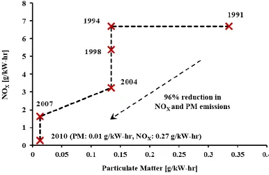
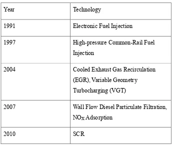
kept in-line by Environment Canada. The EPA regulations for NOX and PM
emissions [5] that apply to the on-road heavy-duty trucks are summarized in Figure 1.1.
Figure 1.1 US EPA Emission Regulations for Heavy-duty Diesel Engines
The simultaneous reductions of NOX and PM emissions continue to be a challenge for
diesel engines. Modern diesel engines are equipped with complex air and fuel
management systems to reduce the in-cylinder NOX and PM emissions. In addition,
multiple aftertreatment systems are in place to treat the diesel exhaust so that the tailpipe
CHAPTER 1: INTRODUCTION
implemented on truck engines over the past two decades [12]. Some of the engine
technologies used for emission control have resulted in a thermal efficiency reduction.
For instance, a nearly 3% (absolute) reduction in the brake thermal efficiency was
reported for the 2004 model year truck engines compared to the previous model year
engines [12]–[14].
Table 1.1 Technology Integration Example for Cummins Engines
Year Technology
1991 Electronic Fuel Injection
1997 High-pressure Common-Rail Fuel
Injection
2004 Cooled Exhaust Gas Recirculation
(EGR), Variable Geometry Turbocharging (VGT)
2007 Wall Flow Diesel Particulate Filtration, NOX Adsorption
2010 SCR
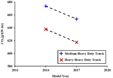
The recent additions to the EPA regulations are the CO2 emission limits, that have been
in effect since 2014. The current and proposed CO2 emission regulations [5] applied to
CHAPTER 1: INTRODUCTION
Figure 1.2 US EPA CO2 Emission Standards for Heavy-duty Diesel Engines
When hydrocarbon fuels are used, the amount of CO2 in the exhaust directly relates to the
fuel consumption, as illustrated in APPENDIX A. Therefore, a reduction of CO2
emissions requires an improvement in the thermal efficiency of the engine, in addition to
other strategies for reducing the overall vehicle fuel consumption. Moreover, the CO2
regulations are expected to become more stringent for heavy-duty engines in the near
future [15]. Similar regulations are in effect for the light-duty vehicles, which are also
likely to become increasingly stringent in the future [4]. As a result, thermal efficiency
improvements in diesel engines are necessary for their use in the heavy-duty trucks and
the light-duty passenger cars. To simultaneously meet the emission and efficiency
regulations, a more effective integration of the emission control and efficiency
CHAPTER 1: INTRODUCTION
1.3.CI Engine Control Systems
Before the introduction of electronic engine control, the CI engines implemented a
combination of mechanical, pneumatic and hydraulic subsystems for actuator
control [16]. A schematic of a typical engine control system for a traditional CI engine
equipped with a single-stage turbocharger and a mechanically operated fuel injection
system [16] is shown in Figure 1.3. Complex mechanical linkages enable the control of
fuel injection timing and quantity based on the engine speed and torque demand.
Governor-based idle and maximum engine speed control are also integrated into the fuel
injection system. The air supply system is primarily comprised of a turbocharger and an
intercooler. The turbocharger utilizes the energy from the engine exhaust to raise the
pressure of the intake air. A pneumatically-operated wastegate is used to bypass some of
the exhaust gases across the turbocharger turbine to prevent over-boosting of the engine
intake [17]. Control systems that limit the fuel quantity at low intake boost pressures are
also implemented to reduce the smoke level.
As numerous control actions are performed by the mechanical control systems, the
control complexity increases significantly when additional hardware components are
integrated into the engine for emission reduction. Moreover, the precision of the control
actions based solely on the mechanical, pneumatic, and hydraulic linkages is insufficient
to meet the stringent emission regulations [18]. Thus, the use of electronic sensors and
actuators in conjunction with an engine control unit (ECU) is a common approach for
CHAPTER 1: INTRODUCTION
Figure 1.3 Classical Diesel Engine Control Layout
A schematic of a modern CI engine is presented in Figure 1.4. In contrast to the
mechanically operated CI engine shown in Figure 1.3, the modern CI engine incorporates
emission control technologies. These include the common-rail fuel injection, two-stage
turbocharging, variable valve actuation (VVA), dual-loop EGR, and exhaust
CHAPTER 1: INTRODUCTION
The common-rail injection system and electronically operated fuel injectors facilitate
multiple injection events in one engine cycle. The air supply system, for the example
shown in Figure 1.4, consists of two turbochargers and a dual-loop EGR system. The
turbochargers utilize VGT actuators to electronically regulate the boost pressure and the
exhaust backpressure at each stage of the turbocharging system. The dual-loop EGR
system comprises the high-pressure and low-pressure EGR paths [19]. The high-pressure
EGR path connects the upstream of the VGT to the downstream of the compressor, and
the VGT vanes maintain a positive backpressure to drive the exhaust gases through the
EGR path. In the low-pressure EGR path, the exhaust gases from downstream of the
turbocharger are recirculated into the intake air, before entering the compressor. The
EGR valves and the VGT actuators work in coordination to maintain the desired intake
boost and EGR levels.
The modern diesel engines also utilize a complex exhaust aftertreatment system. A
representative configuration is shown in Figure 1.4. The DOC and the DPF are fitted
upstream of the low-pressure EGR loop. The SCR system is mounted downstream of the
DOC-DPF assembly for NOX emission control. An ammonia oxidation catalyst (AOC) is
also installed downstream of the SCR for reducing ammonia slip. An array of sensors
including mass air flow (MAF), pressure, temperature, oxygen, and NOX sensors are
deployed for the feedback based control of the intake boost, EGR, fuel injection, and
aftertreatment systems. A cylinder pressure sensor is also shown in the schematic.
However, the measurement of cylinder pressure is currently not a common practice in
CHAPTER 1: INTRODUCTION
CHAPTER 1: INTRODUCTION
1.4.Engine Calibration and Control Design
The ECU generates the control commands for a large number of electronic actuators
employed on the modern CI engine. The actuator setpoints are stored on the ECU
memory. The setpoint values are generated during the engine calibration process, which
is usually carried out in engine dynamometer test cells. Adjustments are also made to the
setpoints depending on the engine operating conditions, the atmospheric conditions, and
several other engine and vehicle parameters. A typical engine calibration process [21] is
summarized in Figure 1.5. The process is governed by several objective functions and
constrains that include engine performance targets and actuator physical limitations.
The experimental engine mapping procedure for developing the actuator setpoint maps is
highly complex and requires a significant amount of time. For instance, in engines that
use the common-rail system, several variables such as injection pressure, number of fuel
injections per cylinder per cycle, and the duty cycle of each injection event require
calibration. It is pertinent to mention that several approaches for standardization of the
calibrations across engine platforms are in place, at least within the same engine
manufacturer. Nevertheless, each new technology implemented in the engine platform
causes an increase in the complexity of the operating maps, and hence the calibration
CHAPTER 1: INTRODUCTION
Figure 1.5 Typical Engine Calibration and ECU Operation
In summary, the increased stringency of the regulatory constraints in emissions and
efficiency may require the deployment of additional sensors and actuators to facilitate
clean and efficient combustion strategies in CI engines. At the same time, the addition of
hardware components on the engine increases the calibration effort and control
complexity. Control strategies that can reduce the calibration effort and limit the sensor
requirements are necessary. The model-based control systems that are developed on the
test bench and then deployed in the ECU software are preferred. The model-based control
system development is also supported by the increasing on-board computing power on
CHAPTER 1: INTRODUCTION
1.5.Scope of Work
Dynamic control strategies are developed in this dissertation, that can reduce the energy
efficiency penalties typically associated with the simultaneous reduction of NOX and
smoke emissions in modern CI engines. A high compression ratio (18.2:1) common-rail
diesel engine is adopted as the research platform to benefit from its potentially high
thermal efficiency. The test engine is equipped with the following modern diesel engine
hardware: common-rail fuel injection, boosted intake, and EGR. In addition to the
standard engine hardware, the intake manifold of the test engine is fitted with a port fuel
injection system for implementing the dual-fuel combustion (DFC) strategy. The
single-shot diesel combustion (SSDC) and the ethanol-diesel DFC strategies are experimentally
investigated, supported by parametric calculations with zero-dimensional (zero-D) engine
cycle simulations.
The test engine is controlled using a modular control platform that includes real-time
(RT) computers and field programmable gate array (FPGA) devices. The test engine and
the control setup provide a platform to demonstrate the dynamic control strategies that
can regulate the combustion process to reduce exhaust emissions, to improve thermal
efficiency, and to maintain stable engine operation over a wide engine load range.
1.6.Dissertation Significance
This dissertation work focuses on the control of in-cylinder reductions of NOX and smoke
emissions by implementing the clean combustion strategies. The thermal efficiency of
clean combustion is improved by applying systematic control. The primary contributions
CHAPTER 1: INTRODUCTION
1. Identification of boundary conditions for the experimental study by conducting
parametric engine cycle simulations with a detailed EGR analysis.
2. Experimental investigation of low emission and high efficiency pathways with the
SSDC and DFC strategies. The adjustment of EGR rate, the modulation of
combustion phasing, and the regulation of ethanol-to-diesel ratio are used as the
primary control variables during the experimental study, the results of which are
used to develop the dynamic combustion control strategies.
3. Cycle-by-cycle control of combustion phasing and engine load using the
RT-FPGA enabled cylinder pressure analysis. Improvements in combustion stability
are achieved by implementing cycle-by-cycle control in the clean combustion
region.
4. Development of dynamic control strategies to demonstrate the systematic
regulation of EGR rate, combustion phasing, and combustion strategy switching.
1.7.Dissertation Outline
The dissertation consists of eight chapters and seven appendices. The dissertation outline
is shown in Figure 1.6. Chapter 1 provides a concise overview of the CI engine hardware
and control technologies. The regulatory and consumer requirements that drive the
continuous improvements in IC engine technologies are highlighted. The motivation for
improving engine control is explained in this chapter. A brief literature review of clean
combustion strategies and control methods for CI engines is presented in Chapter 2. The
emission benefits of diesel LTC are introduced, and the challenges associated with the
CHAPTER 1: INTRODUCTION
modifications on the emissions from CI engines are discussed. The studies of DFC are
reviewed, and the associated control challenges are summarized.
An overview of the research methodologies implemented in this dissertation is provided
in Chapter 3. The engine performance and emission targets adopted in the experimental
work are introduced. The laboratory equipment and the experimental methods are
described in this chapter. Details of the hardware and software architectures implemented
for engine control are also provided.
A zero-D engine cycle simulation code is developed, that includes a simple
characterization of EGR. Calculations are carried out to study the effects of engine
operating parameters on the engine performance, and to identify limiting conditions for
engine testing. Chapter 4 describes the calculation steps and the results of the parametric
simulation study. The results of steady-state engine tests are presented in Chapter 5. The
experimental investigation includes the systematic testing of the SSDC strategy and the
diesel-ethanol DFC strategy.
The dynamic cycle-by-cycle regulation of the fuel injection using the cylinder pressure
feedback is explained in Chapter 6. The cylinder pressure analysis technique, the
controller design, and the test results are presented. In Chapter 7, the fuel injection
control algorithm and a simplified mathematical model of the test engine are integrated
into a systematic control architecture to simultaneously regulate the air and fuel systems
of the test engine. The proposed systematic control architecture is discussed in detail,
along with representative test results. A summary of the contributions of this dissertation
CHAPTER 1: INTRODUCTION
CHAPTER 2: LITERATURE REVIEW
CHAPTER II
2. LITERATURE REVIEW
A brief summary of previous and ongoing researches in CI engine combustion is
presented in this chapter. The literature review is divided into three sections. The low
temperature combustion (LTC) strategies that can achieve ultra-low NOX and smoke
emissions using diesel fuel are reviewed in the first section. The second section presents a
brief review on the combustion of alternative fuels and fueling strategies in CI engines.
The final section summarizes the challenges and progresses of clean combustion control
in modern CI engines.
2.1.Diesel Low Temperature Combustion
The ignition and combustion characteristics of diesel engines can be explained with a
heat release rate diagram. The heat release rate (HRR) is an indication of the rate of fuel
combustion, which is calculated from the measured cylinder pressure. A representative
example of conventional diesel combustion is shown in the upper plot of Figure 2.1. The
cylinder pressure, the HRR, and the rate of injection (ROI) are plotted against the crank
angle. The short ignition delay followed by the overlap between the injection and
combustion events, suggests that a part of the air and fuel mixing occurs during the
combustion event. The temporal overlap between the fuel injection and combustion
events generally leads to diffusion burning in a diesel engine [24].
The lower plot of Figure 2.1 shows an example of the diesel low temperature
CHAPTER 2: LITERATURE REVIEW
injection pressures and commands. However, in contrast to the conventional diesel
combustion, when LTC is enabled, the combustion event is largely separated from the
fuel injection event, as seen from the ROI and HRR traces. In this case, LTC is enabled
by applying heavy amounts of EGR, which effectively prolongs the ignition delay [25].
Figure 2.1 Diesel HTC versus LTC: Pressure and Heat Release
By enabling LTC, the NOX and smoke emissions are simultaneously reduced to ultra-low
CHAPTER 2: LITERATURE REVIEW
of smoke and NOX formation regions [26], [27] is shown in Figure 2.2. During diffusion
combustion, the locally fuel-rich and high temperature conditions prevail as the air-fuel
mixing takes place simultaneously with the combustion process, thereby promoting the
formation of smoke [24]. At the same time, the diffusion flame tends to localize near
stoichiometric regions, where the high flame temperature produces high NOX
emissions [8]. Thus, during diffusion burning, the flame temperatures and the air-fuel
ratios pass through both the smoke and NOX formation regions [24], [26], [27].
Figure 2.2 Conceptual Representation of NOX and Smoke Formation
Therefore, the goal of LTC is to enhance the mixing process between the fuel and
air [28], [29]. By preparing a lean (or diluted) and pre-mixed cylinder charge before the
CHAPTER 2: LITERATURE REVIEW
diesel LTC strategies either advance or postpone the injection events away from the
injection window of conventional diesel combustion [24], [30], as shown in Figure 2.3. In
addition to the off-phasing of injection, inert dilution of the intake is applied by the use of
heavy amounts of EGR [31]. These strategies create a separation between injection and
combustion, thereby prolonging the mixing time. Even though ultra-low NOX and smoke
emissions are achieved, the thermal efficiency of diesel LTC cycles is often lower than
that of conventional HTC [29]. Besides, the LTC strategies are typically limited to low
engine load levels [28], [32]–[36].
CHAPTER 2: LITERATURE REVIEW
2.2.Combustion of Alternative Fuels in Compression Ignition Engines
Fundamentally, engine operation under the LTC regime prefers a lean (or diluted) and
homogeneous air-fuel mixture that auto-ignites towards the end of the compression
stroke. However, diesel fuels have relatively high viscosities and boiling temperatures,
hence they require a longer mixing times to prepare homogeneous mixtures. Diesel fuels
also have high tendencies to auto-ignite, which limit the mixing time prior to ignition,
especially when the engine load level is increased. Therefore, conventional diesel fuels
may not be suitable for facilitating LTC over a wide engine load range [37], [38].
Among the commercially available fuels, diesel and gasoline have high volumetric and
mass-based energy densities, which make them suitable for mobile applications. The
energy densities of some commercially available fuels are summarized in Figure 2.4. The
gaseous fuels such as H2 and natural gas have high mass-based energy densities, and are
suitable for LTC [5], [39]–[41]. But for vehicle use, these fuels have to be compressed to
high pressures for onboard storage.
Other liquid fuels such as alcohols and biodiesels that carry oxygen within the fuel
molecules have a lower energy density. Nevertheless, combustion of such fuels in CI
engines has demonstrated a reduction in the smoke emissions due to the fuel borne
oxygen [42]–[45]. Moreover, these fuels can be produced from biomass feedstock and are
CHAPTER 2: LITERATURE REVIEW
Figure 2.4 Energy Densities of Common Fuels and Energy Storage Devices
Apart from the energy content, the suitability of a fuel for LTC depends upon its physical
and chemical properties that influence the fuel-air mixing and combustion processes. The
major fuel properties that affect the mixing of fuel and air include the boiling point,
volatility, viscosity, and latent heat of evaporation; whereas the ignition characteristics
are typically evaluated from the fuel Cetane or Octane number. The properties of some
common fuels are presented in Figure 2.5. A detailed summary of the fuel properties is
CHAPTER 2: LITERATURE REVIEW
Figure 2.5 Port Injection Suitability and Ignition Properties of Selected Fuels
The fuel with a lower boiling point can readily evaporate and form a homogeneous
mixture with the surrounding air inside the combustion chamber. The combustion of this
pre-mixed fuel-air mixture generally leads to ultra-low smoke emissions [48]. The NOx
emissions can also be low if the mixture is sufficiently lean or diluted [45]. In addition to
the low boiling point, if the fuel has a high latent heat of vaporization, the evaporation of
this fuel results in the cooling of the cylinder charge [43]. The lower compression-end
temperature following the cylinder charge cooling can potentially yield lower combustion
CHAPTER 2: LITERATURE REVIEW
(ON) are often used as standard measures for the ignition quality of fuels in CI and SI
engines, respectively. While a high CN typically denotes better auto-ignition
characteristics of a fuel, a high ON implies more resistance to auto-ignition [49].
To investigate the suitability of fuel properties for LTC enabling, researchers have tested
fuels with a broad range of ignition characteristics, fuel chemistry, and volatility in CI
engines [10], [37], [38], [50]–[54]. In general, highly reactive fuels, such as diesel, are
better suited for LTC under low load conditions [35]. If fuels with high auto-ignition
resistance are employed, the low load LTC operation is challenged by the combustion
stability and thermal efficiency penalties [37]. On the contrary, the fuels with a lower
reactivity are suitable for high load operation under premixed LTC conditions, while the
highly reactive fuels can undergo premature ignition [38], [54]. The overall conclusion
from the studies of fuel property effect on CI LTC is that a dynamic modification of fuel
reactivity may be necessary for a stable operation over a wide engine operating
range [10], [37], [53].
Accordingly, the on-board fuel blending strategies, that incorporate two fuels and two
fuel supply systems are studied extensively. These on-board fuel blending strategies are
commonly identified as the dual-fuel combustion (DFC) strategies. The DFC strategy
typically employs a low pressure port injection system and a high pressure direct
injection system [10], [54], [55]. The port injection system prepares a lean and
homogeneous air-fuel mixture using a fuel that has a high auto-ignition resistance and
high volatility [56]. The direct injection system uses a high reactivity fuel, which acts as a
CHAPTER 2: LITERATURE REVIEW
ignition system [43], [48], [55], [57]–[59]. The ignition and the combustion processes are
primarily governed by the ratio between the quantities of the two fuels [10] or by the
injection timing of the direct injection fuel [60]–[63].
2.3.Opportunities for Control of Clean Combustion in CI Engines
When low engine-out NOX and smoke emissions are desired, the control of combustion is
more critical, compared to the control of conventional HTC. For enabling clean
combustion, precise control over the ignition process is necessary, while also ensuring an
adequate time for mixture preparation. If the fuel-air mixture is not sufficiently premixed
and lean (or diluted), the HTC regions are difficult to avoid [27]. Moreover, the timing of
ignition, relative to the TDC, is critical, because very early ignition can result in high
peak cylinder pressures and pressure rise rates [64]. On the contrary, very late ignition
can cause combustion instabilities [65].
In general, the mixture preparation and ignition processes are largely controlled by the
scheduling of the fuel injection, along with the regulation of intake charge quantity and
composition. The electronic engine control systems on modern CI engines provide an
effective platform to enable the highly premixed clean combustion [34]. Specifically, the
high-pressure common-rail fuel injection system facilitates the precise control over the
timing and duration of multiple injection events [66]. The enabling of the LTC strategies,
summarized in Figure 2.3, is primarily attributed to the fuel injection flexibility of the
high pressure fuel injection system [30]. Moreover, the addition of port injection to the
fuel system offers more freedom for the control of fuel delivery, while also permitting the
CHAPTER 2: LITERATURE REVIEW
variables, such as number of direct injections, injection timing, injection duration,
injection pressure, and port-injection quantity. However, the regulation of these fuel
injection variables is generally based on lookup tables [67], which require significant
calibration effort [68]. A recent development includes the integration of a cylinder
pressure sensor in a glow-plug [69], thereby providing opportunities to develop fuel
injection control algorithms based on cylinder pressure feedback [20], [70]–[72].
The air-path control hardware on a modern CI engine is equally complex. With the use of
multi-stage turbocharging, high-pressure EGR, and low-pressure EGR, a wide range of
intake boost pressures and EGR rates can be employed [73]. The application of
simultaneously high intake boost pressures and EGR ratios is possible [74], which is
often necessary for the enabling of clean combustion [25]. Furthermore, numerical
models, electronic sensors, and actuators are deployed in the air-path, which facilitate the
use of model-based air-path control algorithms, such as the regulation of the intake
oxygen concentration and air-fuel ratio [67], [75]–[80].
In summary, the literature review highlights that diesel LTC strategies are applicable at
low load levels. The engine load range can be extended by dynamically modifying the
fuel properties, for instance by employing the DFC strategy. For LTC, a tight control
over the engine operating parameters is necessary, including the fuel delivery and
air-path parameters. The integration of the cylinder pressure measurement into the engine
control system presents a potential for the improvements in the design of the engine
CHAPTER 3: RESEARCH METHODOLOGY
CHAPTER III
3. RESEARCH METHODOLOGY
3.1.Research Targets
The literature review presented in Chapter 2 suggested that the current NOX and smoke
emission regulations could be met with the diesel low temperature combustion (LTC)
strategies without exhaust aftertreatment. However, the practical implementation of
diesel LTC is restricted by the load limits, thermal efficiency penalties, control
challenges, and hardware constraints. The current approach adopted in production diesel
engines includes the operation in the HTC regime coupled with the use of selective
catalytic reduction (SCR) and diesel particulate filter (DPF) in the exhaust aftertreatment.
Low-to-moderate EGR rates are applied to reduce the NOX emissions, to maintain the
low smoke emissions, and to attain the high thermal efficiency.
The CI engines may continue to use complex aftertreatment systems to meet the stringent
tailpipe emission regulations in the near future [81]. The proposed NOX emission
regulations of 0.027 g/kW-hr (0.02 g/hp-hr) would require a NOX aftertreatment
efficiency of up to 99.5% [15], which could be cost prohibitive. A combination of
in-cylinder emission reduction and exhaust aftertreatment strategies may be required to
satisfy the future emission regulations. This dissertation work focuses on the control of
in-cylinder reductions of NOX and smoke, while lowering the associated thermal
efficiency penalty. A target value of 0.5 g/kW-hr is selected for the engine-out NOX
emissions across the entire engine load range as a platform to develop dynamic control
CHAPTER 3: RESEARCH METHODOLOGY
simultaneously low engine-out smoke and NOX emissions, and thereby to potentially
reach the future ultralow emission targets with the combined use of practical
aftertreatment techniques. Besides the emission targets, the following operability and
stability limits are set:
1. The peak cylinder pressure is limited to 170 bar.
2. The peak pressure rise rate is constrained to 15 bar/°CA.
3. The standard deviation of CA50 (STDCA50) is lower than ±1°CA.
4. The coefficient of variation of IMEP (COVIMEP) is under 5%.
The peak cylinder pressure, in part, is constrained by the noise, vibration, and
harshness (NVH) concerns. The peak pressure rise rate is normally limited to 6~8
bar/°CA in light-duty diesel engines, but in heavy-duty diesel engines this upper limit can
be increased to 15 bar/°CA [58] with better noise attenuation design. The combustion
control and stability targets are adopted to ensure that the cyclic variations are within the
normally accepted limits [3].
3.2.Research Methodology
The literature review, on the fuel impacts in CI engines, has highlighted the advantages of
the dual-fuel configuration in terms of emission reduction, combustion controllability,
and load applicability. Therefore, the single-shot diesel combustion (SSDC) and the
dual-fuel combustion (DFC) strategies are investigated in this research, which are then used to
CHAPTER 3: RESEARCH METHODOLOGY
The research methodology is summarized in Figure 3.1; therein the approach adopted to
meet the research targets is highlighted. First, parametric analysis is conducted using
numerical simulations to help identifying the boundary conditions for the engine
experiments, and to develop a better understanding of the experimental results. An EGR
calculation routine is developed as a part of the numerical simulations. Expressions are
derived for estimating the correlation between EGR application and the change in intake
gas composition for both the SSDC and DFC strategies.
The impact of the above combustion strategies on engine thermal efficiency is evaluated
at various engine load levels under steady-state testing conditions. In order to maintain
the thermal efficiency levels similar to that of the conventional diesel combustion, the
SSDC strategy is adopted to achieve the research targets at low-load operating
conditions, whereas the DFC strategy is implemented at high load levels.
The results of steady-state tests with both the SSDC and DFC strategies highlight the
effectiveness of the diesel injection command for the control of the combustion phasing.
Therefore, a controller is developed to regulate the combustion phasing on a
cycle-by-cycle basis. The measured cylinder pressure is used as the primary feedback for the
design of the control algorithm. A systematic control architecture is subsequently
developed to integrate the regulations of the boost, EGR rate, and fuel injection
commands, to attain the research targets. The control setpoints are selected referring the
parametric analyses and basing on the experimental results. These setpoints are adjusted
depending upon the engine load levels. Experiments are conducted to demonstrate the
CHAPTER 3: RESEARCH METHODOLOGY
CHAPTER 3: RESEARCH METHODOLOGY
3.3.Experimental Setup
The current section presents the detailed descriptions of the test engine setup, the test
control system, and the measurement equipment. The procedures for data acquisition and
synchronization between the measurement devices are explained, followed by a
discussion of the post-processing techniques.
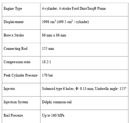
3.3.1. Test Engine
The experiments are mostly performed on a production 2.0 L Ford Puma common-rail
diesel engine. The detailed specifications of the test engine are summarized in Table 3.1.
The engine is coupled to a non-motoring eddy-current dynamometer. The base engine is
modified to separate the intake and exhaust systems of the first cylinder from the other
three cylinders. The research and measurements are conducted on the first cylinder like a
single cylinder engine, while the remaining three cylinders are operated in the
conventional high temperature combustion (HTC) mode. Unlike a motoring
dynamometer, a non-motoring dynamometer cannot maintain the engine speed at the
desired setpoint if the engine operates below a certain load level. By operating these three
cylinders in the stable combustion regime, potentially unstable combustion strategies can
be investigated on the research cylinder using this non-motoring dynamometer.
A piezo-electric, un-cooled, and glow-plug mounted pressure transducer (AVL GU-13P)
is installed in the research cylinder for in-cylinder pressure measurements. The
membrane of the pressure transducer is nearly flush-mounted to minimize the resonance
CHAPTER 3: RESEARCH METHODOLOGY
An external conditioning unit regulates the coolant temperature to a setpoint of 80°C
during the tests. The temperature is chosen to represent a fully warmed up engine. The
original oil circulation system is used for the lubrication of the engine components.
External measurement systems are added for monitoring the oil pressure and temperature.
Alarms are in place to warn the operator if the coolant or oil conditions are outside the
safe limits.
Table 3.1 Test Engine Specifications
Engine Type 4-cylinder; 4-stroke Ford DuraTorq® Puma
Displacement 1998 cm3 (499.5 cm3 / cylinder)
Bore x Stroke 86 mm x 86 mm
Connecting Rod 155 mm
Compression ratio 18.2:1
Peak Cylinder Pressure 170 bar
Injector Solenoid type 6 holes; Φ: 0.13 mm; Umbrella angle: 155°
Injection System Delphi common-rail