ABSTRACT
YI, CAO. Digital Printing with Laser Etching: Design Potential and Performance Implications. (Under the direction of Dr. Traci May Lamar).
Both laser engraving technology and digital printing have been developed individually
for textiles with an eye to productivity, sustainability and quality, but the combination of
these two technologies has not been investigated in a structured way. Laser engraving is
accurate and repeatable, and can change the appearance or surface of textiles and so allow
users to develop their own unique fabrications from a single base cloth. Digital printing
transfers surface pattern designs to textiles, which adds ornamental value to products in a
flexible way. Compared to conventional printing technology, the technology of digital inkjet
printing offers advantages in process efficiency, ease of use, cost effectiveness, design
versatility and environmental friendliness. Melding laser engraving and digital inkjet printing
not only creates a unique look for textiles, but it also combines advantages of laser engraving
and digital printing and could increase the flexibility and design responsiveness of a fabric
production system. In this paper, a textile design method combining laser engraving and
digital printing on a non-denim fabric was explored. Digital printing brought pattern designs
to the engraved white fabric. The laser engraving removed some of the pigments and fabric
surface, causing de-coloration along with creation of textures to the fabric. The properties of
the laser-engraved digital-printed cotton twill fabric, including weight, tearing strength, air
resistance, color appearance and abrasion resistance were investigated to provide objective
data regarding the physical properties of the engraved and printed fabric. The goal was to
understand if laser etching on a plain white fabric could be effective in creating fabric texture
variation without destroying the integrity of the fabric. As a result, different physical
energy, including laser power, laser pixel time and resolution. Clear patterns can be achieved
applying higher laser energy and vague laser engraving patterns can be achieved using lower
laser energy. Also, different physical properties and aesthetic effects of the fabric can be
achieved by applying different laser energy, including laser power, laser pixel time and
resolution. Clear patterns can be achieved applying higher laser energy and vague patterns
can be achieved using lower laser energy. The experimental results also revealed that the
changes in the physical properties are mainly related to the vaporized surface pigments and
fibers and cracks, wrinkles and pores formed on the fiber surface with the increment of laser
energy applied, resulting in the decrease of weight, tear strength, abrasion and air resistance.
© Copyright 2017 by Yi Cao
Digital Printing with Laser Etching: Unique Design Potential and Flexibility
by Yi Cao
A thesis submitted to the Graduate Faculty of North Carolina State University
in partial fulfillment of the requirements for the degree of
Master of Science
Textiles
Raleigh, North Carolina
2017
APPROVED BY:
_______________________________ _______________________________
Dr. Tracy May Lamar Dr. Lisa Parrillo-Chapman
Committee Chair
ii
DEDICATION
This work is dedicated to my Parents for their loving and financial support. I would like
to thank Dr. Renzo Shamey, Teresa White, Tri Vu, Ming Wang and Nian Xiong for their
assistance. To my Professors and committee members Dr. Lisa Parrillo-Chapman and Dr.
Andre West for their assistance and teachings. Most of all to my Committee chair Dr. Traci
May Lamar for all her guidance, teachings, support and without her this research would not
iii
BIOGRAPHY
Yi Cao was born April 4, 1994 in Wuxi, China. She is the only daughter of Xiaochun
Cao and Yuehua Wang. She attended Meicun High School and graduated in July of 2009. In
September, Yi attended Donghua University in China for three years and was accepted into
the College of Fashion and Art Design before taking part in the 3+X master program
cooperating with NC State University in 2015. At DHU he attained his Bachelor of Fashion
Design and Engineering in June of 2016. She has been accepted to Department of Textile,
Apparel, Technology and Management in NCSU since 2015.
Under the persuasion and encouragement of her instructor Dr. Traci May Lamar, Yi
applied to the Masters of Science program and started in August. While pursuing her
Master’s degree she was awarded a teaching assistantship with Dr. Traci May Lamar,
iv
TABLE OF CONTENTS
List Of Tables... VII
List Of Figures ... VIII
Glossary ... X
Chapter 1 Introduction ... 1
Chapter 2 Literature Review ... 4
2.1 Introduction Of Three Laser Technologies ... 4
2.1.1 CO2 Gas Laser... 5
2.1.2 Fiber Laser And Nd: Yag Laser... 5
2.2 CO2 Laser Cutter ... 6
2.3 The Application Of Laser In Fashion And Textile Design ... 7
2.3.1 Laser Marking ... 8
2.3.2 Laser Engraving ... 8
2.3.3 Laser Etching ... 9
2.3.4 Challenges Of Laser Technology Applications In Fashion And Textile Design .... 10
2.4 Introduction Of The Ink-Jet Digital Printing ... 10
2.4.1 Two Types Of Digital Ink-Jet Printers ...11
2.5 Technical Aspects Of Digital Inkjet Printing In Textiles ... 14
2.5.1 Digital Ink-Jet Printing Inks... 16
v
2.5.3 Color Management Of Digital Ink-Jet Printing ... 25
2.6 Challenges Of Digital Ink-Jet Printing ... 26
2.6.1 Common Defects Of Digital Ink-Jet Printing ... 26
2.6.2 Limitations Of Digital Inkjet Printing Technology ... 28
2.7 Summary ... 29
Chapter 3 Methodology ... 31
3.1 Pilot Investigation ... 31
3.2 Material ... 32
3.3 Experimental Sample Preparation ... 32
3.4 Laser Engraving Process ... 33
3.5 Digital Printing Process ... 34
3.6 Testing The Properties Of The Laser Engraved Digital Printing Fabric ... 35
3.6.1 Fabric Surface Appearance ... 36
3.6.2 Color Appearance... 36
3.6.3 Fabric Weight ... 37
3.6.4 Air Permeability ... 37
3.6.5 Tearing Strength ... 37
3.6.6 Abrasion Resistance ... 38
Chapter 4 Results ... 39
4.1 Fabric Surface Appearance ... 39
vi
4.3 Fabric Weight ... 44
4.4 Air Permeability ... 47
4.5 Tearing Strength ... 51
4.6 Abrasion Resistance ... 58
Chapter 5 Discussion And Conclusion ... 62
vii
LIST OF TABLES
Table 1. Digital Textiles Inkjet Printing Inks, Color Fiber- Interaction and Finishing
Techniques (Magdassi, 2010) ... 22
Table 2. Typical Pretreatment Recipes (by Weight) for Textiles (Choi, et al., 2004) ... 23
Table 3. Laser Engraving Parameters for Experimental Sample Preparation ... 32
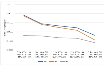
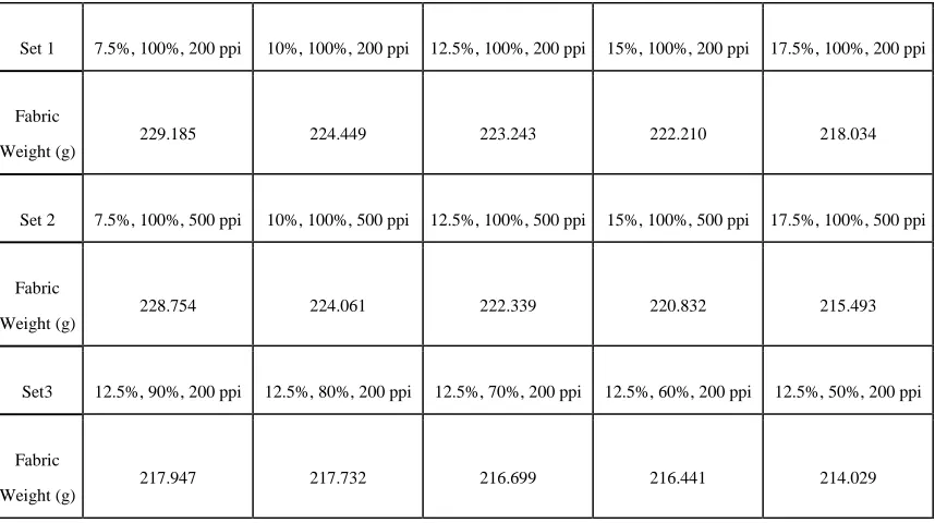
Table 4. Results of Fabric Weight after Changing Laser Power (%), Speed (%), and
Resolution (ppi) ... 45
Table 5. Air Permeability of Laser-engraved Samples ... 49
Table 6. Relationship Between Laser Power, Speed, Resolution and Tear Strength in Warp
Direction ... 53
Table 7.Relationship Between Laser Power, Speed, Resolution and Tear Strength in Weft
Direction ... 54
Table 8. Tear Strength Requirements for Different Kinds of Apparels ... 58
viii
LIST OF FIGURES
Figure 1. Content of the Paper ... 2
Figure 2. Purpose of Study... 3
Figure 3. Classification of Fine Resolution Inkjet Printer ... 13
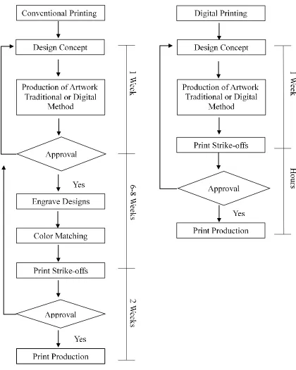
Figure 4. Production Process of Conventional Printing vs. Digital Inkjet Printing (Gupta, 2001) ... 15
Figure 5. The Classification of Ink-jet Inks ... 17
Figure 6. UNIVERSAL VLS6.60 laser cutter. (2017, January 18). Retrieved from https://www.ulsinc.com/build/manual-platform-overview on 2017, January 18. ... 34
Figure 7. Digital Printing Pattern ... 34
Figure 8. MUTOH Mc3 Nano Pigment Printer ... 35
Figure 9. Macbeth Color-Eye 7000A spectrophotometer (Gretag Macbeth, New Windsor, NY, USA) ... 37
Figure 10. Falling-pendulum (Elmendorf - Type) Apparatus ... 38
Figure 11. Nu-Martindale Abrasion and Pilling Tester ... 38
Figure 12. Scan Images of Laser-engraved Samples (a) Set 1: Speed and resolution constant, laser power changed; (b) Set 2: Speed and laser power constant, resolution changed; (c) Set 3: Laser power and resolution constant, speed changed ... 40
Figure 13. Color Differences in Orange Area ... 43
Figure 14. Color D in Black Area ... 43
ix
Figure 16. Impact of Speed Decrease on Fabric Weight Loss ... 46
Figure 17. Impact of PPI Increase on Fabric Weight Loss ... 46
Figure 18. Impact of Power Increase on Fabric Weight Loss ... 47
Figure 19. Air Permeability of laser-engraved samples. ... 48
Figure 20. Air Permeability Change due to Speed Decrease ... 50
Figure 21. Air Permeability Change due to Power Increase ... 50
Figure 22. Air Permeability Change due to PPI Increase ... 51
Figure 23. Tear Strength of Laser-engraved Samples in Warp Direction ... 51
Figure 24. Tear Strength of Laser-engraved Samples in Weft Direction ... 52
Figure 25. Tear Strength Change in Warp Direction due to Speed Decrease ... 53
Figure 26. Tear Strength Change in Warp Direction due to Power Increase ... 54
Figure 27. Tear Strength Change in Warp Direction due to PPI Increase ... 54
Figure 28. Tear Strength Change in Weft Direction due to Speed Decrease ... 55
Figure 29. Tear Strength Change in Weft Direction due to Power Increase ... 56
Figure 30. Tear Strength Change in Weft Direction due to every 300 PPI ... 56
Figure 31. Abrasion Resistance of Laser-engraved Digital-printed samples ... 59
Figure 32. Abrasion Resistance Change due to Speed Decrease ... 59
Figure 33. Abrasion Resistance Change due to Power Increase ... 60
x
GLOSSARY
Kerf- the width of a slit or notch made by a saw or cutting torch
Gain medium- a gain medium is either a gas, liquid, or solid that provides means for
optical gain, which is generated by stimulated emission on transitions from higher to lower
states. It can amplify the power of light.
Spot size- the radius of the beam (Geoff, 2006)
Fabric decoherence- the loss of quantum coherence of fabric. A holistic property,
ascribable, presumably in varying degrees, to the system as a whole, much as the property of
fabric strength (Bender, 1989).
Droplets/s/nozzle- the speed of the printer ejection, number of droplets of each nozzle
ejects per second
1
CHAPTER 1 INTRODUCTION
In recent years, the application of digital inkjet printing in textile products has drawn
increasing interest (Kan & Yuen, 2012). The digital inkjet printing technique stands out for
benefits like speed, flexibility, creativity, cleanliness, competitiveness and also
eco-friendliness (Gupta, 2001). Compared to conventional screen printing methods, digital inkjet
printing offers advantage for short runs. Sampling or proofing using a digital inkjet printer is
easy and economical for that it needs no screen (Gupta, 2001). Consequently, all costs
causing by screen engraving, paste making, strike-offs, downtime and wastage are eliminated
(Kan & Yuen, 2012). Also, as Kan and Yuen mentioned, there are no registration problems in
terms of repeat size. This technology is suitable for just-in-time delivery and mass
customization. However, the digital inkjet printing is still limited by the machine itself,
pigment choice and material choice (Sivaramakrishnan, 2016).
Laser technology can be used for various applications on materials ranging from metals
to textiles (Bogue, 2015).CO2 gas lasers are widely and successfully applied onto different
products ranging from home textiles to fashion accessories (Brown & Arnold, 2010). Laser
treatment is a sustainable technology entirely different from traditional textile processes, as it
allows relatively quick surface designing with good precision. There are several other
advantages of using laser over the conventional methods in cutting, engraving, embossing,
denim fading etc. (Tyler, 2005). In addition, laser involves lower risk of product damage and
low use of consumables (Kan, Yuen, & Chen, 2010). The laser equipment of today has
2
cumbersome and hard to maintain. However, modern equipment is easy to operate, simple to
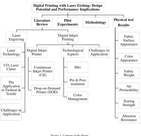
learn and easy to maintain (Majumdar & Manna, 2003). Figure 1 shows the content of this
paper.
Figure 1. Content of the Paper
Digital Printing with Laser Etching: Design Potential and Performance Implications
Literature Review Laser Engraving Laser Technology
CO2 Laser Cutter
The Application in Fashion &
Textile Challenges in Application Digital Inkjet Printing Digital Inkjet Printer Continuous Inkjet Printer (CIJ) Drop-on-Demand Printer (DOD) Technological Aspects Inks
3
1.1 Purpose of Study
Both of laser engraving technology and digital printing have achieved increasing
development in textile, but the combination of these two technologies has not been
investigated yet. In this paper, a textile design method combining laser engraving and digital
printing on a non-denim fabric was explored. Digital printing brought pattern designs to the
white engraved fabric, which in practice adds ornamental and commercial value. The laser
engraving removed some of the fabric surface, causing coloration or de-coloration along with
creation of textures to the fabric. The properties of the laser-engraved digital-printed cotton
twill fabric, including fabric weight, tearing strength, air resistance, color appearance and
abrasion resistance were investigated to provide objective data regarding the physical
properties of the engraved and printed fabric. The goal was to understand if laser etching on a
plain white fabric could be effective in creating fabric texture variation without destroying
the integrity of the fabric and to share learnings regarding the aesthetics and practicality of
this combination of treatments.
Figure 2. Purpose of Study
Digital Printing
Laser Engravin
g
Combination
• Non- denim (cotton twill) • Aesthetic & Commercial
4
CHAPTER 2 LITERATURE REVIEW
2.1 Introduction of Three Laser Technologies
Laser is an energy source, whose intensity and power can be precisely controlled. The
laser beam can be focused to a material at specific angle depending on the application
(Nayak & Padhye, 2016). Laser can cut a variety of materials ranging from fabric which is
flexible to metal which is rigid and strong (Belli, Miotello, Mosaner, & Toniutti, 2005).
Different laser types are commonly named according to the state or the physical properties of
the active medium (Majumdar & Manna, 2003). Consequently, there are crystal, glass or
semiconductor, solid state lasers, liquid lasers, and gas lasers (Majumdar & Manna, 2003).
Laser technology, as one of the most important light-based technologies, has rapidly
developed to be an efficient method in multiple industries such as textile, leather and garment
industries due to its accuracy, efficiency, simplicity and the scope of automation (Bogue,
2015).
Different industries need different laser machines, determined by the laser sources
(Robert Bogue, 2015). Cutting is a major laser application of those machines (Nayak &
Padhye, 2016). Laser cutting is also a thermal process, but because of the high degree of
focus of the laser, the precise laser beam and a small thermal diffusion area, leaving an edge
with a high-quality finish, laser process is very suitable for cutting fabrics(Robert Bogue,
2015). Depending on the material thickness, it is possible to make kerf widths as small as 0.1
mm (Robert Bogue, 2015). In this paper, there are three laser technologies will be introduced,
5
aluminum garnet) (Hecht, 1986).
2.1.1 CO2 Gas Laser
The carbon dioxide laser is the most popular laser used in industrial material processing
because of its high efficiency and high average optical power output (Chryssolouris, 2013).
CO2 lasers use a mixture of gases such as helium and nitrogen, with CO2 being the most
predominant to create a cut quality similar to that of milled edges of mild steels and can
operate in continuous wave (CW) or pulses (Chryssolouris, 2013).
A CO2 laser has the following characteristics. First, it has a wavelength of 10.6 µm and
it is in the far infra-red spectrum thus not visible (Dahotre, 1998). The laser beam is well
absorbed by organic materials and ceramics but poorly absorbed by metallic materials
(Dahotre, 1998). Second, mirrors rather than optical fibers are used for beam delivery since
normal glass or silica in optical fibers is not transparent to the CO2 laser beam (Dahotre,
1998). Carbon dioxide lasers are widely used laser types (Yuan, Jiang, Newton, Fan, & Au,
2012). Specifically, the CO2 laser is suited for materials such as wood, acrylic, glass, paper,
textiles, plastics, films, leather, stone (Yuan, Jiang, Newton, Fan, & Au, 2012; Bogue, 2015).
2.1.2 Fiber Laser and Nd: YAG Laser
Both the fiber laser and the ND: YAG laser (crystal laser) belong to the solid-state laser
group that are now becoming popular in metal cutting industry (Nayak & Padhye, 2016;
Wandera, 2006). Fiber laser is produced from a solid gain medium without the use of any
liquid or gas (Nayak & Padhye, 2016). The major advantage of the fiber laser is the
extremely small spot size (Nayak & Padhye, 2016). Fiber lasers and ND: YAG lasers can
6
both produce an extremely small spot size, which makes it ideal for cutting reflective metals
(Nayak & Padhye, 2016; Wandera, 2006). Except for metals, coated metals and plastics are
also the main materials that can be modified with these two light-based technologies
(Wandera, 2006). Pulsed and continuous-wave Nd: YAG types are mostly used for cutting
metals, silicon and ceramics (Bogue, 2014).
2.2 CO2 Laser Cutter
“One of the first industrial laser cutting machines was invented by Messer Griesheim in
1972, and further development of laser cutting machines in the 1970s and 1980s led to a
widespread use of laser cutting” (Vilumsone-Nemes, 2012). Laser cutters have had wide uses
in the apparel and textile industry, for tasks such as the replacement of manual cutting of
garment pattern pieces and garment pattern markers in the apparel manufacturing process
(Rorah, 2016). Laser cutters are also being used for smaller scale cutting to add intricate
detail to garments (Rorah, 2016). Because of the wide spectrum of uses, laser cutters are
being implemented in apparel design firms, apparel design programs in universities and
colleges, as well as small businesses (Rorah, 2016).
“CO2 laser cutters perform using a beam of thermal energy that bounces off several
mirrors and a lens which focuses the beam onto the material at a very specific point” (Bogue,
2015). CAD systems allow for “instant communication with the main control unit, and allow
technicians to preprogram multi-step commands, set parameters, and start the process with a
single-keystroke” (Pundir, 2007). The laser beam of the CO2 laser cutter is intended to have a
small kerf width while cutting without contact along vector lines that can be created in vector
7
cutting or engraving parameters including cutting PPI (PPI means pixels per inch, which is a
measure of the sharpness), cutting quality grade, cutting power and cutting speed can be set
manually or adjusted according to the database (Yuan, Jiang, Newton, Fan, & Au, 2012). The
laser cutting process utilizes both hardware and software systems, including the vector
graphic design software and the laser software that are key components to laser cutting
(Rosa, 2015).
2.3 The Application of Laser in Fashion and Textile Design
Laser technology has been used in the apparel industry from the nineteenth century
(Nayak & Padhye, 2016). Recently the use of lasers in the apparel industry is increasing.
Lasers are used in cutting garment patterns, patterning designer neckties, 3D body scanning,
denim fading and engraving leather (Nayak and Khandual, 2010). The major reasons for
wide application of laser in garment industries may be due to no physical contact, no water,
dyestuff and solvents applied, a high degree of automation and fast and precise engraving
(Kovacset al. 2006; Yuan et al. 2012).
Other than cutting, laser coloring or discoloring is another common application of laser
technology in textiles (Majumdar & Manna, 2003). In the process of laser coloring or
discoloring, a thin oxide layer on the surface developed by controlled laser irradiation may
produce a particular color (Majumdar & Manna, 2003). Juciene et. al. (2014) states that this
technology can change the appearance or surface of textiles so it allows users to develop their
own unique fabrications. In general, laser coloring can be divided into laser marking, laser
engraving and laser etching (Azuma & Sakaki, 1989). Although these terms are often used
8
applications and attributes that make it ideal for different jobs.
2.3.1 Laser Marking
Marking is a process to make a mark on a product for the purpose of product
identification (Qi, Wang, & Zhu, 2003). Laser marking is what happens when the laser beam
interacts with the surface of a material where has a pigment layer, changing its internal
molecular structure of pigment to change its color (Azuma & Sakaki, 1989). It is achieved by
moving a low-powered beam slowly across the material, in which the heat from the laser
redistributes the carbon without damaging the surface and creates high-contrast marks
(Webmaster, 2015).
Laser heats the material, causing oxidation under the surface and changing the color of
the material (Webmaster, 2015). For example, it applies low temperatures to metal to anneal
the surface. All of this is done while leaving the surface intact (Webmaster, 2015). Laser
marking is less common than laser engraving and laser etching (Webmaster, 2015).
2.3.2 Laser Engraving
“Laser engraving is a process where the laser beam physically removes the surface of
the material to expose a cavity that reveals an image at eye level” (Webmaster, 2015). The
laser creates high heat during the engraving process, which essentially causes the material to
vaporize and creates a cavity in the surface that is noticeable to the eye and touch
(Webmaster, 2015). Laser engraving is used as one main application of laser technology in
fashion and textile areas (Yuan, Jiang, Newton, Fan, & Au, 2012). (Zhou et al., 2009). It
allows short-time surface designing of patterns with precision, desired variety, size and
9
minimum damage to the material at a selected wavelength and laser power density. Through
the laser engraving process, the texture and surface color can be removed and multi-level
color effects can be generated on the fabric surface (Ondogan et al., 2000). Compared to
traditional engraving, laser engraving can be done faster on several materials and also it is
more reliable in for that there is a smaller chance of product damage or deformation
(Webmaster, 2015).
The most commonly used fabrication for laser treatment is denim (Juciene, Urbelis,
Juchneviciene, & Cepukone, 2014). When replicating a decorated, destructed, or worn out
denim wash, the laser cutter eliminates some of the substances that are used in traditional
methods that were considered to be harmful to the environment (Juciene, Urbelis,
Juchneviciene, & Cepukone, 2014; Ondogan, Pamuk, Ondogan, & Ozguney, 2005), plus it
eliminates the use of water to achieve this aesthetics. Use of laser technologies such as
engraving eliminates abrasion or distortion of the textile from the denim wash process,
leaving behind the traditional methods of sanding and stoning (Juciene, Urbelis,
Juchneviciene, & Cepukone, 2014; Ondogan, Pamuk, Ondogan, & Ozguney, 2005).
2.3.3 Laser Etching
In laser etching, the material being etched is not touched by anything. A small laser
removes material to create the image, causing less risk for damaging the material. Unlike
engraving, the depth in etching is typically no more than 0.001” (Webmaster, 2015).
Researchers have defined attributes of laser etching as follows. First, there is an apparent
color change between original textile and etched part of textile (Juciene, Urbelis,
10
are no apparent holes or through-cutting on the etched part of the textile (Juciene, Urbelis,
Juchneviciene, & Cepukone, 2014; Yuan, Jiang, Newton, Fan, & Au, 2012)
2.3.4 Challenges of Laser Technology Applications in Fashion and Textile Design
While the development of laser cutting and laser engraving is rapid and promising, there
are still some technical problems and disadvantages of laser treatments which have limited its
application into fashion and textile industries (Yuan, Jiang, Newton, Fan, & Au, 2012). There
are some of the disadvantages of laser treatment such as the use of a large amount of energy,
inability to process reflective materials and a large initial purchase cost to access the machine
limit laser adoption (Vilumsone-Nemes, 2012). Also, it is possible to create toxic fumes in
the processing of certain materials with a particular chemical make-up or finish
(Vilumsone-Nemes, 2012). Moreover, the laser engraving process can change the structure of the
fabrication unexpectedly due to thermal effects (Vilumsone-Nemes, 2012). This situation
happens often, especially for woven and knitted fabrics, which require stable structures to
keep good quality (Zhang, 2007). Fabric de-coherence affects people’s feeling of dressing as
well as the appearance of the garment (Zhang, 2007). So, durability is one major factor that
restricts the widespread use of laser technology in the textile and fashion industry (Zhang,
2007).
2.4 Introduction of the Ink-jet Digital Printing
Digital ink-jet printing is a non-contact process that enables a design to be transferred
directly from the computer onto substrates such as film, paper, fabric, plastic and even
electronic components (Kan & Yuen, 2012). The technology of digital ink-jet printing uses
11
for running heavy-duty machinery (Kan & Yuen, 2012). In general, digital ink-jet printing is
now a promising technology in the textile and fashion industry for that it offers advantages in
process efficiency, ease of use, cost effectiveness, design versatility and friendly environment
impact (Patil, Husovska, Pekarobicova, & Fleming, 2016).
Digital ink-jet printing technology was pioneered in Japan in the 1980s (Kan & Yuen,
2012). Although the idea had been developed for more than two decades, it was not until
around 2000 that equipment became adequate enough for processing on textiles due to the
high cost (Gupta, 2001). The first commercially available digital ink-jet printing system for
textiles was introduced in 1991. It was a continuous stream type which used Procion P
(monochlorotriazinyl) reactive dyes in ink formulations for printing cellulosic fabrics (Kan &
Yuen, 2012). Not until 2007 were digital ink-jet printing machines that could produce at
speeds of up to 300m2/ hour were showed in a large portion of the International Textile
Market Association (ITMA) exhibition (Yuen et al., 2008).
2.4.1 Two Types of Digital Ink-jet Printers
In the case of digital ink-jet printing on textiles, printing speed and print head life are
the critical hardware issues for commercial and technical considerations (Kan & Yuen, 2012).
A digital printing system for application on textiles is an integration of four components,
including the inkjet head, ink chemistry, media and the color management software (Gupta,
2001). There are various technologies and suppliers existing for each component (Gupta,
2001). There are two major types of digital ink-jet printers available, namely, (i) coarse
resolution type, and (ii) fine resolution type (Kan & Yuen, 2012). The coarse resolution type
12
offers finer resolution of up to 300 lines per inch (Kan & Yuen, 2012).
2.4.1.1 Coarse Resolution Digital Ink-jet Printer
Coarse resolution digital ink-jet printers are normally based on valve technology (Kan &
Yuen, 2012; Malik, Kadian, & Kumar, 2005b). There are mainly two commercially available
systems, Millitron system and Chromo jet system (Malik, Kadian, & Kumar, 2005).
“Millitron system uses an array of jets with a continuous stream of dye liquids, which can be
deflected by a controlled air jet, whereas Chromo jet uses computer activated on/off valve
systems to control the flow of liquids” (Malik, Kadian, & Kumar, 2005). But resolutions of
these systems are relatively coarse, reaching a maximum of 40 dpi (dots per inch), which
have been only accepted by the carpet industry in the field of textile printing and are not
acceptable in the field of textile printing (Malik, Kadian, & Kumar, 2005).
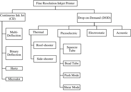
2.4.1.2 Fine Resolution Digital Ink-jet Printer
Fine resolution digital ink-jet printers operate basing on either continuous ink-jet (CIJ)
technology or drop-on-demand (DOD) technology (Malik, Kadian, & Kumar, 2005). The
detailed map of fine resolution digital inkjet printing technologies is shown in Figure 3
13 Figure 3. Classification of Fine Resolution Inkjet Printer
In continuous mode inkjet printing (CIJ), the ink is pumped through a small nozzle (15
μm diameter) continuously and selectively charged for printing of designs, providing a
resolution of up to 2880 dpi (Gans, Duineveld, and Schubert, 2004; Malik et al., 2005).
Continuous-mode inkjet printers have a high rate of droplet ejection which is around 50,000
to 100,000 droplets/second, making it used mainly for high-speed graphic applications such
as textile printing and labeling (Gans, Duineveld, and Schubert, 2004). There are four
methods of CIJ printing, namely multilevel, binary, hertz and microdot (Malik, Kadian, & Fine Resolution Inkjet Printer
Continuous Ink Jet (CIJ)
Multi-Deflection
Binary Deflection
Hertz
Microdot
Drop-on-Demand (DOD)
Thermal
Roof-shooter
Side-shooter
Piezoelectric
Squeeze Tube
Bead Tube
Push Mode
Shear Mode
14
Kumar, 2005).
Drop-on-demand ink-jet printers (DOD) are used in majority of ink-jet printing
activities (Gans, Duineveld, and Schubert, 2004; Malik et al., 2005). In this method, an
individual ink droplet is ejected from a reservoir through a nozzle according to electrical
impulses (Malik, Kadian, & Kumar, 2005). These systems control the flow of ink droplets to
an air stream that carries the droplets to the substrate by using solenoid valves (Malik,
Kadian, & Kumar, 2005). DOD systems operate at the maximum ejection rate at about
25,000 droplets/s/nozzle which is lower droplet production rate than the CIJ systems (Malik,
Kadian, & Kumar, 2005). In the group of DOD printers, there are four technologies, namely
piezoelectric, thermal excitation, electrostatic and acoustic (Malik, Kadian, & Kumar, 2005).
2.5 Technical Aspects of Digital Inkjet Printing in Textiles
Digital ink-jet printing can produce small quantities of high quality products, such as
products with rich color content and specific design in a less expensive way (Malik, Kadian,
& Kumar, 2005). It has been developed to either replace or cooperate with conventional
printing in the textile industry, in which it is currently used for small quantities (per design);
curtains, decorative and furniture fabrics, home textiles, wall paper, carpets, woven ribbons
and labels, banners and flags, ties and scarves and so on (Kan & Yuen, 2012). However, use
of digital ink-jet printing for textiles is different from conventional printing methods in
several aspects, including pattern design preparation, ink requirements, hardware of the
digital inkjet printing system, color management of the printing and treatment of the fabric
(Kan & Yuen, 2012). Also as Figure 4 shows, the digital inkjet printing offers distinct
16
2.5.1 Digital Ink-jet Printing Inks
One important component of the digital printing besides the machinery is the ink, which
is the central factor for efficiency, and economy as well as the long-term stability of inkjet
printing (Malik, Kadian, & Kumar, 2005). Ink-jet inks are generally classified into two broad
categories namely 1. Base 2. Colorant (Magdassi, 2010). The base refers to the media
through which colorant is dissolved or dispersed and applied while the colorant refers to the
type of colorant being used within the medium for example, reactive dyes, organic or
polymeric dyes or disperse colorant such as pigment and disperse dyes (Le 1998, Niaounakis
2015a, Pekarovicova 2015b).
Colorants used in digital ink-jet printing must fulfill essential requirements such as high
purity, high chroma, clear tone of the color, high solubility in water and acceptable wet and
light fastness properties on printed fabrics (Kan & Yuen, 2012). Therefore, in developing the
colorant system for digital ink-jet printing, the system should possess these basic
characteristics (Kan & Yuen, 2012). Various colorant systems selected for digital ink-jet
printing are shown as follows: reactive dye based ink, disperse dye based ink, acid dye based
17 Figure 5. The Classification of Ink-jet Inks
18
2.5.1.1 Reactive Dye Based Ink
Inks based on reactive dyes can be used to print cotton, viscose or cellulosic fibers and
to some extent wool and silk (Malik, Kadian, & Kumar, 2005). The reactive dye is the only
class of dyes that makes covalent bonds with the fiber chemically and becomes part of it,
which gives reactive dyes high levels of washing and light fastness (Chinta & Shrivastava,
2013). Depending on the chemical constitution, reactive dyes can be classified as: 1.
Chlorotriazine Dyes (MCT) 2. Vinyl Sulphone Dyes (VS) 3. Heterocyclic Helogen
Containing Dyes (HHC) and 4. Mixed Dyes (MCT-VS) (Chinta & Shrivastava, 2013). By
depending on application methods of temperature, reactive dyes can be classified as cold
brand reactive dye (applied in a low temperature, i.e. room temperature), hot brand reactive
dye (applied at a medium temperature around 60℃) and high exhaust brand reactive dye
(applied at 80-90℃) (Chinta & Shrivastava, 2013).
When applying reactive dyes, alkali treatment and heat application are required in order
to achieve full chemical reaction, forming strong covalent bond with the cellulosic fiber
(Malik, Kadian, & Kumar, 2005). A wide range of color can be produced with reactive dyes.
Also, the price of reactive dye is comparatively cheaper (Chinta & Shrivastava, 2013). Heat
is applied after printing, by a steam or hot air fixation process (Kan & Yuen, 2012). A
separate washing process must be applied to wash off any unfixed reactive dye and to ensure
optimum fastness (Kan & Yuen, 2012).
2.5.1.2 Disperse Dye Based Ink
19
polyester (Malik, Kadian, & Kumar, 2005). Disperse dye inks are produced by dispersing
hydrophobic dye particles in water (Hitoshi, Toshiya, & Yasuhiko, 2004). These dye particles
are physically small and planar, enabling a closer approach to the polymer chains (Tyler,
2005). They have polar functional groups (such as –NO2 and –CN) that can produce bonds
with the polyester molecules (Tyler, 2005). Dyeing is done at elevated temperatures and
pressures so that the crystallites swell and offer more sites for bonding, enabling the dyed
polyester fabric to be fast to washing (Tyler, 2005).
Disperse dye molecules are more volatile than other colorants, which has led to the
development of transfer printing of polyester (Tyler, 2005). Transfer inks are based on a
special type of disperse dye that can be printed onto paper and then transferred to textiles
using a heat press (about 200 oC). There are also disperse dye-based inks that have particular
fastness properties that can be applied directly to the substrate, generally using high
temperature steam to fix the dye (Kan & Yuen, 2012).
2.5.1.3 Acid Dye Based Ink
Acid dyes are used for printing directly to nylon, wool, silk or polyamide fabrics with a
protein base (Kan & Yuen, 2012). Although acid dyes account for only a small proportion of
all dyes, they are still quite important for digital inkjet printing as many high-quality designs
to be printed on luxurious fabrics such as wool and silk require acid dyes (Malik, Kadian, &
Kumar, 2005). The main advantage of acid dye inks is that they produce bright colors that
offer a variety of applications. Another advantage is the light fastness of the inks, which is
20
prevent wicking of the ink on the fabric (Kan & Yuen, 2012). A post-printing treatment, such
as steaming, is necessary for dye fixation and a separate wash-off process ensures removal of
any unfixed dye (Yang & Li, 2003).
2.5.1.4 Pigmented Ink
Pigment printing is an important coloration system that accounts for almost half of all
printed textiles produced worldwide (Kan & Yuen, 2012). Pigment inks are used to achieve
print qualities of durability, light fastness and UV- resistance (Tyler, 2005). Colored pigment
is bound to the substrate using a cross- linking binder system after a heat treatment (Tyler,
2005). The advantage of pigments is that the application of pigments does not require
pretreatment or washing process when they can be applied to many different substrates so
that the overall process is shorter than other dye-based inks (Kan & Yuen, 2012). Although
depth of color has been an issue, pigments have the potential for printing white and metallic
colorants, which may become a significant advantage for pigment based inks (Tyler, 2005)
2.5.1.5 UV-curable Ink
UV-curable inks are made up of liquids (monomers, oligomers and photoinitiators) that
get fully solidified under the effect of UV light, plus colorants and additives (Tyler, 2005).
The mechanism of printing with this ink involves a photo initiator absorbing UV energy and
decomposing to produce free radicals which react with monomers to trigger a free radical
chain reaction (Tyler, 2005). The result is a three-dimensional polymer structure, binding
with itself, with the pigments and with the substrate (Tyler, 2005).
21
The different types of dyes that are now being used commercially for digital textile
inkjet printing inks introduced above are each capable of printing a particular type or types of
fabric. Table 1 gives a summary of the various colorants, their mode of interaction with
22 Table 1. Digital Textiles Inkjet Printing Inks, Color Fiber- Interaction and Finishing Techniques (Magdassi, 2010)
Colorant Fiber Type Color Fiber-interaction Coloristic Properties Fixation
Pigment All fibers
No interaction-complex surface polymer (binder) bonding
mechanism
Good washing and rubbing fastness, excellent light fastness depending on binder
content
Oven curing at 160-180 C for 30-90 seconds
Reactive dye Cotton, silk, wool, linen,
rayon, cellulosic Covalent fiber bonding
Bright colors, excellent rubbing fastness, poor light fastness
Steaming for 90-120 C for 8-30 minutes depending on steamer type, washing and
drying
Disperse dye Polyester Hydrophobic-solid state mechanism
Excellent light, washing and rubbing fastness, bright colors.
Transfer press or “thermosoled” or oven cured depending on type of disperse
ink
Acid dye Nylon, silk, wool, leather, polyamide
Electrostatic and hydrogen bonding with fiber
Bright colors, excellent light fastness, good washing and
rubbing fastness
Steaming for 20- 60 minutes depending on steamer type at 20- 120 C depending on shade
23
2.5.2 Pretreatment and Post-treatment of Textile for Digital Ink-jet Printing
Similar to conventional printing processes, success of digital ink-jet printing depends on
the fabric preparation processes to achieve good color strength, excellent fastness, droplet
control, color penetration and optimum image quality (Perkins, 1999; Byrne, 2001). Fabrics
such as cotton have to be properly desized, scoured and bleached. Singeing improves not
only the quality of prints but also the process reproducibility (Kan & Yuen, 2012). In the case
of unsinged fabric, protruding hairs can block the digital ink-jet head or cause missing areas
of colors in the print (Kan & Yuen, 2012). Depending on the type of dye applied and the
substrate, the textile material often needs a dye and fiber specific type of pre-treatment before
being digital ink-jet printed (Malik, Kadian, & Kumar, 2005). In case of printing of cotton
fabric with reactive dye, the cotton fabric has to be pre-padded with chemicals such as
alginate, urea and alkali. These chemicals are used for controlling sharpness of borders,
increasing the depth of color and also developing the shade. Typical pretreatment recipes for
different textiles are shown as Table 2.
Table 2. Typical Pretreatment Recipes (by Weight) for Textiles (Choi, et al., 2004)
Component Cotton Rayon Wool Silk
Enhancer 200 200 200 200
Sodium bicarbonate 25 25 0 25
Urea 0 100 0 0
Sodium alginate solution 150 150 150 150
Water 625 525 650 625
2.5.2.1 Pretreatment of Cellulosic Fiber, e.g. Cotton
24
chemicals in the form of a printing paste, then the print is steamed to fix the dye to the cotton
and is washed to remove any unreacted dye, chemicals and thickener (Kan & Yuen, 2012).
For digital printing, however, due to purity and specific conductivity requirements, none of
the conventional printing chemicals such as alkali, urea and sodium alginate thickener can be
incorporated into the ink formulation (Kan & Yuen, 2012). As a result, cotton fabric needs to
be pretreated. Chemicals necessary for fixing reactive dyes to cotton can be padded onto the
fabric prior to the digital ink-jet printing stage (Fan, Kim, Perruzzi, & Lewis, 2003).
2.5.2.2 Pretreatment of Protein Fibers, such as Wool and Silk
Similar to cellulosic fiber, wool and silk fabrics need pretreatment before ink-jet
printing. In the pretreatment process, an acid-releasing agent such as ammonium sulphate
(NH4)2SO4 and a moisture-absorbing agent such as urea should be included with some
thickeners in the pretreatment solution, which can be padded or coated on the fabric (Tyler,
2005). A receiving layer on the surface of the fabric is then formed which can prevent
spreading of ink jets on fabric and can also improve moisture regain from steaming, helping
the fibers swell and make the dye penetrate into the fibers more rapidly (Kan & Yuen, 2012).
Selection of thickener and the moisture-absorbing agent involved in the pretreatment solution
have great effect on color yield of printing (Fan, Kim, Perruzzi, & Lewis, 2003). The
thickener used in protein fiber printing should have good penetration and good water holding
ability (Kan & Yuen, 2012).
2.5.2.3 Post-treatment Process of Digital Printed Fabrics
Yuan and other authors mentioned that after digital ink-jet printing, the printed fabric
25
fabric to open up and allow the dyes to be fixed. In their opinion, steam serves as a
convenient source of both water and heat which can be transferred rapidly and uniformly
over the surface of the fabric. Superheated steam is used because it offers advantages of
faster heating, shorter fixation time and lower spread of colors (Yuen et al., 2004).
2.5.3 Color Management of Digital Ink-jet Printing
Color rheology and its chemical characteristics substantially influence the size and
shape of ink drops and, consequently, directly influence the shape and size of the elementary
dots on the fabric during printing (Javorsek & Javorsek, 2011). As they mentioned, because
of the high price of printing colors used in digital textiles printing and the costs connected
with the pre- and post-treatment of printed fabrics, an appropriate preparation of color
patterns and simulated prints is of great importance. Kan and Yuen suggest that color
communication problems will disappear with the rapid development of CAD systems in the
textile printing industry. They suggested an ideal set up for digital inkjet printing should be
able to interpret the design, communicate and predict the right recipe, control automatic
dispensing of colorants and define the printing technology for the specific substrate. Kan and
Yuen further noted that color matching prediction systems operate efficiently when used with
accurate and reproducible databases; the latest automatic color dispensing systems operate
with a high degree of accuracy and many such systems are operating successfully at many
textile printers. The authors concluded that the “key” bridge to cross and get it right is to
match the CAD output (a digital ink-jet printed sample) and the final production prints in
terms of all performance parameters and color specifications.
Software has to be able to manage color (Tyler, 2005). It controls design, color
26
Yuen stated in 2012, the first color management issue is that perceived by printers. The task
is to reproduce a specified image using the printer and inks available. The problem is that a
4-color printer cannot reproduce all the colors seen by the human eye. It has a reduced color
gamut. Consequently, compromises have to be made. The techniques used are known as
gamut mapping. Two of these are outlined below: colorimetric correction and photometric
correction. Colorimetric correction matches exactly all the colors within the gamut of the
print system being used, and adopts the closest match for all the others. This may deliver
acceptable results, but it has the reputation of being unsuitable for photographs with
significant out-of-gamut colors. Perceptual (or Photometric) correction applies a common
correction to all the colors, so that all can be located within the gamut of the print system.
This means that the printed image will have less saturated colors than the original, but there
will be an internal consistency in the way colors are represented.
2.6 Challenges of Digital Ink-jet Printing
Digital ink-jet printing has become a powerful technology that meets the demands of
textile printing. However, the technology is still facing challenges to becoming a low
maintenance, lights out production tool, in which maintaining trouble free production is far
more difficult than conventional screen printing or rotary printing. Also, speed and reliability
is another important issue associated with digital ink-jet printing, as this has commercial
implications for the industry (Dehghani, Jahanshah, Borman, Dennis, & Wang, 2004).
2.6.1 Common Defects of Digital Ink-jet Printing
Banding is a slang term given to a defect created by the print head's movement over the
substrate (Sivaramakrishnan, 2016). It occurs due to a scanning print head that moves back
27
across the substrate in straight lines, placing drops of ink at precise locations along the line. If
the head is not properly aligned, or if the substrate advances unevenly, the result is a slight
horizontal band or line of unprinted area (Sivaramakrishnan, 2016).
Another common defect in digital printing is called misfire. A misfire occurs when the
inkjet nozzle fails to send a drop of ink onto the fabric and results a small unprinted area
(Sivaramakrishnan, 2016). In addition to misfires, Sivaramakrishnan notes that nozzle
clogging also plays a big role in digital defects. When an inkjet nozzle clogs, the pattern may
lose some or all the color. Sivaramakrishnan confirms by observing that one of the biggest
fabric handling related defects occurs when the fabric buckles or gets wrinkled, causing the
scanning inkjet head to come in contact with the fabric. The result is an ink smear and
possibly a damaged print head.
Surface static charge also is the cause of many printing defects. Sivaramakrishnan points
out that the root cause is that the static field on a surface will push and pull the ink particles
away from the intended trajectories causing printing defects including overspray and fogging
(2016). This can cause these particles not only to land in the wrong places, but also to be
knocked back toward the print heads potentially clogging the tiny ejector holes.
Another common problem faced during printing is dust attraction as it is difficult to
keep the areas from air born dust and lint caused due to increased use of plastic substrates
with high static charge at the adjoining places (Sivaramakrishnan, 2016). The high static field
actively attracts particles to their surface (Sivaramakrishnan, 2016). When a particle of dust
gets on the printer head, it can create a repeatable defect.
Color repetition defects occur when the digital printer is asked to print the same pattern
28
software, Sivaramakrishnan observes that the apparent color of dot shading can vary from
side to side and from batch to batch. These defects are often associated with poor ink
standardization, and sometimes occur when the printer changes ink cartridges or ink
suppliers (Sivaramakrishnan, 2016).
2.6.2 Limitations of Digital Inkjet Printing Technology
The technology is still limited by low production speed, low availability of
low-viscosity inks, and small size of color cartridges (Gupta, 2001). In digital ink-jet printing
system, one major technical challenge is the formulation of the ink (Sivaramakrishnan,
2016). The ink must be highly purified and the ink formulation needs a great balance among
printing quality, nozzle maintenance and dry time (Sivaramakrishnan, 2016). It is possible to
improve ink composition for one criteria but at the expense of another (Sivaramakrishnan,
2016). Many pigments, like pearl, metallic and white, are not yet available for printing
through these printers yet (Gupta, 2001).
In terms of speed, the digital ink-jet printing technology is limited by their low drop
ejection frequency and by the frequent need of maintenance operations like wiping the nozzle
face or discharge of small amounts of ink outside the textile printing area at each scan (Le,
1998; Owen, 2003). Material handling is also limited (Gupta, 2001). What’s further, fabric
needs extra special preparatory steps prior to printing on these printers in open width
condition and absorb dyes quickly (Choi et al., 2003; Weiser, 2001; Gupta, 2001). Stretch
knits and performance fabrics are not printable as yet (Gupta, 2001). Durable solutions for
post printing operations like print fixation and finishing are yet to emerge (Gupta, 2001).
Last but not least, although digital printing technology carries a relatively modest price
29
remains high (Patra, 2005; King, 2002). Many commercially available inks for digital ink-jet
printing cost around $1000 per liter while pre-treated fabrics commonly cost around $100 per
meter (Choi et al., 2003; Weiser, 2001).
2.7 Summary
Laser engraving has been increasingly applied in industry to engrave designs onto
material surface due to its various advantages, such as no physical contact, no water, dyestuff
and solvents applied, a high degree of automation and fast and precise engraving (Kovacset
al. 2006; Yuan et al. 2012). Various materials can be laser engraved, and by optimizing
factors such as laser power, scanning speed and resolution, different surface effects and
acceptable engraving quality can be achieved (Jiang, Yuan, Huang, Peng, & Liu, 2016). The
CO2 laser is the most efficient and suitable gas laser for engraving organic materials, such as
fabrics, which are not good conductors of heat and electricity. With a computer control
system, laser engraving is a relatively economical and flexible process to treat and embellish
fabric surface with unique images. However, disadvantages of laser treatment such as
inability to process reflective materials, creation of toxic fumes and a large initial purchase
cost to access the machine limit laser adoption (Vilumsone-Nemes, 2012). Moreover, the
laser engraving process can change the structure of the fabrication unexpectedly due to
thermal effects (Vilumsone-Nemes, 2012).
In the past decade, digital inkjet printing has been extensively used in textile
applications due to improvement of ink, software and machinery (Kan & Yuen, 2012).
Although digital inkjet printing is faced with challenges in terms of defects and limitations.
For example, the technology is limited by low production speed, low availability of
30
the ink and material handling are also technical challenges (Sivaramakrishnan, 2016). Digital
ink-jet printing has still been regarded as the most advanced technology in textile printing
since it is integrated with computer technologies such as CAD systems (Gupta, 2001). Digital
inkjet textile printing has some comparative advantages over traditional textile printing
methods. It offers advantages in process efficiency, ease of use, cost effectiveness, design
versatility and friendly environment impact (Patil, Husovska, Pekarobicova, & Fleming,
2016). Color communication is a problem in traditional printing methods, but it will
disappear with the rapid development of CAD systems in the textile printing industry (Kan &
Yuen, 2012). It is believed that digital ink-jet printing may become a favorable kind of
textile printing method in the future (Kan & Yuen, 2012).
The union of laser engraving and digital inkjet printing is not only a treatment which
creates a new look for fabrics, but the technology also combines advantages of laser
engraving and digital printing. In order to achieve a new fabrication and bring out more
applications of the technology of digital printing and laser etching, the paper investigate the
aesthetics and practicality of this new fabrication. Physical properties relating to practical use
31
CHAPTER 3 METHODOLOGY
An experiment was designed to test if laser etching on a plain white fabric could be
effective in creating fabric texture variation without destroying the integrity of the fabric and
to share learnings regarding the aesthetics and practicality of this combination of treatments.
As a first step, several pilot experiments were conducted to determine the setting range for
the laser engraving parameters, including the speed, power and PPI (pixels per inch), and size
and quantity of experimental samples needed. Experimental samples were laser engraved
then digitally printed. Both active ink and pigment ink were tested to determine the better
color fastness. Then several physical tests were conducted to test the practicality of
experimental samples. The tests were conducted in the order of fabric surface, color
appearance, fabric weight, air permeability, tearing strength and abrasion resistance. After
receiving all the tests data, data analysis was completed with excel. The results were
evaluated according to standards for cloth performance.
3.1 Pilot Investigation
Cotton sateen and cotton twill were used to conduct the experiment due to accessibility.
Firstly, these two fabrics were printed by digital printer in a roll, one using reactive printer
while another one using pigment printer. However, the one using pigment printer had better
color fastness after machine wash, so the pigment printer was chosen to be used in the actual
experiment. To avoid either too much power that destroys the fabric or too little power that
makes no obvious visual effect, several pilot experiments were conducted to determine the
setting range for the laser engraving parameters, including the speed, power and PPI, and
32
were tested. The result was that any power larger than 17.5% destroyed the fabric structure.
Laser speed and resolution were also investigated. The resolution had little change to the
fabric appearance at eye level. Speed lower than 50% had a tendency of destroying the
fabric. The size and quantity of experimental samples needed were also determined by pilot
experiments. According to test standards of all the physical tests designed to conduct, the size
of each experimental sample was determined to be 12 inches by 10 inches.
3.2 Material
The commercially available cotton twill fabric was used for laser engraving and digital
printing. The fabric weight was 217.689 g/m2, with a warp density of 23 ends/cm and a weft
density of 38 picks/cm. The prepared for print fabric was not treated with any kind of
pretreatment.
3.3 Experimental Sample Preparation
Fifteen experimental samples sized 10 inches by 12 inches were prepared by applying
pigment digital printing, then laser engraved according to set design one at a time and laser
cut into size of 12 inches by 14 inches once after engraving, with 1-inch protection border in
each direction. The fifteen samples were engraved under different laser setting parameters.
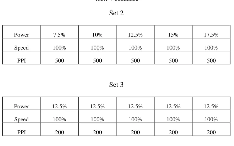
Details of laser engraving parameters are shown in the Table 3.
Table 3. Laser Engraving Parameters for Experimental Sample Preparation
Set 1
Power 7.5% 10% 12.5% 15% 17.5%
Speed 100% 100% 100% 100% 100%
33 Table 4 Continued
Set 2
Power 7.5% 10% 12.5% 15% 17.5%
Speed 100% 100% 100% 100% 100%
PPI 500 500 500 500 500
Set 3
Power 12.5% 12.5% 12.5% 12.5% 12.5%
Speed 100% 100% 100% 100% 100%
PPI 200 200 200 200 200
3.4 Laser Engraving Process
The laser engraving on the experimental samples was carried out using a UNIVERSAL
VLS6.60 laser cutter system along with the computer-controlled software called the
Universal Control Panel (UCP). The size of the lens was 2’’. The laser option was 40W CO2,
which generated a wavelength of the laser beam of 10.6 m and the power consumption was
up to 110V/10A. The process of the laser engraving treatment on the fabric surface was as
follows: (1) design the pattern using graphic design software; (2) convert the graphic pattern
to gray scale; (3) send the designed pattern to the laser software system; (4) set parameters
and conduct laser engraving treatment. Figure 6 is an image of the UNVERSAL VLS 6.60
34 Figure 6. UNIVERSAL VLS6.60 laser cutter. (2017, January 18). Retrieved from
https://www.ulsinc.com/build/manual-platform-overview on 2017, January 18.
3.5 Digital Printing Process
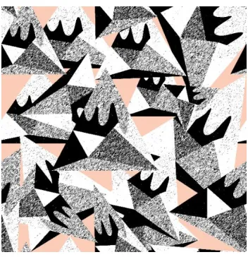
To test the effect of laser engraving on different colors, self- designed seamless pattern
was designed to print on the fabric. To learn the effects laser engraving can do upon different
color areas in digital printing. Color of orange, black, white and secondary color were
included. The digital image of the design is shown as figure 7.
35
Prior to laser treatment, the digital printing on the cotton twill fabric was carried out
using MUTOH Mc3 nano-pigment printer with Yuhan-Kimberly Nano-Pigments. The
maximum print area is 1,625 mm×1,615 mm in width × length. The print speed is 22 m²/h at
the resolution of 360 x 1080 dpi. Figure 8 is an image of the MUTOH Mc3 Nano pigment
printer. A total size of 60 inches by 100 inches of cotton twill was printed continuously with
the experimental pattern. The printed fabric was heat set by the rolling heater for 45
seconds.
Figure 8. MUTOH Mc3 Nano Pigment Printer
3.6 Testing the properties of the laser engraved digital printing fabric
In order to study the relationship between laser engraving and fabric physical properties,
several parameters that are related to the practical use of the treated fabric were tested. All
samples were conditioned under the standard atmosphere of 20.5 ± 0.5℃ and relative
humidity of 64 ± 1℃ for 24 hours before treatment and testing. Following was the
36
permeability, tearing strength, and abrasion resistance.
3.6.1 Fabric Surface Appearance
For documentation purposes, photographs of the laser-engraved digital-printed cotton
sateen fabric samples were scanned using a HP Scanjet 8300 prior to testing.
3.6.2 Color Appearance
The color appearance was measured using a Macbeth Color-Eye 7000A
spectrophotometer (Gretag Macbeth, New Windsor, NY, USA) interfaced to a digital PC
under illuminant D65, and a 10-degree standard observer. The color parameters were recorded
as spectral reflectance data in accordance with the Commission Internationale de l’Eclairage
(CIE) standard. Figure 9 shows the picture of the spectrophotometer. The corresponding
colorimetric data were obtained. ΔL* is a measure of lightness, Δa* is a measure of redness
(positive direction) or greenness (negative direction) and Δb* is a measure of yellowness
(positive direction) or blueness (negative direction) of an object. The color change (ΔE*)
between the samples treated under different settings was also evaluated. Since the observer
can only read single color, so the color data in solid orange and black areas in the
experimental samples were read and recorded. 2 measurements were averaged in both orange
37 Figure 9. Macbeth Color-Eye 7000A spectrophotometer (Gretag Macbeth, New Windsor, NY, USA)
3.6.3 Fabric Weight
The fabric weight (g) of the square laser-engraved and digital-printed samples sized 6
inches by 6 inches was measured using an electronic weight meter (GR200, A&D Company
Ltd, Japan) in according with the ASTM D 3776-07 standard. Per the standard, 2 samples
were averaged to obtain the weight of each sample. The final fabric weights (g/ m2) were
calculated using the following formulas:
Fabric weight ( g
m2) = Weighing (g) × 43.0053
3.6.4 Air Permeability
The air permeability of the fabric samples in terms of air resistance was measured with a
constant air flow at 0.04 m/s when a specimen was passed into the atmosphere using the
Frazier® Differential Pressure Air Permeability Measuring Instrument following the standard
ASTM D737-04. The evaluation results expressed as air flow (F), were recorded in
inch-pound units as ft3/min/ft2, in which a smaller value of F indicated poorer air permeability of
the fabric and vice versa. Five measurements were averaged to obtain each data point.
3.6.5 Tearing Strength
The tearing strength of the laser-engraved digital-printed cotton twill fabric samples
after laser engraving was measured with a Falling-Pendulum (Elmendorf-Type) apparatus in
accordance with ASTM D1424-96. The tear strength specimens were tested in both the warp
and weft directions. This test method covers the determination of the force required to
propagate a single-rip tear starting from a cut in a fabric and using a falling-pendulum
38
Type) apparatus. Two measurements were averaged to obtain each data point.
Figure 10. Falling-pendulum (Elmendorf - Type) Apparatus
3.6.6 Abrasion Resistance
The abrasion properties of the digital-printed cotton fabric engraved by laser were
measured according to ASTM D4966-12 with a Nu-Martindale Abrasion and Pilling Tester.
The fabrics were cut in size of 38 mm in diameter, and then with the defined load of 9 ± 0.2
kPa was rubbed against a standard abradant fabric until the samples began to have a fiber
ball. The standard abradant fabric is a plain weave, worsted wool fabric. Two experimental
samples were tested at the same time and the average was calculated as final test result.
Figure 11 shows the picture of the Nu-Martindale Abrasion and Pilling Tester.
39
CHAPTER 4 RESULTS
4.1 Fabric Surface Appearance
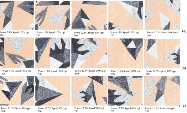
Figure 12 (a) (b) (c) shows the scanned images of the surface of digital-printed cotton
twill fabric samples engraved by the laser with different resolutions and pixel times. Under
different engraving parameters, the samples show gradual changes.
The images show that when a longer pixel time or laser power was used, there were
more fibers with pigments removed and the pattern engraved became clearer. The pigment
didn’t go all the way through the fabric, so as the surface with pigment was removed, the
original fabric color of white was revealed and the pattern engraved turned into light yellow
or white. Thus, with the increase of power and pixel times, a greater amount of laser beam
was applied to deliver energy to the fabric surface, which converted a higher percentage of
the light energy into heat. The heat vaporized more surface fibers after engraving. However,
when increasing the resolution to 500 ppi, there was no obvious change of the pattern clarity.
Also, when the laser power of 12.5% was selected, engraving patterns all appeared clearly.
Every change of 10% speed did not result in more obvious changes to the engraving patterns,
comparing to when setting the same speed and changing laser power by 2.5% each time.
What’s more, engraved patterns appeared clearly on single-colored fabric such as the orange
40 Figure 12. Scan Images of Laser-engraved Samples (a) Set 1: Speed and resolution constant, laser power changed; (b) Set 2: Speed and laser power
constant, resolution changed; (c) Set 3: Laser power and resolution constant, speed changed
(a)
(b)
(c) Power 7.5% Speed 100% ppi
200
Power 10% Speed 100% ppi
200 Power 12.5% Speed 100% ppi 200
Power 15% Speed 100% ppi 200
Power 17.5% Speed 100% ppi 200
Power 7.5% Speed 100% ppi
500 Power 10% Speed 100% ppi 500
Power 12.5% Speed 100% ppi
500 Power 15% Speed 100% ppi 500
Power 17.5% Speed 100% ppi 500
Power 12.5% Speed 90% ppi
200 Power 12.5% Speed 80% ppi 200
Power 12.5% Speed 70% ppi