Abstract
BUTTERFIELD, MATTHEW PAUL. Design and Manufacture of a Second Generation Switch-Operated Window Wall. (Under the direction of Dr. Larry M. Silverberg.)
A new system of horizontal window blinds that operates by means of electrostatic induction, called the powerblind, was developed at North Carolina State University. The blinds can be opened and closed with a simple switch. An evaluation of the
first-generation system was conducted to determine the features that needed improvement before a second-generation model could be constructed.
The problems inherent to the previous powerblind model were resolved after redesigning several parts. Eight new, fully operational powerblind units were assembled and installed in a boardroom of the Talley Student Center at North Carolina State
University in July 2006. They replaced the defective first-generation units previously located in the boardroom. A set of instructions for all the assembly and manufacturing processes was also created to facilitate the construction of additional second-generation windows.
DESIGN AND MANUFACTURE OF A SECOND GENERATION SWITCH-OPERATED WINDOW WALL
by
MATTHEW PAUL BUTTERFIELD
A thesis submitted to the Graduate Faculty of North Carolina State University
in partial fulfillment of the requirements for the Degree of
Master of Science
MECHANICAL ENGINEERING
Raleigh 2006
APPROVED BY:
_____________________________________ Dr. Larry M. Silverberg
Chair of Advisory Committee
_____________________________________ Dr. M. K. Ramasubramanian
Biography
I, Matthew Paul Butterfield, was born on July 8, 1982 in Hartford, Connecticut. I grew up in Farmington, Connecticut with my parents, Paul and Ann Butterfield, and my
sister, Sarah. A penchant for math and science fueled my desire to pursue a career in engineering at a young age. I graduated from Farmington High School in June 2000 and began my undergraduate studies at the University of Virginia in the fall of that year.
Through my curriculum in Mechanical Engineering, I developed a particular interest in the area of robotics. Upon graduation from the University of Virginia in May 2004 with a
Bachelor of Science, I enrolled in the Mechatronics graduate program at North Carolina State University. I will graduate in August 2006 with a Master’s Degree in Mechanical
Table of Contents
List of Tables ... v
List of Figures ... vi
1. Introduction... 1
2. Background Information... 3
3. First Generation Powerblind System ... 5
4. Second Generation Powerblind System... 8
5. Instructions... 15
5.1. Parts and Materials... 15
5.1.1. Air Spacers, Corner Keys, Desiccant, Insulated Glass (without wire), Mutton Keys, and Muttons ... 16
5.1.2. Aluminum Foil Electrically Conductive Tape... 17
5.1.3. Hooks ... 18
5.1.4. Insulated Glass (with embedded wire) and Uninsulated Wire... 18
5.1.5. Ladders... 19
5.1.6. Sealant... 19
5.1.7. Slats... 20
5.1.8. Tabs... 20
5.2. In House Manufacturing ... 21
5.2.1. Air Spacer and Mutton Modification... 21
5.2.2. Hook Fabrication ... 25
5.2.3. Slat Modification ... 26
5.2.4. Tab Fabrication ... 27
5.3. Assembly... 29
5.4. Installation... 41
6. Conclusions... 45
7. Works Cited ... 49
8. Appendices... 50
8.1. Wire Jig Information... 51
List of Tables
List of Figures
Figure 3.1 - Ladder/Slat/Tab Assembly... 5
Figure 3.2 - Side View of Slats and Glass in Closed and Open Positions (Gallion, 10) ... 6
Figure 3.3 - Boardroom Powerblind Units in the Closed Position (Gallion, 8)... 7
Figure 3.4 - Boardroom Powerblind Units in the Open Position (Gallion, 8) ... 7
Figure 4.1 - Film on First Generation Glass ... 8
Figure 4.2 - Sunburst Pattern ... 9
Figure 4.3 - Experimental RC Circuit... 11
Figure 4.4 - Resistor Close Up... 11
Figure 5.1 - Air Spacer, Corner Key, Mutton Key, Mutton (clockwise from top left)... 17
Figure 5.2 - Hook... 18
Figure 5.3 - Ladder ... 19
Figure 5.4 - Slats... 20
Figure 5.5 - Tabs ... 21
Figure 5.6 - Air Spacer Punch and Offset Hook Hole ... 22
Figure 5.7 - Air Spacer in Punch ... 23
Figure 5.8 - Mutton Key Holes ... 24
Figure 5.9 - Air Spacer Hole for Sealant ... 24
Figure 5.10 - Arbor Press for Hook Fabrication... 25
Figure 5.11 - Hook Die ... 25
Figure 5.12 - Slat End Punch ... 26
Figure 5.13 - Slat Hole Punch... 27
Figure 5.14 - Plastic Injection Molding Machine ... 28
Figure 5.15 - Tab Mold... 28
Figure 5.16 - Wire Wrapped Around Corner Key ... 30
Figure 5.17 - Corner Key Inserted into Air Spacer... 31
Figure 5.18 – One Corner of Frame... 31
Figure 5.19 - Completed Frame ... 31
Figure 5.20 - Foil Tape on Frame Corner ... 32
Figure 5.21 - Mutton Key Inserted into Mutton ... 32
Figure 5.22 - Mutton Key Inserted into Frame ... 33
Figure 5.23 - Foil Tape Connecting Mutton and Air Spacer ... 33
Figure 5.24 - Securing Mutton Key with Sealant ... 34
Figure 5.25 - Guide Blocks... 34
Figure 5.26 – Slat Divider... 34
Figure 5.27 - Ladder Groove ... 35
Figure 5.28 - Slats Placed in Horizontal Grooves... 35
Figure 5.29 - Ladders Placed Along Ladder Groove... 35
Figure 5.30 - Tab Secured to Ladder with Nail Set ... 36
Figure 5.31 - No Tab Inserted into Top Set of Ladder Holes ... 36
Figure 5.32 - Ladder/slat/tab Assembly in Slat Divider ... 37
Figure 5.33 - Ladder Turned 90 degrees Counterclockwise... 37
Figure 5.34 - Frame Positioned on Glass... 38
Figure 5.37 - Hook After Being Inserted into Hook Hole ... 39
Figure 5.38 - Squaring Both Pieces of Glass ... 39
Figure 5.39 - Unit Clamped Together with Spring Clamps... 40
Figure 5.40 - Sealant Applied with Caulking Gun ... 40
Figure 5.41 - Sealant Spread with Putty Knife ... 40
Figure 5.42 - Wires from Powerblind Fed Through Exterior Window Frame ... 42
Figure 5.43 - Junction Box Above One Window ... 43
Figure 5.44 - Second Generation Units in the Closed Position ... 43
1. Introduction
In recent years, there has been an increasing effort to harness the energy provided by the sun. With billions of dollars being spent annually on electricity to power artificial
lighting, there is an enormous potential for economic gain by using natural lighting solutions. In addition to the economic benefits, sunlight has many positive effects on the human body not afforded by simulated light.
Using light admitted by windows is the most obvious way to reduce the reliance on artificial light. However, the issue of controlling light that enters a room does not have a
simple solution. Today, common methods include horizontal and vertical window blinds and various types of shades and curtains. While these window coverings are adequate for small scale applications, some windows require a different solution. Conventional blinds and
shades are impossible to adjust when used with windows near high ceilings. In rooms with many large windows, such as in a commercial setting, adjusting separate blinds is a tedious
task. A new system of horizontal blinds has been developed at North Carolina State University, called the powerblind, which will remedy these problems.
The powerblind unit consists of horizontal window blinds sealed between two panes
of glass. The blinds can be opened and closed with a wall mounted switch by means of electrostatic induction. Once the preliminary design was finalized, first-generation
powerblind units were installed in a boardroom in the Talley Student Center at North
Carolina State University. Unfortunately, several problems arose with these models that had to be resolved in order for the project to proceed. Work for this thesis began by identifying
manufactured and installed in the Talley Student Center to replace the aforementioned faulty windows. These units were free of the defects present in the first-generation models.
In addition to the new windows, this thesis provides a clear and concise set of
instructions for all the manufacturing and assembly processes related to the powerblind project. Prior efforts left few records of their methods and much time and effort was wasted
2. Background Information
The positive effects of natural light on the human body have been well documented. Sunlight helps regulate many physical and mental processes. Adequate exposure improves
the body’s resistance to disease, and can aid in recover from injury and illness. Without natural light, the body does not produce enough red blood cells, which transport oxygen throughout the bloodstream. This same deficiency has been shown in the number of white
blood cells, which help fight disease, and blood platelets, which facilitate blood clotting. In addition, UV rays initiate the production of vitamin D in the skin, which allows the body to
absorb calcium and in turn, strengthen bones. A lack of exposure to sunlight can lead to sleepiness, decreased sexual desire, and depression, as more melatonin is synthesized by the pineal gland (Lillyquist, 70-101).
Today’s artificial lighting found in homes and offices is not intense enough to produce the same positive effects as sunlight. While these health issues have been well
known for decades, the country’s ever increasing energy consumption has prompted a more urgent look at reducing the reliance on artificial light sources. In 1992, the U.S. Office of Technology Assessment reported that approximately $45 billion was spent annually on
electricity used in commercial buildings alone (21). Of this total, 41 percent, or nearly $19 billion was used to provide artificial lighting (50). The most natural cost saving measure is
known as daylighting, the use of sunlight to supply sufficient illumination to an interior space (“Daylighting,” 1). This technique involves placing windows in specific locations
throughout a building to take advantage of the sun’s path above that particular building each
However, daylighting solutions are not yet commonplace in commercial or residential settings, as retrofitting buildings with the necessary technology can be quite expensive. In addition, it is difficult to precisely control the light entering a room as the angle of the sun
changes. Venetian blinds provide an acceptable solution in small rooms, but because daylighting relies on many windows that are concentrated towards the ceiling, adjusting
blinds is both time consuming and difficult (Kiefer, 229). The powerblind system under development at North Carolina State University is intended to solve these problems.
The basic principle behind the powerblind system is simple: use static electricity to
create a switch-operated set of horizontal window blinds. Dr. Larry Silverberg began work on this idea during the mid 1990s and received a patent in 1998 (Silverberg, 1). In the years
that followed, several graduate and doctoral students put the theory into practice by
producing small, sample windows with a blinds system that succeeded in opening via a light switch. The speed and ease with which it was now possible to open horizontal blinds
provided a solution to a large problem facing Venetian blinds in daylighting applications. Following the production of these successful models, electromechanical and thermal analyses were developed to confirm the system’s functionality and validity as an energy
saving design (Kiefer, 242). Manufacturing processes and tools were then prepared so larger powerblind units could be produced. In 2000, under the direction of master’s student Frank
3. First Generation Powerblind System
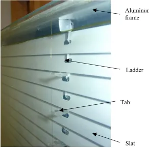
The first generation powerblinds installed in the Talley Student Center boardroom consisted of horizontal slats, the portion of the blinds that open and close, sealed between
two panes of insulated glass. The metal slats were electrically connected to an aluminum frame around the perimeter of the window by vertical “ladders.” The aluminum ladders, in conjunction with plastic “tabs,” positioned the slats appropriately between the panes of glass.
The entire assembly is shown below in Figure 3.1.
Figure 3.1 - Ladder/Slat/Tab Assembly
Powerblinds operate by means of electrostatic induction, in which an object charged with static electricity induces a charge in another object without contact between the objects. A power supply was connected directly to the aluminum frame, and a positive charge
followed the path from the frame, through the ladders, to the slats. To complete the electrical Aluminum
frame
Ladder
Tab
circuit, one pane of insulated glass had an invisible layer of tin oxide, also known as a low-e coating, which was electrically grounded. The positively charged slats were attracted
towards the electrons in the tin oxide, which gravitated towards the side of the coating closest
to the slats, putting the slats in an open position, as shown in Figure 3.2. The entire system was sealed with a silicone suitable for high voltage applications to isolate the electrical
circuit. A simple wall mounted light switch controlled the flow of electricity. With power on, the slats would open. With power off, the slats would close due to gravity. A slight offset placed the center of gravity of each slat slightly beyond the axis of rotation, allowing
them to close when electricity was not flowing.
Figure 3.2 - Side View of Slats and Glass in Closed and Open Positions (Gallion, 10)
Figure 3.3 - Boardroom Powerblind Units in the Closed Position (Gallion, 8)
4. Second Generation Powerblind System
The scope of this thesis began where the first generation system in the Talley Student Center left off. While the powerblinds in the boardroom worked well as an initial
experiment, they were still not ready for commercial production. In the spring of 2005, work began towards remedying two major problems inherent in the first generation design.
About six months after the units were installed in the boardroom, a hazy film became
visible on the surface of the glass, which can be seen in Figure 4.1. This film was found to be the tin oxide coating beading up around the areas to which the slats were continually
attracted. It became apparent that a new method of supplying a grounded glass surface was required. Instead of the low-e coating, it was determined that thin wires would be embedded in the glass to complete the electrical circuit.
Figure 4.1 - Film on First Generation Glass
Investigation into wire patterns began by simply using electrical tape to secure thin,
bare wire to the outside of one pane of glass of a powerblind window. Testing conducted by previous graduate students resulted in a preferred wire pattern, coined a “sunburst.” The
for further research into finding the ideal pattern for use in the second-generation windows for the Talley Student Center boardroom.
Figure 4.2 - Sunburst Pattern
While the “sunburst” pattern did cause the slats to open, there was no noticeable
“cascading,” as was desired. Any imperfections in the window, such as slightly different slat lengths or deformed ladders, had more of an effect on the opening of the slats than the
“sunburst” pattern. With this realization, it was determined that changing the wire pattern
was not a valid method for cascading the blinds.
The next idea was to utilize the capacitance of the blinds in combination with a
resistance to create an RC circuit that would gradually delay the opening of the blinds. The glass and slats in a horizontal position create a condition similar to a parallel plate capacitor. Estimating the gap between the glass and the open slats to be approximately 0.1 inches, the
total capacitance of the window could be calculated, as shown below.
For a simple RC circuit, the time constant, τ, is given by the equation τ =RC and
after 4τ the charge across the capacitor will be approximately 98% of the full value.
Estimating that the time for the blinds to open completely (4τ ) would be 1 second, the
resistance for the given window can be estimated.
Ω = = = = = − 7 9 10 22 . 5 ) 10 79 . 4 ( 25 . 0 25 . 0 1 4 x R x R RC s τ τ
To test this theory, the wire pattern was altered to consist of only six vertical wires, cut in three places to create four separate sections of wire. Five 10-megaohm resistors were placed between each section to delay the voltage from flowing to the top of the window.
Figure 4.3 - Experimental RC Circuit Figure 4.4 - Resistor Close Up
When powered, the bottom fourth of the slats opened immediately, with each
subsequent section opening a fraction of a second later. This arrangement opened all of the slats in a reasonable amount of time, approximately one second. With a total of fifteen
10-megaohm resistors along six vertical wires approximately 64” (5.33 ft.) in length, a necessary resistance per foot of wire was calculated.
Finding a common bare wire with a distributed resistance of approximately 168 MΩ per foot is not a possibility at this time. An alternative material, such as a semiconductor, may provide adequate resistance, but further investigation will be necessary. In order to stay
within the schedule of the Talley Student Center project, common 30 gauge tinned copper wire was chosen to be embedded in the glass.
Without the need for a cascading effect, the simplest wire pattern that would open the blinds was pursued. Vertical wires were chosen because one wire could be “hidden” if placed directly in front of a ladder. With four ladders in each window, four vertical wires
could be embedded that would be relatively unobtrusive. Four vertical wires were taped to the glass but did not open the slats completely. Additional wires were added near the ends of
the slats, in order to keep them away from the main viewing area of the window. However, the slats opened even less with the extra wires. Unusual “end effects” were created by having charged surfaces, the air spacer and mutton, next to grounded surfaces, the wires.
The benefit to aesthetics of having the wires near the edges of the glass was therefore not possible.
The next wire design consisted of the four wires in front of each ladder and one wire
located at the center of each column of slats. With two columns of slats in each window, this produced a total of six wires, three per column. This pattern eliminated any “end effects”
and divided each column of slats into four sections of approximately equal width. The distance between the ladders was roughly twice the distance from one ladder to the end of the slats, so by adding one wire halfway between each ladder, the three wires formed an
The wire design with six vertical wires per window was chosen as the pattern for the windows in the Talley Student Center because it exposed a minimum amount of wire and because of its ability to open the blinds at a reasonable voltage. Once this decision was
made, the design was sent to Arch Deco Glass in Ohio, where the wire embedding process was implemented. A wire jig was made at North Carolina State University to facilitate this
process, which was also sent to Arch Deco Glass. Information on the jig can be found in Appendix 8.1.
The second major problem with the first generation powerblinds was a particular step
in the manufacturing process. After the ladders were punched into the appropriate shape, one then had to insert the many plastic tabs used to support the slats into the ladders individually.
Because the ladders were made of thin aluminum, they bent easily when the tabs were
inserted. This deformation was plastic in nature and therefore any slight curvature resulted in a permanently misshapen ladder. If each ladder were not straight, the horizontal slats would
also be misaligned. Without the proper configuration of the ladders and slats, the blinds would not open properly. This incredibly small margin for error in the assembly of the powerblinds had to be remedied in order to make the process more efficient.
To solve this problem, a new ladder material was selected. The material had to be a metal, so as to retain the ability to conduct the necessary static electricity. It also had to be
highly elastic, so when the plastic tabs were inserted, any bending of the ladder did not result in permanent deformation. The most promising material was a shape memory alloy, or “memory metal,” called nitinol, which is a mixture of titanium and nickel. The attractive
no longer have a permanent effect. The drawbacks to the use of nitinol were its cost and machining requirements. Nitinol was more expensive than the aluminum used in the first generation ladders. It also could not be punched by hand, so a more expensive process, laser
cutting, was employed. While the cost for a small number of experimental ladders was high, once in production, the added expense of nitinol ladders would not increase the overall cost
of a window by an excessive amount. This small increase in cost was outweighed by the ability to adhere to the tight tolerances required of the manufacturing process.
Unfortunately, the relatively small amount of nitinol required for the eight windows
in the Talley Student Center was not enough for any nitinol suppliers to perform a custom run at the required size. Instead, a more readily available material, spring steel, was selected.
Spring steel was still a vast improvement over aluminum because it had a much larger elastic range. The thickness of the material was also doubled for added strength. While nitinol would theoretically be preferable to spring steel, it was simply impractical to use it in such a
small, experimental setting.
The changes to the electrical conductor in the glass and to the ladder material and manufacturing method, along with other minor changes that will be explained in subsequent
5. Instructions
This chapter acts as a detailed instruction manual for any future persons working on the powerblinds project. Included is a discussion of individual parts and their manufacturing,
as well as assembly and installation instructions.
5.1. Parts and Materials
Many of the parts and materials used in the powerblind units are identical to those used by the insulated glass (IG) industry in standard windows. The following table provides
a brief overview of the parts that make up a switch-operated window. Each part is discussed in greater detail in subsequent sections. For information regarding the ordering of parts and
materials, as well as related contact persons, see Appendix 8.3.
Table 5.1: Overview of Powerblind Components (Gallion, 9)
Part Name Function Production Method
Air Spacers Provides structural spacing between glass panes and support for sealant. Provides a path for high voltage actuation signal to hooks, ladders, and slats.
Commercially produced for IG industry. Cut to size with miter saw in lab. Holes for hooks and mutton keys punched and drilled in lab.
Aluminum Foil Electrically Conductive Tape
Provides a low resistance path for high voltage electricity between segments of air spacer and mutton.
Commercially produced for HVAC industry.
Corner Keys Connect air spacers to form the rectangular shape of the window.
Commercially produced for IG industry.
Desiccant Placed inside air spacers to absorb any residual moisture in the sealed window.
Commercially produced for IG industry.
Hooks Connect the ladder, slat, and tab assembly to the top air spacer. Provide a path for high voltage actuation signal to ladders and slats.
Table 5.1 (continued)
Part Name Function Production Method
Insulated Glass (with embedded wire)
Wire embedded within the IG attracts slats to open position with induced charge. Seals the inside of the assembly, provides insulating air space.
Commercially produced for IG industry. Specific wire pattern embedded by glass company.
Insulated Glass (without wire)
Seals the inside of the assembly, provides insulating air space.
Commercially produced for IG industry.
Insulated Wire Provides an insulated path for high voltage signal from the power supply to the air spacer.
Commercially produced for high voltage power supply industry.
Ladders Locate and support slats in air space. Provide an electrical path for high voltage actuation signal to slats.
Laser cut.
Mutton Keys Connect muttons to top air spacers. Commercially produced for IG industry. Cut to size with miter saw in lab.
Muttons Provide a separation between columns of slats in larger windows.
Commercially produced for IG industry.
Sealant Seals the inside of the assembly, provides insulating air space.
Commercially produced for high voltage power supply industry.
Slats Rotate to either block or transmit light. Commercially produced for venetian blind industry. Hole for ladders produced with manual die punch in lab. Cut to length in lab.
Tabs Locate and support ladder and slat assembly between panes of glass.
Manual plastic injection molder used in lab.
Uninsulated Wire Embedded in one pane of glass (see "Insulated Glass (with embedded wire)").
Commercially produced for electronics industry.
5.1.1. Air Spacers, Corner Keys, Desiccant, Insulated Glass (without wire), Mutton Keys, and Muttons
These parts are all donated by Arch Aluminum and Glass, located in Youngsville, NC. The insulated glass can be ordered to any specified dimensions and can be tinted upon
spacers used in the powerblinds are 3/4” wide, and the muttons are 5/8” wide. Both are modified in the lab at North Carolina State University to fit the window being constructed. Corner keys and mutton keys are made to fit the corresponding air spacers and muttons. The
desiccant comes in a granular form. Figure 5.1 shows some of these parts from Arch Aluminum.
Figure 5.1 - Air Spacer, Corner Key, Mutton Key, Mutton (clockwise from top left)
5.1.2. Aluminum Foil Electrically Conductive Tape
The aluminum tape is 1/2” wide and can be ordered from Electron Microscopy
Sciences for $28 for a 54-foot roll. Free samples can be obtained from 3M sales
improvement stores cannot be used for this application because it does not have the electrically conductive adhesive of the 3M tape.
5.1.3. Hooks
The hooks are punched in the lab at North Carolina State University from an
aluminum sheet that is 0.016” thick. The aluminum can be ordered from McMaster-Carr. A 12” x 12” sheet costs $2.78. One hook is required for each ladder. Figure 5.2 shows a sample hook.
Figure 5.2 - Hook
5.1.4. Insulated Glass (with embedded wire) and Uninsulated Wire
The wire embedding process is provided free of charge by Arch Deco Glass in Ohio. As with the glass from Arch Aluminum, any dimensions can be accommodated. To make
new wire embedded glass, Arch Deco Glass must receive a wire pattern, the corresponding wire jig, and the uninsulated wire that is to be embedded. The wire used in the second generation of windows is bare, tinned copper, 30 gauge wire from Anixter. A 1000-foot roll
5.1.5. Ladders
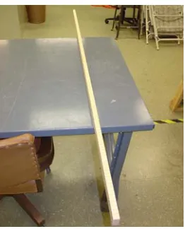
The ladders are laser cut from sheets of 0.032” thick blue tempered spring steel. The spring steel can be ordered from Industrial Spring Steel, which has a $130 minimum order.
For the eight windows at the Talley Student Center, one sheet was ordered to fit 32 ladders side by side. It should be noted that each ladder is 0.1917” wide and between 1/8” and 1/4”
of extra material must be left between each ladder to accommodate the laser cutting process. For 32 ladders, each 64” long, sufficient material was purchased for the minimum order amount.
The spring steel is shipped directly to Advanced Laser to be cut. Cutting services for the 32 ladders was approximately $1200. The bottom portion of a finished ladder can be
seen in Figure 5.3 below.
Figure 5.3 - Ladder
5.1.6. Sealant
The GE high voltage sealant comes in a five-gallon bucket and in 10-ounce caulk cartridges. The sealant in the bucket (RTV5812) is white, while the sealant that comes in
second-generation windows because of the easier application process. The clear sealant is simply applied with a caulking gun. When purchasing the sealant, note that one cartridge is required for approximately 100” of air spacer length.
5.1.7. Slats
Slats are purchased from AAA Blind Manufacturing and can be ordered in various lengths and colors. Approximately 2250 slats were ordered for the eight windows at the Talley Student Center, which cost $500. Slats are cut to length and holes for the ladders are
punched in the lab at North Carolina State University. Several slats can be seen in Figure 5.4 below.
Figure 5.4 - Slats
5.1.8. Tabs
Tabs are manufactured in the lab at North Carolina State University by means of a plastic injection molding machine. The polypropylene pellets used in the injection molder are donated by Aimet Technologies in Raleigh. Several tabs are pictured in Figure 5.5
Figure 5.5 - Tabs
5.2. In House Manufacturing
Some parts require modification in the lab, while others are manufactured entirely at North Carolina State University. Related instructions are provided in the following sections.
An important tool that helps in determining the necessary quantity of parts and their
sizes is a preexisting excel file. By inputting the desired window size, glass width and height, the excel file automatically computes the number of slats, the lengths of the muttons,
air spacers, and slats, as well as the positions of various holes that must be punched. The glass sizes used in the Talley Student Center can be found in Appendix 8.1.
5.2.1. Air Spacer and Mutton Modification
Materials Required: Aluminum air spacers
Aluminum muttons
Primary Tools Required: Miter saw
Drill press (with 5/64” and 1/4” drill bits) Air spacer punch
Air spacers and muttons must first be cut to the length dictated by the size of the
This eliminates a potential failure mode because everything inside the air spacers now hangs freely, and therefore parallel, decreasing the chances of contact between the slats and the mutton.
While muttons must only be cut to length, the air spacers require further modification. The top air spacer of each window has to have holes from which to hang the ladders and any
muttons. It is important that all holes are punched or drilled on the correct side of the air spacer. One side is smooth, while the other side, the side where the holes should be, has a series of indentations along the centerline.
The ladders are attached to the top air spacer by aluminum hooks. The hook holes are punched with the air spacer punch, shown in Figure 5.6 below, at distances dictated by the
excel worksheet. The nature of the ladder design requires that the hook holes be offset from the centerline of the air spacer. The punch accounts for this offset, which can also be seen in the air spacer in Figure 5.6.
There is another offset present in the punch design. The distance between actual cutting piece and the edge of the punch housing is one inch. This means that if one were to slide the air spacer to the edge of the punch housing, as in Figure 5.7, the hook hole would be
punched exactly one inch from the end of the spacer. Therefore, to punch a hole, for example, four inches from the end of the air spacer, one would mark the spacer at three
inches, slide the spacer until the line is at the edge of the punch housing, and punch the hole.
Figure 5.7 - Air Spacer in Punch
The muttons are attached to the top air spacer by a mutton key. Holes are drilled in the air spacer to accommodate the two-pronged end of the mutton key, which can be seen in Figure 5.8. The excel spreadsheet provides the location of the mutton holes in relation to the
end of the air spacer, but it does not specify the location of the holes along the width of the spacer. The distance between the two prongs of the mutton key is 1/2”, while the spacer is
Figure 5.8 - Mutton Key Holes
When drilling the mutton holes, use the drill press in the lab with a 5/64” drill bit.
The holes will be slightly smaller than the diameter of the prongs, so an awl should be used to enlarge them just enough to allow the prongs to be press fit in the holes.
One final hole must be drilled in the air spacer, directly opposite the two mutton
holes, on the smooth side of the spacer. This hole, shown in Figure 5.9, is 1/4” in diameter and is centered along the width of the spacer. It is used to insert a small amount of sealant
into the air spacer during the assembly process to secure the mutton key.
5.2.2. Hook Fabrication
Materials Required: 0.016” thick sheet of Aluminum Primary Tools Required: Arbor press
Hook die
Hooks are manufactured in the lab at North Carolina State University. The press in Figure 5.10 is used in conjunction with the hook-shaped die shown in Figure 5.11 to cut the
aluminum hooks.
Before operating the press, the sheet of aluminum is cut into strips wide enough to accommodate one hook. A box cutter and a straight edge will suffice for this procedure.
Next, one strip of aluminum is placed in the die and the press handle is lowered. After the hook is punched from the strip, excess aluminum remains caught on the die. It can be
removed with a pair of pliers.
5.2.3. Slat Modification
Materials Required: Slats
Primary Tools Required: Slat end punch Slat hole punch
Two modifications must be made to the slats before they are ready for assembly. First, they must be cut to the appropriate length given in the excel worksheet. The slat end
punch, pictured in Figure 5.12 below, trims and rounds the ends of the slats. The guide on the punch is used to provide a mechanical stop for the slat at a fixed distance away from the cutting tool. It is important to trim both ends of each slat so both are rounded. Therefore, the
guide should be set to half the length of the amount to be trimmed. For example, if a particular slat is 18” long, and the desired length is 16”, the guide should be set to trim 1”.
Then, both ends of the slat will have 1” removed and both will have rounded ends.
Figure 5.12 - Slat End Punch
The second step in the slat modification process is punching the ladder holes. The slat hole punch, seen in Figure 5.13, functions in the same manner as the slat end punch. A guide can be positioned to provide the mechanical stop for the slat at any point. The distance
from the end of the slat to the slat hole center can be found in the excel spreadsheet. Once the guide is locked at the appropriate location, both holes can be punched using that position
Figure 5.13 - Slat Hole Punch
5.2.4. Tab Fabrication
Materials Required: Polypropylene pellets
Primary Tools Required: Plastic injection molding machine
Air compressor
Tab mold
The plastic injection molding machine pictured in Figure 5.14 melts polypropylene
Figure 5.14 - Plastic Injection Molding Machine
Figure 5.15 - Tab Mold
To begin the fabrication process, the injection molder is plugged into an outlet and
into an air compressor. This allows the operator to control two parameters: temperature of the chamber and pressure of the plunger. Optimum temperature and pressure have been
found to be approximately 500 degrees Fahrenheit and 60 psi, respectively. The chamber is immediately filled with pellets to prevent any burning. Once the appropriate temperature is
Air
Connection
Pellet Chamber
reached, the operator purges the chamber in order to eliminate any leftover burnt and
discolored plastic by holding the control button for the plunger until clear plastic flows from the injection molder.
At this point, the mold is opened and the inside is sprayed with a silicone mold releaser. The mold is then closed and placed in the vise of the injection molder, with one of
the holes of the mold aligned with the exit nozzle of the injection molder. To position the mold directly beneath the nozzle, pieces of metal are used as spacers behind the mold. Care must be taken to ensure that the vise is as tight as possible to prevent leakage of the plastic
within the mold. Next, the operator holds the plunger control button until a small amount of plastic seeps out of the hole on the mold. The mold is then moved so that the other hole can
be filled. To remove the completed tabs, the mold is reopened and needle-nosed pliers are used to pull the tabs from the mold. Excess plastic can sometimes seep out from the mold and must be trimmed to produce acceptable tabs. Keeping the mold clamped tightly in the
vise will limit this problem.
When repeating this process, the silicone mold releaser should be sprayed on the mold before each batch of ten tabs. The operator should also refill the pellet chamber
completely after each batch. Tab quality will improve as the temperature of the mold increases through repeated use.
5.3. Assembly
The following is a step-by-step list of instructions for assembling one powerblind
accidentally sealed inside the window. If possible, have a previously constructed powerblind unit present with which to compare during the assembly process.
Frame Assembly: Required Parts:
• (4) Aluminum Air Spacers (of appropriate lengths) • (1) Insulated Wire (approximately three feet long) • (4) Corner Keys
• Muttons (if necessary) • Mutton Keys (if necessary) • Aluminum Foil Tape • Desiccant
• Sealant
1. Strip about two inches of insulation off one end of the wire.
2. Wrap the bare end of the wire around one corner key, as shown below. This will establish an electrical contact between the wire and the top air spacer.
Figure 5.16 - Wire Wrapped Around Corner Key
3. Insert the end of the corner key with the bare wire into one end of the top air spacer, as pictured below. Push the corner key all the way into the air spacer. Be sure the air spacer is oriented correctly. The series of indentations along the centerline, as well as
Figure 5.17 - Corner Key Inserted into Air Spacer
4. Connect the remaining aluminum air spacers and corner keys to form the rectangular
frame, as depicted below. Be sure the sides of the air spacers with the indentations all face toward the center of the frame. During this process, completely fill the two vertical air spacers with desiccant.
Figure 5.18 – One Corner of Frame Figure 5.19 - Completed Frame
5. Apply aluminum foil tape around the outside corners of the frame, electrically
Figure 5.20 - Foil Tape on Frame Corner
6. If a mutton is necessary (see excel spreadsheet), insert a mutton key into one end of
the mutton in the manner shown in the picture below.
Figure 5.21 - Mutton Key Inserted into Mutton
7. Insert the other end of the mutton key, the two-pronged end, into the predrilled holes in the top air spacer, as shown below. The mutton key will be press fit, and the
Figure 5.22 - Mutton Key Inserted into Frame
8. Apply aluminum foil tape, as depicted below, to electrically connect the top air spacer
with the mutton. Place a piece of tape on both sides of the mutton.
Figure 5.23 - Foil Tape Connecting Mutton and Air Spacer
9. Using a caulking gun, fill the hole on the opposite side of the air spacer with a small amount of sealant, as shown below. Use enough sealant to completely cover the
Figure 5.24 - Securing Mutton Key with Sealant
Blind Assembly:
Required Parts: • Ladders • Slats • Tabs
• (2) Guide Blocks
Figure 5.25 - Guide Blocks
• (1) Slat Divider
1. Place the two guide blocks side by side, with the “T” towards the top of the ladder and the “B” towards the bottom. Clamp the guide blocks to the edge of the table where the assembly is taking place.
2. Place 2 slats in each horizontal groove of the guide blocks, as shown below. The slats should span both guide blocks, with the slat holes lining up with the ladder grove.
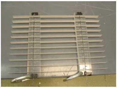
3. Slide a ladder along the ladder groove of each guide block, passing it through the aligned slat holes, as illustrated in the figure below.
Figure 5.29 - Ladders Placed Along Ladder Groove
Figure 5.27 - Ladder Groove Figure 5.28 - Slats Placed in Horizontal Grooves Ladder
groove
4. Insert a tab into each corresponding opening in the guide blocks. Part of the tab will pass through the holes in the ladder. Use a hammer and a nail set or punch, similar to the one pictured below, to ensure the tab is secured to the ladder. DO NOT insert a
tab into the top set of ladder holes. These holes will be used to attach the ladder to the top air spacer using a hook.
Figure 5.30 - Tab Secured to Ladder with Nail Set
Figure 5.31 - No Tab Inserted into Top Set of Ladder Holes
5. Carefully remove the ladder/slat/tab assembly from the guide blocks. For windows
with ladders longer than the length of the guide blocks, place the tabs that were removed from the bottom opening of the guide blocks into the top opening and repeat
steps 1-4 as needed. Instead of inserting the slats into the horizontal grooves of the guide blocks first, align the ladders in the ladder grooves and then slide the
appropriate number of slats onto the ladders from the bottom. At this point, the slats
can be placed in the horizontal grooves as described in step 2.
6. Set the ladder/slat/tab assembly in the slat divider, separating the slats so that one slat
rests in each slot of the slat divider, as in the figure below.
Figure 5.32 - Ladder/slat/tab Assembly in Slat Divider
7. Turn both ladders 90 degrees counterclockwise, so that the slats rest properly on the
ladders, as illustrated below.
Figure 5.33 - Ladder Turned 90 degrees Counterclockwise
Attach Blind Assembly to Frame: Required Parts:
• (1) Insulated Glass (with embedded wire) • (1) Insulated Glass (without embedded wire) • Hooks
1. Place the piece of insulated glass with wire on a clean table. Clean the surface of the glass facing up (which will be on the interior of the unit) with glass cleaner.
2. Center the previously assembled frame on the piece of glass. The insulated wire
should be at the top of the window. The hook holes in the top air spacer should be located on the side of the centerline furthest from the piece of glass with the
embedded wire, as pictured below.
Figure 5.34 - Frame Positioned on Glass
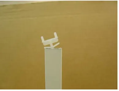
3. Attach a hook to each ladder as shown below. The lower tab of the hook is inserted through the ladder hole closest to the air spacer and is bent around the ladder.
Figure 5.35 - Hook Attached to Ladder
4. Remove the ladder/slat/tab assembly from the slat divider and place it on the piece of
be positioned at the top of the window. Insert the upper tab of each hook into the appropriate hook hole in the top air spacer, as pictured below.
Figure 5.36 - Hook Before Being Inserted into Hook Hole
Figure 5.37 - Hook After Being Inserted into Hook Hole
5. Clean the piece of glass without the embedded wire with glass cleaner and then place it on top of the frame. Using a combination square, square the two pieces of glass so the edges of both pieces are even, as seen below. Be sure the frame is still centered
on the glass.
6. Clamp the unit together using spring clamps, as seen below. Test the unit to be sure it is functioning properly.
Figure 5.39 - Unit Clamped Together with Spring Clamps
7. Using a caulking gun and putty knife, apply sealant around the entire perimeter of the unit, as illustrated below. Be sure to use the putty knife to fill the entire area between
the air spacer and the edges of the glass. Do not leave any air pockets.
Figure 5.40 - Sealant Applied with Caulking Gun Figure 5.41 - Sealant Spread with Putty Knife
5.4. Installation
The following are instructions for installing a powerblind unit in the Talley Student Center boardroom at North Carolina State University. While some of the information is
specific to that particular application, installing a powerblind unit elsewhere follows the same basic procedure.
Note on the electrical wiring in the boardroom:
The switch by the main door of the boardroom operates all eight powerblind units.
There is a box above the ceiling tiles directly above the switch that controls the 110 V AC. A relay plugs into this box, providing an easy way to kill the power to the blinds. The 110 V
AC runs across the room to an outlet above the ceiling tiles near the rightmost window. A variable high voltage power supply, which is also mounted near the rightmost window, runs off of the 110 V outlet. This power supply provides the high voltage electricity used to open
the blinds. The optimum voltage for the boardroom was found to be 3.75 kV. There is a junction box installed above each powerblind unit. One positive and one ground wire run from the power supply to the nearest junction box. Another set of positive and ground wires
runs from that junction box to the next in line. This arrangement repeats through the series of eight junction boxes.
1. Remove any existing glass and framing material.
2. Set the powerblind unit in the exterior window frame. Place thin, foam padding around the perimeter of the powerblind unit so it does not rest on the metal window
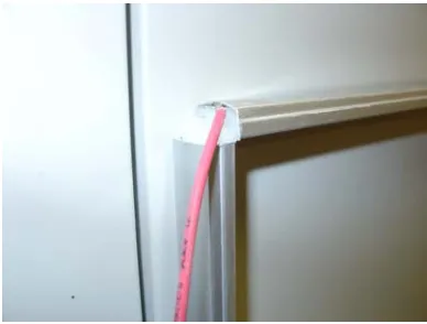
3. Feed the positive wire connected to the aluminum spacer frame through the hole in the exterior window frame, as shown below. Do the same with one end of the horizontal wire embedded in the top of the glass, which acts as a ground.
Figure 5.42 - Wires from Powerblind Fed Through Exterior Window Frame
4. Secure the powerblind unit in place with the appropriate framing material.
5. Feed the two wires from the powerblind unit into the junction box above the window. Connect all three positive wires (one from the junction box to the right, one going to
Figure 5.43 - Junction Box Above One Window
6. Put the cover on the junction box. Return any ceiling panels that were moved during
the installation.
Below are photographs of all eight powerblind units installed in the Talley Student Center boardroom.
6. Conclusions
The ultimate goal of the powerblinds project was to produce a cost effective method to quickly and easily control large-scale window blinds. By relying predominantly on
preexisting parts from the insulated glass industry, the windows were quite economical. A complete price list can be found in Appendix 8.2. Work on the second-generation system focused on incorporating several improvements to the final design.
One major change was using thin, embedded wire to facilitate the electrostatic induction, rather than the tin oxide coating from the first-generation windows. This
eliminated the possibility of the film reappearing in the new units. A particular wire pattern was chosen to minimize the appearance of the wire, while still providing sufficient
electrostatic force to open the slats completely.
The other critical modification implemented in the second-generation powerblinds was the use of a new ladder material and a new process for manufacturing the ladders. The
requirements for this material were that it conduct electricity and deform elastically.
Ultimately, spring steel was chosen for the ladders. The original ladder punch in the lab was designed to cut the ladders from aluminum, and therefore could no longer be used to punch
the spring steel ladders. Laser cutting provided an accurate method of manufacturing the ladders from the spring steel. The spring steel ladders did not deform permanently at all
during the assembly process and relatively little care had to be employed when handling these new ladders.
Several other minor changes were made to the manufacturing and assembly processes
end punch not only trimmed the slats to length, but also rounded the edges of the slats slightly. This curvature can be seen in Figure 5.4. Rounding the edges prevented the slats from sticking to the vertical air spacers or muttons when making contact with them in the
window.
The first generation windows were also assembled without the aid of the guide blocks
or the slat divider. Instead, the tabs were inserted individually, by hand, into the appropriate holes in the aluminum ladder. Because of the nature of the aluminum, the insertion of each tab would have caused the ladder to deform locally. Without the slat divider, each slat had to
be carefully positioned to allow the 90-degree rotation.
All of the aforementioned improvements not only led to a superior set of windows,
but also greatly reduced the production time. Frank Gallion, the master’s student in charge of the first generation system, noted that two workers assembled the final unit in two hours (Gallion, 6). The final second generation unit was assembled in approximately one hour by
two workers.
One problem did arise upon installing the second generation units. Random slats experienced a slight “flutter,” or shake at higher voltages. The power supply in the
boardroom was set to 3.75 kV to eliminate this activity. However, a higher voltage, such as 10 kV, is preferable, as the slats would open faster, but the fluttering motion was too
distracting at voltages above 3.75 kV. Various external sources are potential causes of this problem. The frame of the powerblind is completely separated from the outside environment by the high voltage sealant and the pane of wire embedded glass is grounded. However, the
embedded wire and the ground of the surroundings could cause the slight fluttering effect. It is also possible that the steel window frames need to be grounded.
Once this issue of fluttering is addressed, it is expected that the powerblinds project
will have reached a point in which commercial production is possible. The two major defects of the first-generation windows have been remedied and it may be that further improvements
would be best completed in industry.
First, spring steel may not be the definitive solution to the problem of deformed ladders. While it is a tremendous improvement, nitinol remains a more elastic material. It
was not financially possible to use nitinol in such small quantities in this experimental setting, but if the powerblinds were in commercial production, nitinol could be purchased to
the desired specifications. However, the cost of nitinol is approximately ten times that of spring steel in small quantities. Unless there is a significant discount for ordering a large amount of nitinol, spring steel may still be the most practical option in production.
Second, if a manufacturer wanted to pursue the cascading effect of the slats, the research already presented could be used to find a wire with the appropriate distributed resistance. The same pattern used in the Talley Student Center windows could still be used,
replacing the 30 gauge tinned copper wire with the resistive wire.
In addition to potential commercial production, variations of the rectangular, vertical
powerblinds are currently being researched at North Carolina State University. Adaptations for atypical window sizes, such as half rounds, are being examined. Skylights, both
horizontal and angled, also have the potential for modification to house powerblinds.
However, electromechanical and heat transfer analyses have been performed that have shown that automation is possible. A control algorithm for the slats could be implemented to
optimize daylighting and heat transfer (Kiefer, 231-241).
With the advent of automated slats, a project on a grand scale is highly encouraged. For example, preliminary brainstorming on a geodesic dome that uses powerblinds has been
7. Works Cited
“Daylighting.” U.S. Department of Energy. 13 June 2006. http://www.eere.energy.gov. Gallion, Franklin Cordell. “ Manufacture and Field Test of a New Adaptive Shading
Product: A Case Study.” Master’s Thesis, North Carolina State University, 2001. Kiefer, Scott F., Larry M. Silverberg, and Manoel L. Gonzalez. “Electrostatically actuated
window blinds.” Journal of Electrostatics. 50 (2001): 229-248.
Lillyquist, Michael J. Sunlight and Health. New York: Dodd, Mead & Company, Inc. 1985.
Silverberg, Larry M. “Electrostatically Positioned Blind Insert for Insulated Glass.” U.S. Patent No. 5,850,861. December 22, 1998.
U.S. Congress, Office of Technology Assessment. Building Energy Efficiency. Washington,
8.1. Wire Jig Information
The following instructions relate to the eight windows built for the boardroom at the Talley Student Center.
Items Shipped to Arch Deco Glass:
• 4’x 6’ MDF (3/4” thick) with 32 holes drilled for roll pins
• roll pins
• molding to protect roll pins
• wire to be embedded in glass
Wire Jig Assembly Instructions:
The jig contains 32 predrilled holes in the piece of MDF. The holes have been drilled to allow slightly less than ¼” of the roll pin to stick out of the MDF, as requested. The roll
pins have not been inserted into the MDF in order to protect the jig during shipping. The roll pins are easily inserted into the holes with a rubber hammer. They can be removed with a
pair of pliers.
Glass to be used:
Eight pieces of glass embedded with the included wire are needed. There are two
different sizes of glass required. The dimensions are given below:
• 34” x 63 ¾” (6 pieces needed)
Wiring Instructions:
Please see attached drawings for wire layout.
Due to the different dimensions of the glass, the wiring of each size is slightly
different. When wiring the bigger glass, only insert roll pins in the holes that have been circled with blue marker. An outline of the four corners of the bigger glass has also been
drawn in blue marker on the MDF to show where the glass should be placed. Once the roll pins and glass are in place, the wire can be strung. The vertical wires should be run on the left side of the roll pins and the horizontal wires on the bottom side of the roll pins, as shown
in the attached drawings. When the wiring is complete, the included molding can be placed next to the roll pins, with the lip overhanging the pins for protection. Use the two longer
pieces of molding on the top and bottom of the glass (the shorter dimension) and place the four small pieces so that they cover each of the four roll pins used to string the horizontal wires. This process is repeated for the smaller glass using the red markings instead of blue.
Also, please leave about an inch of wire sticking out of the glass everywhere after it is removed from the oven.
Important:
• Run vertical wires on left side of roll pin
Jig Information:
• ¾” MDF (medium density fiberboard)
• 1/8” diameter, 5/8” length roll pins (also called spring or tension pins)
• holes in MDF are slightly deeper than 3/8”, leaving slightly less than ¼” of roll pin
sticking out of MDF, as requested by glass manufacturer • Wire should also be sent to Arch Deco Glass
Ship MDF to Arch Deco Glass at NCSU shipping and receiving located at 3240 Ligon
8.2. Price List for Talley Student Center Windows
Part/Process Amount of Material (if applicable) Estimated Cost
Ladder material 65" x 12 3/8" x 0.032" sheet $130.00
Ladder fabrication $1,200.00
Window sealant 24 tubes $329.49
Hooks ~200 hooks $2.78
Metal tape 54 feet $28.00
Wire to be embedded in glass 1000 feet $75.00
Medium density fiberboard and hardware for wire jig $90.66
Slats ~2200 slats $500.00
Wire embedding free
Polypropylene pellets for tabs free
Corner Keys free
Mutton Keys free
Aluminum air spacers free
Muttons free
Glass free
Desiccant free
8.3. Contact Information
Company Contact Person
Phone Number
Fax Number Address Email/website Function
3M Larry Yates 512-984-5458 [email protected] Larry is a sales rep for 3M and can provide samples of the electrically conductive tape (Part # 1120 or 1170, 1/2" wide)
Arch Deco Glass
Mike Blankenship
614-876-1057 614-351-0211 2395 Setterlin Drive Columbus, OH 43228
[email protected] makes wire embedded glass
AAA Blind Manufacturing
Manny
Montoya, Polly
919-380-0898 955 N. Harrison Ave. Cary, NC 27513
supplies slats in various
lengths and colors; ~$500 for 2250 slats
Advanced Laser
Lester Gragg and Rick
408-436-7240 408-441-8834 1707 Rogers Avenue, Unit A
San Jose, CA 95112
www.adv-laser.com/ [email protected]
provides laser cutting services for ladders
(~$1200 for 32 ladders, 64" in length)
Aimet
Technologies
919-876-9340 919-876-9760 4200-121 Atlantic Avenue Raleigh, NC 27604
http://www.aimet.com/ [email protected], [email protected], [email protected]
supplies polypropylene pellets for plastic injection tabs
Anixter Pete 919-380-3290 Pete's direct line: 919-463-1086
919-463-1093 120 Trans Air Drive Morrisville, NC 27560
www.anixter.com supplies wire that is embedded in glass from Arch Deco Glass; bare, tinned copper, 30 gauge, $58/1000 feet
Arch Aluminum and Glass
Gerald Ashley 800-830-2044 800-934-6296 400 Park Avenue Youngsville, NC 27596
Electron Microscopy Sciences http://www.emsdiasum.com/microsc opy/products/sem/conductive.aspx# 77800 supplies electrically conductive tape (Part #77799) 1/2" wide, 54 feet long, $28
Fastenal 919-465-2399 919-465-9438 424 Airport Boulevard Morrisville, NC 27560
http://www.fastenal.com/web/produc ts/detail.ex?sku=64077
supplies roll pins (1/8" diameter, 5/8" length) $0.03 each
Hisco Jim Danku Rick Etters
Jim (cell): 919-608-8819 Rick (office): 919-572-5100
5243 Capital Blvd Raleigh, NC 2933 S. Miami Blvd Durham, NC 27703
http://www.hiscoinc.com/ supplies sealant; RTV5812 (5 gallon bucket, white) or RTV5818C (10 oz cartridge - $12 each, clear)
Industrial Spring Steel
Brian Smith 215-426-7000 215-426-7003 2656 N. Salmon St. Philadelphia, PA 19125
www.industrialspringsteel.com [email protected]
supplies spring steel for ladders (0.032" thick sheets, $130 minimum order)
K.A.M. Tool and Die
919-269-5099 919-269-5709 530 Industrial Drive Zebulon, NC 27597
www.kamtool.com [email protected]
made die for 1st generation ladders
McMaster-Carr
404-346-7000 6100 Fulton Industrial Blvd. Atlanta, GA 30336
www.mcmaster.com [email protected]
supplies aluminum sheet metal for 1st generation ladders and hooks; 0.016" thick, part # 8973K16 (comes in 12"x12", 12"x24", 24"x36", 36"x48", 36"x96")
NCSU Shipping and Receiving
Sherwood 919-515-9464 3240 Ligon Street Raleigh, NC
ships MDF to Arch Deco
Glass
NDC - Nitinol Devices & Components
Cynthia Lai 510-498-1877 510-623-6995 47533 Westinghouse Drive Freemont, CA 94539
Talley Student Center
Marie Ministero, Randy Colby, Evelyn Reiman
Marie (office): 919-515-1091 Marie (cell): 919-255-0676 Randy: 919-513-3451 Evelyn: 919-515-7117
Marie: [email protected] Randy: [email protected] Eveyln: [email protected]