ISSN(Online): 2320-9801
ISSN (Print): 2320-9798
I
nternational
J
ournal of
I
nnovative
R
esearch in
C
omputer
and
C
ommunication
E
ngineering
(An ISO 3297: 2007 Certified Organization)
Vol. 4, Issue 4, April 2016
A Review on Design and Implementation of
Numerically Controlled Oscillator
Arti D. Gaikwad1, Govind U. Kharat2, Shekhar H. Bodake3
P.G. Student, Dept. of E&TC, SP College of Engineering, Otur, Pune, Maharashtra, India1
Professor, Dept. of E&TC, SP College of Engineering, Otur, Pune, Maharashtra, India2
Assistant Professor, Dept. of E&TC, SP College of Engineering, Otur, Pune, Maharashtra, India3
ABSTRACT: Numerically Controlled Oscillator (NCO) is asignificantcomponent in many Digital Communication Systems such as Digital Radio set and Modems, Software Defined Radios, Digital Down/Up converters for Cellular and PCS base stations etc. A common method for digitally producing a complex or real valued sinusoid employs a Look-Up table based scheme. The NCO Design is first simulated and enhanced on the software tool Xilinx 12.1 and then coded in VHDL for Hardware Realization. The Designs are tested on Xilinx Spartan3 FPGA Development Platform. The test results are matching with theoretical and simulated results. A FPGA-based Implementation method which can greatly improve the performance, shorten development cycle and reduces cost. The design is implemented using the Enhanced Direct Digital Synthesis (DDS) Technology. The basic NCO architecture is enhanced with the minimum hardware to facilitate the complete system level support for different kinds of modulation with minimal FPGA resources. The size of the ROM look up is reduced by using mapping logic.
KEYWORDS: NCO, DDS, DDFS, LUT, Xilinx, Spartan 3 FPGA
I. INTRODUCTION
A key requirement in most applications is the ability to produce& control waveforms at various frequencies. Advantages of Numerically Controlled Oscillators over other types of oscillators in terms of agility, precision, stability &reliability.The Direct Digital Synthesis (DDS) technique is become popular & gets accepted by industrial community to achieve programmable analog outputs with accuracy & high resolution.NCO is latest technology of Frequency synthesis which is developed using 3rd generation of Frequency synthesis technology. The method of NCO is become popular as a method of sinusoidal signal generator & signals in digital systems modulator [2]. NCO is an important component in many Digital Communication Systems such as Digital Radios & Modems, Software Defined Radios, Digital Down/Up converters for Cellular & PCS base stations etc.
ISSN(Online): 2320-9801
ISSN (Print): 2320-9798
I
nternational
J
ournal of
I
nnovative
R
esearch in
C
omputer
and
C
ommunication
E
ngineering
(An ISO 3297: 2007 Certified Organization)
Vol. 4, Issue 4, April 2016
Fig.1 Conventional digital sinusoid generation (Architecture 0).
In DSP systems, nonlinear functions, such as trigonometric, square root or Bessel functions are frequently encountered. There are several solutions to this problem, for instance, using a CORDIC core, or look-up tables (LUTs). A great deal of effort is expended to optimize LUTs to maintain the precision required, whilst minimizing the actual size ofthetable.For some functions, an existing approach is to utilize hierarchical LUTs. In this work, we present a numerically controlled oscillator (NCO) - sometimes referred to as a direct digital frequency synthesizer (DDFS) - using a LUT and a linear approximation circuit for the generation of the sine wave values in between the entries ofthe LUT [3].
Today's advanced DDFS solutions are fast becoming an alternative to traditional analog synthesizers. The main advantages ofa DDFS system are[3]:
Micro-Hertz tuning resolution of the output frequency and sub-degree phase tuning capability.
Extremely sudden "hopping speed" with continuous phase.
No manual system tuning as in analog systems.
Unparalleled matching and control of I and Q signals in a quadrature synthesizer.
The conventional digital sinusoid generation in a NCO,referred to as Architecture 0, is presented in Fig. 1. In this system, there are several sources of spurious frequencies. Firstly, the precision of the samples stored in the LUT creates a noise floor corresponding to the number of bits used for storing the samples. If the NCO is followed by thedigital-to-analog converter (DAC), the precision of the converter further limits the signal-to-noise ratio (SNR). The influence of the DAC will not be considered further in this paper. In the digital domain, this quantization noise can be at least partially suppressed by dithering [3]. The second and most dominant source of spurious frequencies, severely limiting the spurious free dynamic range (SFDR) is the truncation of the phase word related to the size limit of the LUT. Because both the phase and amplitude samples are periodic sequences, their restricted word length representations contain periodic error sequences, which cause spurs. The spur signal level in Architecture 0 is approximately 6 dB per bit of representation below the amplitude of the desired sinusoidal signal. Example output spectra of Architecture 0 are shown in Fig. 2 for the LUT with II-bit and 12-bit address spaces (in both cases truncated from the 16-bit phase register). As expected, the improvement in SFDR is 6 dB [3].
II. RELATED WORK
In 2002 [1] authors used hybrid function generation for sine wave generation scheme for high-precision NCOs, which combines traditional LUTs with the iterative procedures of the CORDIC algorithm.No technology-specific ROM generators were required to implement this area and power efficient NCO architecture.Hybrid architectures together with a technology independent HDL description may be used to derive high-performance, high-precision DDFS systems, with fullportability for unrestricted and technology independent NCO cell reuse.
In 2015 [2] Using the Numerically Controlled Oscillator (NCO) module to generate a sine wave at any desired frequency and its advantages over the conventional Pulse-Width Modulation (PWM) approach have also been covered. The use of the NCO is not limited to the generation of a sine wave. By using a proper filter with an appropriate cutoff frequency, any desired wave shape can be rendered to the resultant output.
ISSN(Online): 2320-9801
ISSN (Print): 2320-9798
I
nternational
J
ournal of
I
nnovative
R
esearch in
C
omputer
and
C
ommunication
E
ngineering
(An ISO 3297: 2007 Certified Organization)
Vol. 4, Issue 4, April 2016
the gain.
In 2013 [5] this include the simulation and Implementation of NCO. The Design and Realization of NCO include sub modules like phase Accumulator and Look-Up Table. Area resources are optimized by using Coefficients for only quarter cycle of sinusoidal waveform and for remaining part the same has been flipped and for negative cycle it has been inverted.
In 2013 [6] Authors used Direct Digital Synthesizer is done at tuning frequency which is specified as normalized value relative to clock rate given. Since it is dual Oscillator, hence it support variable Width, Phase modulation inputs and user defined frequency resolution.
III. OVERVIEWOFNCO
A. Architecture of NCO
In the simplest case, Numerically Controlled Oscillator is constructed by a ROM with samples of a sine wave stored in it (sine look-up, LUT) [5]. Fig.2 shows the block diagram of a NCO system. The NCO produces sinusoidal signals at a certain frequency setting word (FSW) which determines the phase step. Once set, this digital word determine the sine wave frequency to be produced. The phase accumulator output than continuously produces proper binary words representing the instantaneous phase to the table look-up function[2].
Fig.2 Block Diagram of a NCO system
In other words, the phase accumulator is used to “calculate” the successive addresses of the sine look-up table, which generates a digital sine-wave output. In this way, the samples are swept in a controlled manner i.e. with a step depending on the Frequency Setting Word. The NCO translates the resulting phase to a sinusoidal waveform via the look-up table, and converts the digital representation of the sine-wave to Analog form using a Digital-to-Analog converter followed by a low pass filter (LPF) [2].
The digital part of the NCO consists of the phase accumulator and the LUT. The frequency of the output signal for signal N-bit system is determined by following equation
= ×
Where K is the FSW,
N is the number of bits that the phase accumulator can handle Fclk is system clock [5].
IV. DIRCTDIGITALSYNTHESIZER
ISSN(Online): 2320-9801
ISSN (Print): 2320-9798
I
nternational
J
ournal of
I
nnovative
R
esearch in
C
omputer
and
C
ommunication
E
ngineering
(An ISO 3297: 2007 Certified Organization)
Vol. 4, Issue 4, April 2016
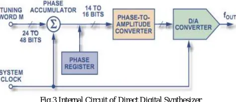
Fig.3 Internal Circuit of Direct Digital Synthesizer
Fig. 3 shows the internal components of Direct Digital Synthesizer. Its main components are Phase accumulator it means that phase to amplitude conversion & DAC [12].
A DDS output produce a sine wave at a given frequency. The frequency depends on two variables are the Reference Clock Frequency and the binary number programmed into the frequency register (tuning word).
The binary number in the frequency register provides main input to the phase accumulator & phase accumulator then calculate the phase angle i.e. the address for look up table which gives the digital value of amplitude & then to then to the DAC. DAC converts digital value into analog voltage or current. For fixed frequency sine wave constant value is added to the phase accumulator. If phase increment is large the phase accumulator will step quickly & generate high frequency sine wave.If phase increment is small the phase accumulator will take many more steps & generate lower frequency sine wave.
A. Performance detail of DDS
The frequency and phase of the DDS can be controlled using the FTW (Frequency Tuning Word) and PTW (Phase Tuning Word).The output frequency will be determined by the FTW [6].
Fdds = ( ) ∗
Fdds = FTW * Where Fclk = Clock Frequency
The initial phase can be controlled by PTW.
Φdds = ∗2∗
Match the DDS frequency to the sampling frequency so that the spectrum gets shifted towards DC (0 Hz).
V. DIFFERENTALGORITHMSFORCOMPRESSION
A. LUT/ ROM
The ROM/ LUT method uses for a big look up table, or better known as ROM, to store the entire function. Sin(x) =R[x]
Where R is the ROM and x is used as the address.
This method has high priority according to the requirements[11].
TABLE I
SOME PROPERTIES FOR ROM IMPLEMENTATION
Benefits Works fast, very simple.
Drawbacks Grows exponentially with input width. Other
Properties
ISSN(Online): 2320-9801
ISSN (Print): 2320-9798
I
nternational
J
ournal of
I
nnovative
R
esearch in
C
omputer
and
C
ommunication
E
ngineering
(An ISO 3297: 2007 Certified Organization)
Vol. 4, Issue 4, April 2016
B. CORDIC
The CORDIC algorithm is a very resource efficient and “exact” method for sine calculation.it requires no multiplication and very little ROM. It does, however, require N − 2 comparison with corresponding additions/ subtractions, that must be executed after each other’s, which gives either a slow clock or a very large latency.
CORDIC stands for Coordinate Rotation Digital Computer, and is a set of algorithms based on the idea to process the input with smaller and smaller steps toward the zero, and at the same time process the output with some corresponding operations. In each step there is a binary decision, like “increase or decrease” which affects the following operations on the (modified) input and output values. After a predefined number of steps, the output is ready.
This method has medium priority according to specification [11].
TABLE II
SOME PROPERTIES FOR CORDIC
Benefits No multiplication, very limited ROM. Drawbacks Takes long time.
C. Janiszewskis Hybrid
Look up the first C bits in a LUT, and feed that to step K.W of the CORDIC.This technique is hybrid of LUT and CORDIC technique.
TABLE III
SOME PROPERTIES FOR JANISZEWSKIS HYBRID
Benefits Faster than CORDIC, smaller than LUT Drawbacks Still not as fast as for instance polynomial
solution.
D. Sine Compression
Calculate a rough estimation to the sine somehow, and include a ROM that contains the errors. This ROM will be as high as the pure ROM solution, but much thinner [11].
TABLE IV
SOME PROPERTIES FOR SINE COMPRESSION
Benefits You get an “exact” solution (errors ≤ ½ LSB) Drawbacks The extra ROM needs to be 2N−2 rows high.
From above observation we can conclude that LUT/ ROM technique is much better than other for performance and implementation.
E. Algorithm for ROM compression
In the technology of DDS, the conversion of phase to amplitude is realized by look-up table ROM. Its content is stored in ROM, phase value is the address of ROM and its output is the amplitude of conversion. When the number of phase is big, it is not only increasing quantization error of amplitude, but also the rapid increase of the required hardware. So the algorithm of ROM compression based on the symmetry of sine wave is adopted in the system [8].
ISSN(Online): 2320-9801
ISSN (Print): 2320-9798
I
nternational
J
ournal of
I
nnovative
R
esearch in
C
omputer
and
C
ommunication
E
ngineering
(An ISO 3297: 2007 Certified Organization)
Vol. 4, Issue 4, April 2016
Sine wave of one period is divided into 4 Quarters: [0~π/2], [π/2~π], [π~3π/2], [3π/2~2π] as shown in the Fig.4. Using the symmetrical nature of a sinewave and utilizing the mapping logic to synthesize a complete sinewave cycle from ¼ cycle data from the phase accumulator. The phase-to-amplitude look up table generates all the necessary data by reading forward then back through the look up table. Fig shows the symmetric nature of the sine wave. This method saves nearly three fourths resources [8].
VI. PRINCIPLEOFDIRECTDIGITALSYNTHESIZER
A. Frequency Resolution
As the name suggests this form of synthesis generates the waveform directly using digital techniques. This technique is different to the way in which the more familiar indirect synthesizers that use a phase locked loop as the basis of their operation. Its basic principle is to sample the phase/amplitude of a cycle of continuous sine wave with equal phase interval, get the discrete phase amplitude sequence of a periodic signal, and quantify its analog amplitude. Thus a periodic sine signal is converted into a series of discrete binary sequence, which is finally stored in a ROM memory. The content of each memory cell is the quantized amplitude of the sine wave [13].
The frequency resolution of the direct digital synthesizer is a function of the reference clock frequency and number of bits employed in phase accumulator. The frequency resolution is calculated using the formula given below:
∆f= Where ∆f = frequency resolution
In order to obtained better frequency resolution, numbers of bits employed in the phase accumulators are increased [13].
B. Signal-to-Noise Ratio
Signal-to-noise ratios, traditionally used to characterize spectral quality a first order estimate for the SNR obtained for optimum parameters yielding 1 LSB errors may be derived only using the well-known formula:
SNR(dB) = 6.02 AW + 1.8.
By considering the 1-LSB amplitude errors by replacing aw by aw − 1, the SNR for AW = 16 is 92 dB. As NCOs generate fully deterministic signal sequences, a more suitable criterion for the signal purity is the emission of (distinct) spurious frequencies, which can be evaluated only for case-by-case simulations, based on discrete fast Fourier
transform (DFT).
All errors addressed in the above considerations refer to the digital signal generation algorithm, which can be modeled very precisely using VHDL and then simulating the impact of the error mechanisms using an appropriate HDL-simulation tool. In hardware implementation of a complete DDFS system, where the NCO-output signal sequence is converted to analogue frequencies, there will be additional error contributions resulting from the limited resolution and the nonlinearities of the analog to digital converter (ADC) plus secondary effects as temperature drifts and intermodulation. The investigation of these effects has to await a prototype production of the NCO design plus a printed circuit board development for theDDFS-system, which then will enable detailed measurements of the SNR and the spurious emissions [1].
C. Principle of sine wave generation using NCO module
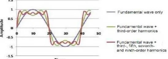
The output of NCO module will be a square wave at the configured frequency. A square wave has many frequency components with the main frequency being the center frequency, as per the NCO configuration. A square wave could be generated by adding a series of pure tones (sine waves) with appropriate amplitude and phase as per the Fourier Transforms. Fourier theorem assumes that the user add sine waves of infinite duration.
ISSN(Online): 2320-9801
ISSN (Print): 2320-9798
I
nternational
J
ournal of
I
nnovative
R
esearch in
C
omputer
and
C
ommunication
E
ngineering
(An ISO 3297: 2007 Certified Organization)
Vol. 4, Issue 4, April 2016
Therefore, a square wave is essentially composed of Fundamental frequency -1/3 of third harmonic tone +1/5 of fifth harmonic tone -1/7 of seventh harmonic tone, and so on.The square wave output from the NCO can be passed through a Band Pass Filter with a high Q factor to generate a sine wave at the desired frequency [2].
VII. CONCLUSION
In this paper the numerically controlled oscillator (NCO)with DDS method along with DAC have been discussed. As per study the speed of generation of sine wave can be increased by NCO.
This paper presents the frequency resolution and SNR can be improve in NCO than other conventional oscillators. The use of the NCO is not limited to the generation of a sine wave. By using a proper filter with an appropriate cutoff frequency, any desired wave shape can be rendered to the resultant output.
The key component of the NCO design flow is a fully parametrizable VHDL model. The look-up-table solutions in terms of switching speed, layout area and power budget.
REFERENCES
1. IreneuszJaniszewski, Bernhard Hoppe, and Hermann Meuth, “Numerically Controlled Oscillators with Hybrid Function Generators”, IEEE transactions on ultrasonics, ferroelectrics, and frequency control, vol. 49, no. 7, july
2. Priyankap. Chopda, Kavita S. Tated&Jayant J. Chopade, “Sine Wave Generation Using Numerically Controlled Oscillator Module”, BEST: International Journal of Management, Information Technology and Engineering (BEST: IJMITE) ISSN(P): 2348-0513;ISSN(E): 2454-471X Vol. 3, Issue 7 , 35-40, Jul 2015.
3. Hans-JorgPfleiderer, Stefan Lachowicz, “Numerically controlled oscillators using linear approximation”, 978-1-4244-3892-1 /09/$25.00 ©2009 IEEE
4. IreneuszJaniszewski,Bemhard Hoppe, and Hermann Meuth, FH Darmstadt, Darmstadt, Germany, “Precision and performance of numerically controlled oscillators with hybrid function generators”, 2001 lEEE International Frequency Control Symposium and FDA Exhibition, page no.744-752.
5. Gopal D. Ghiwala, Pinakin P. Thaker, GireejaD.Amin, “Realization of FPGA based numerically Controlled Oscillator”, IOSR Journal of VLSI and Signal Processing (IOSR-JVSP) ISSN: 2319 – 4200, ISBN No. : 2319 – 4197 Volume 1, Issue 5, PP 07-11, (Jan. - Feb 2013). 6. SnehalGaikwad, KunalDekate, “Design and Implementation of Feasible Direct Digital Synthesizer to Eliminate Manual Tweaking”, IOSR
Journal of VLSI and Signal Processing (IOSR-JVSP) Volume 2, Issue 4, , PP 53-56e-ISSN: 2319 – 4200, p-ISSN No. : 2319 – 4197, (May. – Jun. 2013).
7. Shachi P, R. Mishra, J. Ravi Kumar, “Counter Based Numerically Controlled Oscillator – A New Architecture” International Journal of Advanced Trends in Computer Science and Engineering, Vol.2 , No.1, Pages : 98-102 (2013) Special Issue of ICACSE 2013 - Held on 7-8 January, 2013.
8. Manoj Kollam, S.A.S.KrishnaChaithanya, Nagarajukommu, “Design and Implemation of An Enhanced Dds Based Digital Modulator for Multiple Modulation Schemes”, International Journal of Smart Sensors and Ad Hoc Networks (IJSSAN) Volume-1, Issue-1, 2011. 9. SiamakMortezapour,Edward K. F. Lee, “Design of Low-Power ROM-Less Direct Digital Frequency Synthesizer Using Nonlinear
Digital-to-Analog Converter”, IEEE JOURNAL OF SOLID-STATE CIRCUITS, VOL. 34, NO. 10, OCTOBER 1999.
10. SiamakMortezapour,Edward K. F. Lee, “Design of Low-Power ROM-Less Direct Digital Frequency Synthesizer Using Nonlinear Digital-to-Analog Converter”, IEEE JOURNAL OF SOLID-STATE CIRCUITS, VOL. 34, NO. 10, OCTOBER 1999.
11. PetterKällström, “Direct Digital Frequency Synthesis in Field-Programmable Gate Arrays”, Institutionenförsystemteknik Department of Electrical Engineering, pp 6-13.
12. Eva Murphy, Colm Slattery, “All about Direct Digital Synthesis”, Analog Dialogue 38-08, August (2004), Available at:
http://www.analog.com/analogdialogue.