18th International Conference on Structural Mechanics in Reactor Technology (SMiRT 18) Beijing, China, August 7-12, 2005 SMiRT18-D02-6
SAMPLING OF REACTOR PRESSURE VESSEL INNER CLADDING
FOR RETROSPECTIVE DOSIMETRY ANALYSIS
Miloslav Rucha
ř
Senior design engineer,
ŠKODA JS a.s.,Orlík 266,316 00 Plze
ň
,
Czech republic
Phone: +420378042960, Fax:
+420378042674
E-mail: miloslav.ruchar@skoda-js.cz
Josef Hógel
Senior research scientist,
ŠKODA JS a.s.,Orlík 266,316 00 Plze
ň
,
Czech republic
Phone: +420 378 042 438,
Fax: +420 378 042 749
E-mail: josef.hogel@skoda-js.cz
ABSTRACT
This paper describes a project the main goal of which was to take off material from the VVER reactor pressure vessel (RPV) inner cladding in order to evaluate neutron fluence for the entire period of nuclear power plant unit operation. Comparison of induced activities of 58Co and 54Mn in taken samples with the values of activities measured in fluence monitors located at the external RPV wall and in surveillance specimens capsules allows us to verify the used attenuation factor over the RPV wall and lead factor of surveillance specimens irradiation. From 93mNb activity measured on taken samples it is then possible to determine the neutron fluence for the entire period of the reactor operation and to assess the total radiation load and to determine the residual RPV lifetime. The following text deals with the project solution from the determination of sampling places and number of samplings through the selection of sampling technology and capture of samples, design of sampling equipment and evaluation of the action made in RPV.
Keywords: reactor pressure vessel (RPV), retrospective dosimetry, nuclear power plant Dukovany (EDU), nuclear power plant Temelin (ETE), reactor core, primary circuit (I.O.)
1 INTRODUCTION
The knowledge of fast neutron flux density, spectrum, and fluence impinging the inner RPV wall is one of the basic criteria for the supervision of its safety operation and the evaluation of its residual life time. Due attention is paid to the determination of the above mentioned quantities at NPPs operated in the Czech republic. All units are equipped by innovated surveillance programs and the neutron fluence monitoring at the RPV outer wall is compulsory for each unit and cycle [1] [2]. The experimental determination of the fast neutron fluence at the RPV inner wall is, however, complicated by the fact that the monitoring cannot be carried out directly on the inner RPV wall.
The first monitoring at the Dukovany Nuclear Power Plant (EDU) was performed during the first two campaigns of Unit 2. With a time interval, continual monitoring of all four Units was started in 1992. The monitoring at the Temelin Nuclear Power Plant (ETE) has been performed since the start-up of both Units, and in addition, activation measurements were carried out here using a larger set of activation detectors within the power start-up.
As already mentioned, the coefficients obtained during the model experiments, which were never confirmed by direct measurements at real RPV, are used for the re-calculation of obtained values to the RPV inner wall and 1/4 of its thickness. Some experts often doubt the application of them. A matter-of-fact objection against the usage is a doubt to what degree the model is representative for the power plant itself. The main differences are as follows:
• model dimensions,
• usage of fresh, non-burntout fuel and related differences in fission spectra,
• impossibility to simulate the decrease of water density in the core under operational conditions.
The determination of the above mentioned conversion factors by purely computational methods is currently burdened with uncertainty of up to 30%. And from the user’s standpoint is this value unacceptable. One, and currently perhaps the only one, possibility how to obtain direct experimental results about neutron flux density and fluence on the internal RPV wall is to take samples from the inner RPV cladding. For this method which has been already applied at some of operated („biopsy“) and shut-down („autopsy“) nuclear power plants, the name of Retrospective Dosimetry has been established. The designation is derived from the fact that for the determination of fast neutron fluence is used the measurement of 93mNb activity from threshold reaction of type (n,n’) on niobium. The long half-life of this radionuclide (16,14 years) allows to determine the fluence for the entire time of operation. This method is currently paid big attention to worldwide, whereas the interest is not limited only to the application at nuclear power plants of type VVER. Likewise, its utilization is not limited only to the pressure vessels, it can also be used for the determination of reactor internals radiation load. The main problem is the issue of sampling and the measurement of niobium specific activity whose content in steels ranges from several ppm to one per cent. Current methods for the determination of niobium weight in taken samples and its activities already allow to obtain experimental results, the uncertainty of which is comparable with activation measurements performed in the reactor cavity and in surveillance specimen capsules.
2 SAMPLING PLACES
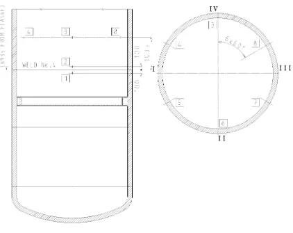
With respect to correct determination of vessel radiation damage the choice of sampling places is relatively unambiguous. The sampling shall be carried out in places where azimuthal fluence maxima are achieved, i.e. first of all at the core mid-level and then in the place of weld in the bottom part of the core. But as the sampling directly in the weld position is undesirable, there was decided to perform it 100mm above and below the weld.
With respect to azimuth-sampling, it is recommended to carry out the sampling in all six maxima as in this way we can eliminate any doubt concerning the complexity of obtained results. Different fluences in individual maxima can be caused by geometric factors (core basket and RPV alignment, RPV diameter deviations – in case of EDU reactors, both is negligible) and asymmetries in fuel loading (measurements of individual assemblies´ output is not carried out for each assembly, the computational values just more or less presume the core symmetry).
Fig. 1 Sampling places on EDU RPV
In order to precisely determine the specific activity of niobium, individual laboratories usually requires samples of weight 100 mg. Reliance upon a single measurement would represent an immoderate risk, in addition to that, at least one sample shall be archived for an eventual later analysis, i.e. the minimum amount of sampling was chosen in the range of 300 - 500 mg.
3 SAMPLING REQUIREMENTS
Resolution of the sampling method represents a key problem when solving the whole issue. While the evaluation of taken samples is solved on a laboratory-research basis, the sampling itself is a single matter and represents a sensitive irreversible intervention in the operated equipment. The care when selecting a proper form of sampling shall be in correspondence with that.
The sampling method itself offers several alternatives, such as drilling, milling or grinding off. The following requirements must be respected during sampling:
• maximum sampling depth and shape shall not represent any risk to the pressure vessel integrity,
• sampling shape and depth shall not constrain the performance of periodic in-service inspections, namely ultrasonic tests performed by automated technique using a manipulator SKIN from the internal pressure vessel surface,
• rise of any possible future discontinuity nucleus shall be avoided,
• samples taken from individual places shall be separated,
• samplings shall be registered in the discontinuity data base.
4 SAMPLING EQUIPMENT
In order to realize the sampling, it was necessary to design new equipment (OVZ Module) satisfying the above requirements. The design considered the use of the existing manipulator SKIN that our firm uses for in-service inspections of operated RPV. This solution has simplified the design of OVZ Module as it allowed to use manipulator drives for the OVZ Module positioning in the altitude, azimuthal and radial positions against the RPV wall including the possibility of radial thrust on the wall with a force up to 250 N. The existing camera and lighting systems of the manipulator could then be used for the monitoring of situation.
4.1 Sampling technology and design of a tool
The technology selected for sampling consisted in milling a vertical shallow groove whose maximum design depth was limited to 1mm. From a number of samples required from each sampling place, a tool shape in the form of a frontal two-edge milling cutter has been designed. The tool prototype was subject to a series of tests in SJS with the aim to find optimal cutting conditions affecting the shape of taken samples, a shape and quality of the groove in RPV as well as the cutting life of the tool. All these tests were performed on one of the RPV surveillance segments so that the cutting conditions during actual sampling were simulated to maximum extent. The resulting sampling tool shape is evident from Fig. 2.
Fig. 2 Shaped two-edge frontal milling cutters
A graph of milling depth dependence on the amount of taken metal was developed for the final tool shape – as shown in Fig. 3.
0 1 2 3 4 5 6 7
0 0,2 0,4 0,6 0,8 1 1,2 groove depth [mm]
groove width [mm] sample weight [g]
Fig. 3 Graph of sampling geometry dependence on the amount of obtained samples
4.2 Design of sample capture
As already mentioned before, the project considered eight samplings as maximum from eight different places per one setting of the OVZ Module in the RPV. For this reason the module has been designed with a receiver capable to contain eight intercepting filters with filter-beds. The permeability of filter-beds has been designed with respect to the shape of taken samples and to achieving a low pressure loss of the filter.
The filter prototype (see Fig. 4) together with the module pump (see Fig. 5) were tested in SJS in order to verify their parameters.
Fig. 4 Filter prototype with samples
Fig. 5 Pump and shaped milling cutter clamped in a spindle
4.3 Design of equipment
The final structure of OVZ Module was designed for the chosen sampling technology and capture method (see Fig. 6). This equipment utilizes the above described possibilities of the manipulator SKIN and completes them by functions needed to perform the sampling itself. These include a rotary drive of the sampling tool, vertical tool feed, pumping and capture of taken samples in filters and replacement of a filter after sampling from each place.
A holder, which serves for mounting the OVZ Module onto the manipulator SKIN and for inducing a thrust onto the RPV wall, is the base of OVZ Module. A sealed pressure bushing of the module which is connected to the distribution of pressure air of the manipulator SKIN is placed on linear guide ways of the holder. Inside the bushing there is a common drive of the milling cutter and the pump and also a linear drive with a stainless steel rod to assure vertical lift during sampling. In the front part of the module bushing there is a spindle with milling cutter and a pump radial impeller.
capable to contain 8 filters. Receiver rotation is derived from the vertical lift of the module and goes on after the completion of sampling and flushing of the pump route.
With respect to the RPV protection against damage during sampling the module linear drive is software-secured so that the feed should be immediately stopped when the tool speed drops below a preset value. This is to protect both the RPV and the tool. The design of common tool-pump drive then ensures that when the tool rotates and samples are taken, the samples are sucked into the filter and cannot be released in the I.O.
Module technical parameters are shown in Tab.1.
Tab.1 OVZ Module technical parameters
Tool revolutions 3100 rev/min
Tool feed 0,9 mm/s
Adjustable cutting depth 0,2 - 0,8 mm Adjustable groove length 0 - 80 mm
Flow through filter with bed cca 50 l/min at 3100 rev/min Filter-bed permeability 95-100 µm
Fig. 6 OVZ Module structure
5 EVALUATION OF SAMPLING
Two criteria were established for the evaluation of sampling, i.e. the intervention made to the RPV. The first one consisted in achieving the required amount of taken samples from each place where the minimum value was established to 300 mg. The other criterion consisted in compliance with max. design dimensions of all samplings as considered in the calculation report [4] assessing the interventions made to the RPV from the viewpoint of fatigue life.
Fig. 7 A sample taken from place No.5
Before sampling, specific activities of taken samples and exposure rate thereof were calculated by means of FISPACT program for the current state at the EDU, i.e. twenty campaigns of VVER440. By calculation considered weight of the sample was 1000 mg, the age of samples was considered for the irradiation termination date and then for 20, 100 and 300 days of holdup. Results show a sample exposure rate in the distance of 30 cm and as regards transport and handling with samples, the handling does not represent a serious problem.
Further sample management is not included in this contribution. Our main intention has been to familiarize with the issue of taking samples from RPV which are to be used for the determination of total radiation load of RPV using the Retrospective Dosimetry method.
6 CONCLUSION
Solution of the issue related to the accuracy of determination of neutron fluence on the inner RPV wall when using current experimental procedures has probably exhausted its potentials. Of course, it does not mean that the measurements are useless for the future, the results of monitoring of fluences on the outer RPV wall and in surveillance specimen capsules provide us with data which are absolutely necessary for the evaluation of RPV life time. The problem consists in re-calculation of these results to the inner RPV wall where no other actually credible improvement and more accuracy can be expected without direct measurements in this position.
The method of retrospective dosimetry has been developed for these measurements when no monitor can be placed in the vicinity of incriminated place. This method can be applied in larger extent, it can also be used for the determination of radiation load on another reactor internals such as core basket, reactor support cylinder, etc. The accuracy of determination of detection reactions activities (it relates namely to niobium) has already reached the level usual for activation measurements performed using clean materials, and that is sufficient for the purpose of fluence monitoring. Some laboratories are already capable to achieve this accuracy also for steels containing just tens ppm of niobium, whereas our case in more favorable in orders. The uncertainty of activity re-calculation to fluence is given mainly by the knowledge of neutron spectrum, in case of niobium with respect to its low reaction threshold it will vary around 10%. This value can be considered acceptable and it can also be expected that with the development of computational methods it will be reduced in the future and it will also be possible to perform new and more accurate evaluation of experimental results.
REFERENCES
[1] M. Brumovský, et al: Neutron Dosimetry for Reactor Pressure Vessels in Czech Republic, 10th Symposium on Reactor Dosimetry, Osaka, 1999
[2] J. Hógel: Ex-Vessel Fast Neutron Dosimetry for VVER Reactor Pressure Vessels in Czech Republic, 12th Symposium on Reactor Dosimetry, Gatlinburg, 2005
[3] M. Holman: Experimental research of spatially power distribution of neutrons in the inner shielding of light-water reactors, Thesis, VŠSE Plzeň, 1991