Techniques for Video Transport
at the ISDN Basic Rate
Tony L. Mitchell
Steven
L. Blake
Center for Communications
and
Signal Processing
Department of Electrical
and
Computer Engineering
North Carolina State University
TR-92j8
Techniques for Video Transport at the
ISDN Basic Rate
Tony L. Mitchell and Steven L. Blake
Center for Communications and Signal Processing Department of Electrical and Computer Engineering
North Carolina State University Raleigh, NC 27695-7914
June 19, 1992
Abstract
Substantial image data rate compression is necessary to support moderate resolution full motion color video transmission at the ISDN basic rate. Issues in digital image representation and error measures are introduced. An overview of differential, transform, subband, and vector quantization coding of images is presented, including comparisons and performance figures. In
addition, techniques for removing temporal redundancy, including conditional replenishment and motion compensated predictive coding, are discussed. Performance requirements and de-sign issues for video teleconferencing codecs are introduced. It is shown that compression on the order of" ' J 0.3 bit/pel is required for this application. Motion compensated predictive coding
techniques utilizing either adaptive DC'I' or vector quantization coding of the prediction errors have been proposed which can achieve the required compression levels. Due to hardware
1
Introduction
The objective of the Multi-Standard Video research project is to develop a video coding algorithm
that will allow "acceptable quality" full motion color video to be transmitted at the Integrated
Services Digital Network (ISDN) basic rate. This video capability is intended to form part of an
integrated communications architecture that will allow for the transmission of video, high resolution
still images, computer data, and voice over a basic rate (2B
+
D) link. This architecture will bedesigned for low cost implementation to facilitate ubiquitous access [1].
Due to the low capacity of the ISDN basic rate, high compression ratios are required to support
moderate resolution color video transport at a visually acceptable frame rate. Assuming that the
full2B channel capacity (128 kbps) is devoted to the voice/videolink, and that 16 kbps are allocated
to the voice signal (compressed voice), this results in a maximum capacity of112 kbps for the video
signal. At an image resolution of 200 X 200 pels (VCR quality) and a frame rate of 15 Hz (one
half of the NTSC frame rate), only 0.19 bits/pel can be allocated. Versus a 24bit/pel color source
image, this entails a compression ratio of f'V 125: 1.
This paper reviews the classic algorithms used in image (intraframe) coding. Techniques for
increasing the video compression ratio by taking advantage of temporal redundancy between frames
(interframe coding) are also examined. Then specific coding algorithms that have been proposed
for low bit rate video coding are discussed. A detailed analysis of the CCITT p X 64 kbps video
teleconferencing standard is included. It is shown that this standard provides a suitable framework
for implementing the desired multi-standard video architecture.
2
Fundamentals of Irnage Coding
2.1 Digital Image Representation
Transmission of video signals over digital telecommunications networks requires the transformation
of a continuous image field into the discrete domain. An analysis of image coding techniques should
be preceded by a discussion of the issues involved in the representation of discrete images.
As a consequence of Shannon's sampling theorem, it is known that a continuous image can
be preserved if it is sampled at its Nyquist rate. Since continuous images are essentially not
b andlimited, the chosen image sampling rate will define the resolution and hence the detail of
the reproduced image. Typical television images have a resolution of approximately 500
x
500(VCR's) deliver an image resolution of 200 X 300 pels. Bandlimiting must be performed by the
image capture device (video camera, scanner) prior to sampling to prevent aliasing.
The sample values obtained from the image capture device will lie in the continuous domain and
must be quantized for digital storage or transmission. The continuous image samples are usually
mapped into a finite set of discrete amplitudes which span the intensity range of the image. This
quantization process, where each quantized amplitude is represented by a unique digital code word,
is known as pulse code modulation (PCM). Monochrome images are usually uniformly quantized
at 8 bits/pel (256 levels). Ifless than 6 bits/pel (64 levels) are used for uniform quantization, then
contouring effects become visible in the reproduced image [2]. Non-uniform image quantization
characteristics, such as those that attempt to match the contrast sensitivity of the human visual
system (HVS) are also possible [2, 3].
Color images inherently require greater data capacity than their monochromatic equivalents.
Due to the trichromatic response of the HVS, (most of) the gamut of visible colors can be reproduced
by a linear combination of three orthogonal primary colors. This is the basis of operation for color
cathode ray tube (CRT) displays, where each color pel is represented by a red, green, and blue
phosphor dot. A common color space for image processing is the NTSC RNGNBN space. Each
pel is represented by a 3-vector representing the relative intensities of CRT phosphors required to
reproduce the color (or a subjectively close match). Typical "full color" images are represented
with 24 bits/pel (8 bits/pel for each red, green, and blue component). Although use of this color
space is intuitive, image processing need not be confined to a three primary space, but can also
be performed in a luminosity/chromaticity space, such as the NTSC YIQ space or the YUV
space. The color coordinates for these spaces can be found by a linear transformation of the
RNGNBN coordinates
[4].
The advantage of processingina luminosity/chromaticity space is thatthe chrominance frequency response of the HVS is shifted towards the lower spatial frequencies as
compared to the luminosity response [4,5]. Compression gains can be achieved by subsampling the
chrominance components of an image while still maintaining good subjective image quality.
Image coding is the application of image capture, pre-processing, compression, and possibly
post-processing techniques such that a continuous image field can be accurately and efficiently
represented in the digital domain. Compression algorithms are generally characterized as either
lossless or lossy. In lossless algorithms, the original quantized sample values can be exactly
recov-ered, assuming no bit errorsinstorage or transmission. The lossless algorithms generally are based
on entropy coding; more probable sample values (or blocks of sample values) are assigned shorter
code words so that the overall bit rate is reduced. Examples of lossless coding algorithms are the
Huffman algorithm, arithmetic coding, and ron-length coding [5]. Usually the lossless algorithms
are used. In the lossy algorithms distortion is introduced such that the original sample values
can no longer be exactly recovered (note that the quantization process also introduces distortion
which is inherent in any conversion from the continuous to the digital domain). The common lossy
image compression algorithms are predictive coding, transform coding, subband coding, and vector quantization.
When comparing the performance of various lossy compression algorithms, it is important
to have image fidelity measures which are both mathematically tractable and easily computable.
The most commonly used fidelity measure is the average least squares error (LSE), which is an
approximation of the mean square error (MSE) and is used when the statistics of the image ensemble
are not known [5]. The image signal-to-noise ratio (SNR) can be defined as the ratio of the image
power to the LSE power. An alternative measure (SNR') is defined as the ratio of the squared
maximum peak-to-peak value of the image to the LSE power. The value of SNR' is generally
12 to 15 dB larger than SNR [5]. The LSE measure is mathematically attractive since it can
be easily applied when optimizing compression algorithms; however, its performance does not
correlate well with subjective evaluations of image degradation. This is because the LSE averages
impairments over the entire image; large local distortions which are most visually objectionable do
not significantly effect the LSE. Other fidelity measures which try to incorporate HVS properties
are also possible, but they are generally harder to compute
[2].
Generally values of SNR' below 30dB indicate noticeable image degradation.
2.2 Predictive Coding
The number of bits/pel required to accurately represent an image (with low distortion) is a function
of the intensity range of the image and the variance of the pel values. An image with low pel variance
can be represented with few quantization levels while still maintaining low quantization distortion;
conversely, an image withhigh pel variance will require more quantization levels to maintain low
quantization distortion and consequently will require more bits/pel. The design of quantizers that
minimize mean squared distortion for a given sample probability density function (pdf) is discussed
in
[2, 5].
For lossy compression algorithms, the achievable compression ratio is a function of the tolerated
LSE. For an image which is an uncorrelated random field, the achievable compression ratio is solely
a function of the pel variance. In practice, images exhibit statistical pel correlation over various
regions. This correlation can be used to reduce the number of quantization levels needed to represent
a pel, increasing the compression ratio for a given distortion level.
of previous pel values, and the difference between the prediction and the actual pel value is quantized
and coded. Normally the predictor is a causal FIR filter and is designed based on an autoregressive
(AR) model of the image pel sequence. IT the AR model is accurate, then the predictor error
sequence willhave reduced variance as compared to the pel sequence, and fewer quantization levels
willbe required for the same distortion level. The pel predictor is usually preceded by the quantizer
in a feedback loop; the pel prediction is based on the quantized values of the previous pels [5]. In
this case the chosen AR model may not be optimum, but quantization errors cannot accumulate.
The coded pel values are reconstructed using a replica of the predictor loop. Note that if the
pel values fed to the DPCM encoder are already PCM quantized, then the error sequence can be
represented as a sequence of integers and can be coded without distortion using an entropy coder.
Linear DPCM predictors are often designed based on a stationary pth order AR model of
the image data. Experiments have shown that when the predictor coefficients match the picture
statistics, then filter orders greater than 3 do not yield substantial gains in MSE performance;
however, if the coefficients do not match, then MSE decreases are small for filter orders greater
than 1 [3]. 2D causal predictors can also be used; these tend to improve the subjective rendition
of vertical edges [3]. Typically a 2D pel predictor has non-zero coefficients for the three neighbor
pels to the upper left (assuming scanning progresses to the right and down)
[5].
Because imagestatistics are generally nonstationary, it is advantageous to vary the predictor model based on the
local image characteristics. This is often accomplished by measuring the directional correlationin
a region and switching to an appropriate predictor [3].
The pdf of the DPCM prediction error is usually modeled as a Laplacian distribution. The
optimal quantizer for such a pdfwill be non-uniform. Generally the quantizer is either chosen to
be a non-uniform Lloyd-Max quantizer, or a uniform quantizer followed by an entropy coder [3, 5].
An alternative means of designing the error quantizer is to minimize the mean square subjective
error based on some predefined visual fidelity criterion; experiments reveal that this technique can
yield gains of " J
1
bit/pel over a Lloyd-Max quantizer[2].
Varying the quantizer characteristicto account for the nonstationarity of the image statistics can lead to performance gains; this can
be accomplished by adapting to the the local quantization error variance or to some psychovisual
criterion [3].
For most images, 1D DPCM yields an 8-10 dB improvement in SNR over PCM at 1-3 bits/pel.
For 2D DPCM, the theoretical SNR improvement over PCM is approximately 20 dB, or about 3.25
bits/pel. Typically compression ratios of 3-3.5:1 can be achieved for 2D DPCM. IT the quantizer
is designed based on HVS properties, then compression ratios of 4-5:1 can be achieved at 30 dB
SNR' [2]. Entropy coding of a Lloyd-Max quantizer output yields about 1 bit/pel or 6 dB SNR
The primary advantage of DPCM as an image compression algorithm is that its simplicity
leads to an economical hardware implementation. The primary disadvantage of DPCM is that
the maximum. achievable compression ratio for low distortion reproduction is low. Also DPCM
decoders are sensitive to bit errors in the transmission channel, since the decoder forms an IIR
filter loop. Care must be taken to insure that the prediction filter is stable, so that the artifacts caused by bit errors decay rapidly [3].
2.3 Transform Coding
The goal of DPCM image coding is to map the image pels into a set of values that are uncorrelated
and that have reduced energy, so that coding gains can be achieved via reduced quantization
resolution. Because DPCM bases its predictions on causal one or two-dimensional filters, maximal.
pel decorrelation cannot be achieved since neighboring pels lying in the "future" can contribute
to prediction accuracy. One technique that can improve compression performance is transform
coding. Here, an image is segmented into multiple M X N blocks, and each block is transformed
into a new domain using a unitary (energy preserving) transform. The resulting M X N transform
coefficients should be uncorrelated and should exhibit considerable energy compaction into only a
few coefficients. The transform coefficients correspond to the weights of transform basis functions
needed to reproduce the original block. For correlated images, most energy is compacted into the
coefficients of the low frequency basis functions [5]. Compression is achieved by observing the
variance of transform coefficients over an ensemble of image blocks, determining the variance and
pdf of each coefficient, and designing quantizers for each coefficient that yield acceptable image
reproduction while reducing the number of bits needed to code the block. It has been observed
that for the various proposed image transforms, energy compaction improves for larger block size;
however the gains are usually small beyond block sizes of 16X 16 , and hardware implementation
is simplified for smaller blocks [3].
For an ensemble of image blocks with a known covariance matrix, the Karhunen-Loeve (KL)
transform exhibits optimal decorrelation and energy compaction performance over the ensemble
[3, 2]. The basis functions for the KL transform are the eigenvectors of the covariance matrix; the
transform coefficients are the corresponding eigenvalues. The minimum MSE representation that
can be achieved using only K basis functions is the set of basis functions corresponding to and
weighted by the K largest eigenvalues. The KL transform is not very useful for coding purposes
since the basis functions vary with the image statistics, and no general fast KL algorithm exists [2].
Alternative transforms that have deterministic basis functions are the Hadamard, the Haar,
transforms. All exhibit good energy compaction and have fast algorithms. The DCT, which belongs
to a family of sinusoidal transforms, is particularly suitable for image coding, with compaction
performance nearly identical to the KL transform for highly correlated first-order Markov sequences
(p
>
0.5)[2].
The DCT requires only real arithmetic and can be computed using an algorithmsimilar to the fast Fourier transform (FFT) (O(N2log2N) for N X N blocks). The DCT has been
chosen as the coding transform for the JPEG image coding standard [6], the MPEG video coding
standard [7], and theH.261 video teleconferencing standard [8]. Although other transforms, such as
the Hadamard, have much simpler computational requirements, their reduced energy compaction
performance as compared to the DCT prevents their use in high compression applications such as video transmission at the ISDN basic rate.
Compression is attained when using the DCT by reducing the precision used to represent the
transform. coefficients. The best visibly acceptable compression is achieved by maintaining high
precision (many quantization levels) for low frequency components, while reducing the number of
levels allocated to the higher frequency components that the HVS is less sensitive to. By observing
the transforms of ensembles of image blocks it is possible to determine the variance and pdf's of
the various transform coefficients. Usually the lowest frequency (DC) component is modeled with
a Rayleigh density, while the other coefficients are modeled as zero-mean Gaussian or Laplacian
densities [3, 5]. TheminimumMSE bit allocation within a block will allocate more bits to the lower
frequency coefficients. Compression can be achieved by applying zonal filtering, where only a subset
of coefficients with the highest ensemble variance are quantized, and the rest are thrown away [5].
The zonal filter mask can be static or it can be adaptive; image blocks can be classified as belonging
to different activity classes, each with its own zonal mask and quantization rule. One example of
possible activity classes are those which exhibit predominantly horizontal, vertical, diagonal, or no
structure [9].
An alternative to zonal filtering is threshold coding, where the coefficients of a block with
energy exceeding a given threshold are quantized, and the others are thrown away [5]. The decision
threshold can vary with the compression ratio, and should be set based on HVS visibility properties.
Threshold quantization offers improved performance over the use of a fixed zonal mask, since the
quantization rule can adapt to the varying block statistics. A disadvantage is that addressing
information of the quantized coefficients must also be coded; this can be accomplished by
run-length coding of the transition boundaries of the quantized coefficients [5]. Usually the coefficients
are scanned ina zig-zag pattern from the lowest frequency coefficient up. In addition to adaptively
selecting the coefficients to be coded, the quantization levels themselves can be varied according to
changes in the coefficients' variances
[2].
In either case, each block may be coded with a varyingnumber of bits; image quality at a fixed compression ratio is achieved by allocating more bits to
In general, the DCT yields higher compression ratios than DPCM for a given subjective image
quality. SNR' values greater than 30 dB have been achieved when adaptively DCT coding a
monochrome image at 0.5 bit/pel, yielding a compression ratio of 8-16:1 [5]. At high compression
ratios, block boundaries can become visible. This effect can be reduced by low pass filtering the
image [9], or by recursive block coding, where adjacent blocks overlap
[2].
Ineither case, for a fixedbit rate, image resolution is reduced. The DCT algorithm is much more difficult than the DPCM
algorithm to implement in hardware for real-time performance; however, recent advancements in VLSI processor performance allow the DCT to be utilized in real-time image coders [10, 11].
2.4 Subband Coding
Transform compression algorithms take advantage of the non-uniform spatial frequency sensitivity of the HVS by allocating more quantization levels to low frequency transform coefficients of the
image where quantization distortion is most perceptible. However, in the case of the DCT, the
spectra of the basis functions contain substantial energy over the normalized frequency range (0,1r)
(one-dimensional case) [12]. Better performance can be achievedifnarrow baseband and passband
filters are used to decompose the image, since greater control of the quantization noise spectrum. can be realized [13]. This is the approach taken by subband image decomposition techniques.
In subband image coding, the image being coded is fed into a filter bank consisting of two or
more two-dimensional filters. In a common example, the image is decomposed using four filters,
one of which is lowpass in both the horizontal and vertical directions, two of which are lowpassin
one direction and highpass in the other, and one of which is highpassinboth directions [14]. These
filters are designed to have narrow transition bands. Because the output of each filter has one-half the bandwidth of the image in each direction, each filter output can be decimated (subsampled)
by a factor of 2:1 in each direction (a reduction in sample points of 4:1 per filter output). The
decimated signals form four subimages; the total number of samples from the four filter outputs
equal the number of pels in the original image. If the filters are ideal, then the subimages can
be combined to reconstruct the original image after upsampling each subimage and interpolating
between null sample points using a reconstruction (synthesis) filter.
Non-idealities in subband filter implementation can lead to aliasing errors since filters with
non-zero transition bands are subsampled at their cutoff bandwidth frequencies. A realizable filter
function set which yields zero aliasing error is based on quadrature mirror filters (QMF) [14].
Near-exact image reconstruction can be achieved using a QMF decomposition if no quantization
distortion is introduced in the sub bands. 2-D QMF's are usually implemented as separable Fffi
response have mirror symmetry. It has been shown that filter design and aliasing errors are visually
insignificant in comparison to quantization error when 12 taps or more are used in the QMF
implementation
[15].
Increasing the number of taps results in a narrower transition band for eachfilter, but also resultsingreater computational requirements. Alternatives to QMF filters utilizing
fewer filter taps include symmetric short kernel filters [16]and IIR filters [17].
Various decomposition filter bank architectures have been proposed, incorporating 8, 11, and
16 subbands. Coding gains can be realized by applying different quantizer characteristics to each
subband. Fewer quantization levels are needed for satisfactory coding of edges, which are found in
the high frequency subbands [13]. The pdf of subband sample values is usually well modeled by
a Laplacian distribution [14, 13]. Substantial pel-to-pel correlation exists in the lowest frequency
subband, and therefore DPCM quantization is often applied here. Less correlation is observedinthe
higher frequency subbands; PCM quantization is usually applied in these bands. The Lloyd-Max
quantizer for each subband often does not produce the best subjective results since quantization
levels are clustered in the region of low sample amplitude, where distortion is least perceptible.
The quantizer characteristics are often modified to include a large dead zone [13, 16]. Entropy
coding of the coded sample values and run-length coding of the addresses of non-zero samples in
the high frequency subbands can further reduce the required bit rate. Various approaches have
been investigated to determine the optimal assignment of quantization levels to the subbands [18].
One technique is to use spatially varying quantizers that increase the quantizer resolution in areas
of a subband with high activity [14].
Subband image coding generally exhibits an increase in SNR of0.6-1.4 dB vs 8X 8 block DCT
coding at the same compression ratio [19]. At low bit/pel levels, subband coding produces a more
subjectively pleasing result than DCT coding due to the elimination of block boundary effects.
Because the subband filters are shift invariant, hardware implementation may be easier than DCT
coding. Since linear convolution of a filter with an image produces a larger resulting image, image
extension methods such as circular extension and symmetric extension are usually implemented so
that image truncation can be applied without introducing distortion in the reconstruction phase
[17].
2.5 Vector Quantization
DPCM, transform, and subband coding all achieve compression gains by taking advantage of the
correlated structure of images to reduce the number of bits required to represent an image with
sufficient fidelity. Each technique functions by transforming the pels of the original image into a
One consequence of Shannon's rate-distortion theory is that vectors of elements can be coded
more efficiently (with less distortion) than separately quantizing the scalar elements, even when
the scalars are uncorrelated or independent
[20].
Shannon's theory does not indicate how suchan optimal vector quantizer would be designed; over the past decade various vector quantization
techniques for image coding have been proposedin the literature
[21].
A typical vector quantizer for image coding functions by breaking the image into M X N pel
blocks, where each pel is PCM coded and can take on one of K possible values. The set ofall
possible image blocks has KMN elements; each possible block can be thought of as a vector in a
Euclidean space of dimension MN
[21].
Compression is achieved by determining a smaller set ofreproduction vectors and mapping each possible image block to the nearest reproduction vector(ina
distortion sense). A typical distortion measure is the LSE, which in a Euclidean space corresponds
to vector distance. The address of the selected reproduction vector is transmitted (or stored),
and the receiver reconstructs the compressed image by using the address to access a codebook of reconstruction vectors.
The most common technique for developing the reconstruction codebook is the LBG algorithm
developed by Linde, Buzo, and Gray
[22].
Given an initial training sequence of block vectors andan initial codebook, the algorithm iteratively replaces codebook vectors by the centroid of those
vectors mapped to each until the average distortion reaches a preset criterion
[20, 22].
It is hopedthat the training set chosen will be representative of the statistical distribution of image blocks
to be coded; the codebook chosen may not be optimal for the general class of images. Also, the
choice of the initial codebook may affect the final results; various methods for selecting the initial
codebook have been discussed in the literature
[20, 23].
Note that the LSE is usually chosen asthe distortion measure since it has an intuitive geometrical interpretation; however, an optimal
codebook in the LSE sense will not necessarily be subjectively optimal.
The number of bits/pel needed for coding in such a scheme is a function of the number of
pels per block (MN) and the number of reproduction vectors R in the code book; log2R bits are
required to represent each address, (log2R) / M N bits /pel are required for coding. As the block
size increases, the number of reproduction vectors required to adequately code the blocks will also
increase. Computational limits on determining the correct reproduction vector and storage limits
on the size of the code book tend to limit the size of blocks to 4 X 4 pels
[20].
A full search of thecodebook at the encoder can be avoidedifthe codebook is structured for a tree-search
[20].
The vector quantization scheme described above is known as spatial vector quantization (SVQ),
since the vector coded is an unprocessed set of pels in the spatial domain
[21].
Modifications of thisapproach have also been examined. Ifthe block of pels is normalized to unit energy and zero mean,
quantized. A similar approach is mean/residual vector quantization (M/RVQ), where the mean of
the block is scalar quantized, the quantized value of the mean is subtracted from the block and the
,
residual block is vector quantized
[21].
Since image statistics are usually not stationary, it may bedesirable to vary the vector code book based on some classification of the coded block (edge, texture,
etc.). This approach, known as classified vector quantization (CVQ), can improve the reproduced
fidelity of edges, which is normally reduced with standard vector quantization techniques
[24, 21].
Interblock correlation can be used to reduce the required coded bit rate by employing predictive or finite state vector quantizers, which vary the codebook for each block based on past block values
[25, 21].
Vector quantization can also be performed in a transform domain. Even though the coefficients of a transformed image block should be uncorrelated, coding gains can be achieved by vector
quantizing the coefficients rather than scalar quantizing them. The computational cost of designing
vector codebooks can be reducedifthe codebook is designedin the transform domain, since many
high frequency coefficients can be thrown away
[21].
An alternative is to code the low frequencycoefficients using scalar quantizers, and code the high frequency coefficients using a vector quantizer
[21]. Transform vector quantization (TVQ) can also be utilizedinCVQ systems; if the block being
coded is determined to belong to a "texture" class, it can be more efficiently coded by vector
quantizing a transform domain version of the block
[24].
When coding color images, whose pel values can be considered as vectors themselves, the vector
quantization problem encounters added dimensionality. When generating the vector codebook,
several alternatives exist. IT the image is represented in a particular color space (such as YUV),
then the color coordinate values for each pel can be thought of as a separate image or plane, and each
plane can be coded separately with identical or unique codebooks (color plane VQ). Alternatively,
each image block can be considered as having dimension3MN, and one codebook can be specified
for the image (combined VQ). This alternative will result in a much larger codebook which may
entail significantly higher computational resources to generate. Experiments show that combined
VQ yields slightly better distortion performance than plane VQ [26]. However, color plane VQ may be a more robust method in the general sense since it will likely be less sensitive to color variations
between the training set and images being coded [27].
Acceptable fidelity results can be obtained when vector quantizing images in the range of 0.3-0.5
bit/pel [20, 27]. One advantage of vector quantization coding is that the complexity ofthe decoder is
much lower than the complexity of the encoder, since the decoder essentially functions as a memory
lookup. However, in applications such as videotelephony, both an encoder and decoder must be present in every terminal device. Vector quantization coders are very sensitive to the statistics of
coding schemes such as SVQ or M/RVQ, the small block sizes that can be realistically handled may be too small to reduce interblock correlation.
3
Interframe Coding Techniques
3.1
Digital Video Characteristics
In the previous section, various techniques for efficiently coding digital images were examined.
When coding digital video signals, additional techniques can be introduced which can reduce the
required number of bits/pel needed to code the signal while maintaining good subjective quality.
A digital video sequence is formed by sampling a continuous image field in both the spatial and
temporal dimensions. The sequence consists of multiple distinct images, transmitted consecutively,
usually at a fixed rate. The distinct images are referred to as frames, and the number of frames
generated per second is the frame rate. The constraint on minimum frame rate is the subjective
capacity of the HVS to distinguish smooth motion from a jerky rendition; the frame rate of:film
motion pictures is 24 frames/sec, while the frame rate of NTSC television is 30 frames/sec. The
frame rate requirements should be distinguished from the display refresh requirements, which are
based on the critical fusion frequency (CFF) of the HVS; flashes of light above a frequency of
50-60 Hz are indistinguishable from a steady light source [5]. This is why NTSC television utilizes
interleaved scanning; the frame rate is 30 Hz while the field rate (the even or odd numbered lines) is
60 Hz. Interleaved scanning results in smoother motion rendition than frame repetition, at the cost
of reduced spatial resolution [2, 5]. High resolution computer monitors are usually progressively
scanned at a rate greater than 60 Hz.
As in digital image coding, pels in video sequences generally exhibit correlation with both their
spatial and temporal neighbors. In areas of a video image with little motion, particular pel values
will remain the same over the span of several frames. The temporal redundancy exhibited by video
sequences can be exploited to further reduce the average number of bits/pel needed to code the
sequence versus simply applying digital image coding techniques to each frame independently.
3.2
Interframe Predictive Coding
Coding gains for images can be achieved by taking advantage of the spatial correlation of image
pels; coding the difference between a pel and a prediction of its value formed from its neighbors
temporal prediction; in areas of slow relative motion, the difference between a current pel and its
temporal predecessor will have reduced energy and can thus be coded more efficiently. A frame
difference image (the difference between the current frame and the decoded reproduction of the
previous frame) can be coded using the same image coding techniques discussed in the previous section.
One technique for interframe predictive coding involves a spatial and temporal resolution
ex-change. This technique takes advantage of the property that the HVS has reduced spatial resolution
sensitivity in areas of large motion. A frame difference image is generated and is segmented into
a stationary region and a motion region (based on a threshold on the difference values). In the
stationary areas alternating pels are either repeated from the previous frame or are updated by the
frame difference signal (temporal subsampling). Inthe motion region pels are horizontally
subsam-pled by a factor of two (spatial subsampling) and the missing pels are interpolated. Addressing information for the location of the separate regions must be transmitted. Good subjective quality
can be achieved at rates of 2-2.5 bits/pel [5].
A similar technique is conditional replenishment. The frame difference image is again segmented into two clustered regions based on a threshold on the difference pel values. Small clusters are
discarded and addressing information is transmitted to indicate the cluster boundaries. Pels lying
in a stationary region are not updated from frame to frame, while pels lying in a moving region
are updated by the coded frame difference value for that pel. The number of bits per frame that are generated will depend on the amount of motion present in the sequence. Average SNR' values
of 34 dB (39 dB in stationary regions and 30 dB inmoving regions) can be achieved when coding
at an average rate of 1 bit/pel [2, 5].
3.3 Motion Compensated Predictive Coding
Prediction errors in interframe coding occur due to changes between successive image frames. These
changes can be due to scene shifts, but usually result from the motion of fixed objects within the
scene. Ifknowledge of the motion trajectories of each object could be determined and transmitted
to the decoder, then the prediction error could be reduced and significant coding gains could be
achieved. Motion compensation techniques attempt to improve the interframe prediction error
by estimating the motion of image pels between frames. Usually only translational motions are
determined.
One class of algorithms attempt to estimate the translational shift of each individual pel
be-tween frames by recursively optimizing the pel translation (motion) vector. These pel-recursive
descent procedure on the frame difference image [9, 5]. The advantages of these algorithms are that
pel motion can be tracked very accurately, and motion vectors need not be transmitted since the
decoder can perform the same recursive algorithm (though the algorithms can be sensitive to
quan-tization and transmission errors). The primary disadvantages of pel-recursive motion estimation
techniques are the extreme computational requirements [28].
An alternative to pel-recursive algorithms are block-matching algorithms. Here frames are
segmented into multiple M X N pel blocks. The translational motion between frames for each pel
in a block are assumed to be equal (rotational motions are neglected). The translation between
frames for each block is determined and transmitted as the block's motion vector. The decoder
constructs the next predicted frame by translating the blocks of the previously decoded frame along
their specified motion trajectories [9]. The prediction error can be coded and transmitted using
any of the previously described image coding techniques.
Various techniques for determining the motion vector for each block have been proposed. Each
generally involves propagating a new block within a search window from the previous frame that is
larger than the block size, and evaluating a prediction error function. The translation that yields
the minimum error is selected as the block's motion vector; generally block matching algorithms can
yield an estimation accuracy of 0.5 pel [9]. The proposed error measures are the cross-correlation
function (CCF), the mean squared error (MSE), and the mean of the absolute error (MAE) [28, 29].
Ingeneral the MAE measure is preferred, since it requires no multiplications or divisions and yields
comparable estimation performance [9].
The search window size is a function of the system frame rate and the estimated maximum
translation possible from frame to frame. Large search windows allow for larger possible motion
vector estimates but will generally require more computations to search. In an exhaustive search
procedure, every possible translation within the search window is evaluated; for a 2w X 2w window
and N X N blocks, (2w - N
+
1)2 evaluations must be performed [29]. Various techniques havebeen proposed to reduce this search effort, each based on the principal that estimate errors will
monotonically decrease as the translation vector converges to its optimal value. In[30] the authors
propose a 2-D logarithmic search procedure that functions by first evaluating the prediction error
function over a set of translation points distributed evenly throughout the search window. The
point that yields the lowest error lies in the direction of minimum distortion (DMD) and is chosen
as the center of a second search, with a narrowing of the possible search locations. This algorithm
proceeds until the search area consists of neighboring pel locations. Note that the evaluations at
each step of the algorithm. can be performed in parallel, but the steps must be executed sequentially.
Variations of this approach are discussed in [29, 28].
(such as YUV), the motion vectors are usually determined from the luminosity component only and
are applied when coding the chrominance components. The use of motion compensated interframe
prediction can lead to a bit rate reduction of 20-70 percent over conditional replenishment coding
[3].
3.4 Motion Compensated Frame Interpolation
A simple means of reducing the required transmission rate of video sequences is to reduce the frame
rate; however, this generally leads to a jerky image. Linear interpolation can be used to reconstruct
skipped frames, although this generally results in motion blurs whose visibility is proportional to
the speed of movement [9].
A more sophisticated interpolation technique would utilize motion compensation. Inthis
tech-nique block-matching interframe prediction is applied to a temporally subsampled set of frames
(1, 2, or 3 frames are skipped). The skipped frames are interpolated by projecting each block
fractionally along its trajectory [31]. Alternatively,ifmotion vectors for each block of the skipped
frame are available both from the preceding coded frame and the subsequent coded frame, then the
skipped frame can be constructed by an averaging of the projected blocks from both the backward
and forward direction [2]. This type of bi-directional prediction is usedin the MPEG video coding
standard [7].
Frame interpolation techniques suffer from the problem thatinmoving video sequences occluded
background material is often being uncovered. In addition, the block-matching prediction
algo-rithms do not handle rotational motion. Also, good displacement estimation accuracy is required
to preserve the rendition of moving edges [9]. These problems can be addressed by transmitting an
interpolated frame error image, although this will reduce the overall compression ratio. However,
motion compensated frame interpolation yields much better motion rendition that uncompensated
linear interpolation. In general, linear interpolation results in a MSE reduction factor of 2 over
zero-order interpolation (frame repetition), while motion compensated interpolation results in a
MSE reduction factor of 5 [32].
3.5 Three-Dimensional Transforrn/Subband Coding
An alternative means of reducing temporal redundancy in video image sequenc~sis to decompose
the sequence into various temporal frequency bands. Stationary regions in consecutive scenes will
exhibit energy primarily in the low frequency bands of such a temporal decomposition, while moving
be applied to each temporal frequency band to yield the desired motion rendition accuracy while achieving data rate reduction.
One means of achieving temporal frequency decomposition is to implement three-dimensional
transform. coding [5]. Video image sequences are divided into M X N X L cubes, where L is the
number of temporal (frame) samples included in the cube. A three-dimensional unitary transform,
such as the DCT, is applied to each cube. In stationary regions, most to the energy will exist
in the temporally lowpass coefficients. The performance of three-dimensional transform coding is
generally inferior to motion compensated interframe predictive coding
[5].
This is due to the factthat the DCT basis functions do not form an accurate model of the linear translational motion that
frequently occursin video sequences.
Another proposed technique is three-dimensional subband decomposition [33, 34]. In this
tech-nique, an image sequence is first passed through a temporal filter bank and separated into temporal
frequency bands using narrow bandpass and passband filters. The resulting subimages can be
tem-porally subsampled at their new Nyquist rate, conserving the number of original sample points.
The temporal subimages are then applied to spatial filter banks. Reconstruction proceeds as in
spatial subband synthesis, with the addition of temporal reconstruction filters. It has been observed
that most energy exists in the subbands that are lowpass in all dimensions (temporal, horizontal,
and vertical) [33, 35]. Different quantizer characteristics are applied to each subband based on their
observed pdf's. This technique is particularly suitable for packet video transmission.
4
Issues in Video Teleconferencing Codec Design
4.1 Performance Requirements
Due to the expense of digital transmission facilities and to the high information rates that
charac-terize digital video, it is desirable to efficiently code (compress) video signals prior to transmission.
The amount of compression that will be required will be a function of the transmissionlink
capac-ity, the resolution requirements, and the motion rendition requirements of the video service. Note
that as higher compression ratios are required, the implementation complexity, and consequently
the cost, of the video codec (cadec-decoder) increases. Note also that as the compression ratio
increases degradations are introduced into the reproduced image that can have an impact on the
resulting service quality. The design of digital video systems ultimately reduces to an economic
tradeoff, where the cost of transmission capacity is weighed against the cost of video codec
hard-ware. For a given transmission bit rate, certain service quality requirements may be impossible to
transmission channel capacity.
Historically, digital transmission systems based on copper wire carrier have had capacity
con-straints imposed by the bandwidth limits of the wire channel. Consequently, the cost of transmission
capacity over these facilities has not decreased at a rapid pace. The introduction of basic and
pri-mary rate ISDN services, as well as fiber optic based broadband ISDN services, may lead to a
dramatic reduction in transmission capacity costs. However, due to the installation and
mainte-nance costs for these facilities, the cost of transmission capacity can not be expected to decrease
as rapidly as the cost of digital signal processing hardware needed for video codec implementation,
which rides the dramatic cost reduction curve of VLSI logic devices that has been observed over
the last decade and which should continue throughout the next. The overall economic argument
favors conserving transmission capacity requirements by aggressively applying video compression techniques.
Entertainment video services (such as broadcast television) have stringent requirements on
motion rendition and SNR. The necessity for smooth motion reproduction means that a frame rate
of 30 frames/sec (or higher) must be supported. The possibility of large motion shifts means that an
accurate motion displacement estimation algorithm must be usedifmotion compensated prediction
is incorporated into the coding algorithm. Also, the motion and resolution requirementswillplace
a constraint on the maximum compression ratio that can be utilized, since at high compression
ratios edge rendition for stationary and moving images is usually impaired. Assuming a luminance
resolution of 500X500 pels and a chrominance resolution of 250X250 pels per frame, the video image
will consist of 375,000 sample values per frame (250,000 pels/frame for the luminance component
and 62,500 pels/frame for each chrominance component). Assuming a frame rate of 30 frames/sec,
7,500,000 pels/sec will be generated. This figure gives an indication of the compression ratio (in
bits/pel) that will be necessary for a given transmission channel capacity. Coding this signal for
transport over a 1.544 MbitZsecT1 channelwill require a coding rate of 0.206 bits/pel (0.137 bits
per luminance or chrominance sample value). This application probably cannot be supported at
that bit rate, since the extremely high compression ratio required (rv 60:1)will likely degrade the
reproduced image beyond desired image quality constraints.
Video teleconferencing services do not impose the same performance requirements as
enter-tainment video. Usually the scenes being transmitted consist of head and shoulder images with
restricted motion. High resolution and accurate motion reproduction are usually not required. Some
degradationin the image quality is acceptable. The overall objective of the service is to enhance
in-terpersonal communication by creating the illusion of closeness between conference participants who
may be separated by thousands of miles. Because of the relaxed performance constraints, higher
When coding a color video sequence with an image resolution of 200X200 pels, there are 40,000
pels per frame. When coded at 0.5 bits/pel, 20,000 bits per frame must be transmitted. At a frame
rate of 30 frames/sec, a channel capacity of 600 kbits/sec is required, while when coding at a frame
rate of 10 frames/sec, 200 kbits/sec are required. Neither of these bit rates can be supported over
an ISDN basic rate channel, which provides two 64 kbits/seccircuit switched B channels and one 16
kbits/sec packet switched D channel. Increasing the compression ratio by coding at 0.2 bits/pel will
result in 8,000 bits per frame;iftransmitted at a frame rate of 10 frames/sec, 80 kbita/sec capacity
is required, while when transmitted at 15 frames/sec, 120 kbita/sec capacity is required. Both
of these rates can be supported over two B channels on an ISDN basic rate interface (although
at the 120 kbits/sec video rate little residual channel capacity will be available for coding the
accompanying voice signal). Note that as the frame rate is decreased, the performance of motion
compensated interframe prediction algorithms will be reduced, and consequently the subjective
image quality at a fixed bit /pel value will vary with the frame rate. It is clear that when providing
a video teleconferencing service over an ISDN basic rate interface, even when supporting moderate
resolution video at a reduced frame rate, extensive video compression will be required.
4.2 Channel Access
Video codec hardware must be interfaced to the digital transmission channel used. Most digital
transmission systems in use today are constant bit rate (CBR) channels. Examples include the
ISDN basic rate, the ISDN primary rate, Tl carrier, and DS-3 carrier. When accessing a subset of
each channel's capacity, time division multiple access (TDMA) is usually used as the multiplexing
scheme. These channels generally provide a circuit switched service; fixed capacity and constant
delay are provided to the video source over the life of the connection. Packet switched video services
are also possible, but the characteristics of these systems, such as variable bit rate (VBR), variable
delay, and the possibility of blocking, pose potential performance problems for video services.
CU1Tent standard proposals for the BISDN specify an asynchronous transfer mode (ATM) packet
switching protocol, allowing variable bit rate services. Issues encountered when supporting video
services on the BISDN network are discussed in [36].
Access buffers are usually incorporated into the video codec and network interface hardware
to isolate the timing of the codec from the network clock. If the video coding algorithm does not
generate bits at a constant rate, then the access buffer must be used to absorb the bit rate variations
of the codec before transmission over the channel [3]. Any coding algorithm that incorporates
entropy coding to generate variable length codewords (VLC's) for image data values will have a
variable bit rate. VLC's are often used to efficiently code motion vectors and quantized pel or
based on their energies or on perceptual criteria will generate data at a variable bit rate. Since the
goal of any efficient video coding scheme is to code the image data at its entropy rate, and since
the information content of video sequences varies as a function of the motion content, these coding
algorithms will inherently generate bits at a variable rate.
The delay and synchronization requirements of video services result from the short frame refresh
period (33 msec for a 30 frame/sec frame rate). This imposes a limit on the maximum allowable size
for a transmission access buffer, since the total number of bits used to code a frame must be able
to pass through the buffer within the frame refresh period. Because the buffer must be of finite
capacity, and because the video coding algorithm will probably be of variable bit rate, overflow
is possible. This problem can be addressed by frame skipping; i.e.: by repeating a frame at the
receiver and by clearing the buffer to free capacity for the next coded frame
[2].
However, frameskipping will generally lead to undesirable motion artifacts. It is usually necessary to control the
rate of data generation by the codec to prevent buffer overflow. This is often accomplished by using
buffer occupancy feedback to adapt the compression ratio of the coding algorithm. For DPCM and
transform coding algorithms, quantizer step sizes are often increased as the buffer fills so that fewer
reconstruction levels are allowed and fewer bits need be transmitted. Perceptually-based masking
thresholds can be increased, reducing the number of quantized sample or coefficient values. More
sophisticated algorithms perform a spatial/temporal resolution exchange, taking advantage of the
insensitivity of the HVS to spatial resolutionin areas of large motion
[2].
Each of these procedures,ifnot carefully designed, will lead to time-varying perceptual image quality, such as time-varying
noise levels or motion blur. These artifacts will be objectionable to the viewer. However, an
adaptive coding algorithm should provide better perceptual results than an algorithm operating at
a fixed bit rate.
Bit errorsin the transmission channel will be encountered at some rate. For DPCM intraframe
coding, bit errors usually result in the addition of a noise smear propagating in the direction of pel
scanning. Transform coding generally provides better error masking performance, since a coefficient
error is distributed as noise across a block, and does not propagate throughout the image [5]. Errors
in VLC's can severely degrade the performance of entropy decoders. Errors in motion vectors or
in synchronization signals can drastically impair the video service quality. For these reasons it is
imperative that the bit stream received by the decoder have an extremely low probability of bit
error. Retransmission of erroneous video data is generally infeasible, since packetization protocols
are usually not used and because the tight delay constraints of video transmission do not allow
for an extra round-trip propagation delay between receivers located at any appreciable distance
apart. The bit error rate observed at the decoder can be driven arbitrarily low by the application
of error corrective coding (ECC); i.e.: by the introduction of redundant data bits into the channel.
technique is block coding, where N data bits are transformed into a larger set N
+
K of ECC bits which are transmitted. ECC is commonly implemented in consumer compact disk players usingVLSI ASIC's. Example block coding techniques are Bose-Chadhuri-Hocquenghem (BCH) codes and Reed-Solomon codes [37].
4.3 Coding Algorithm Selection
It was shown earlier that when coding moderate resolution color video signals for transport over the
ISDN basic rate, coding rates of
rv
0.2 - 0.3 bits/pel are required. Note that the compressionper-formance results for the intraframe techniques discussed in Section 2 were for monochrome images
only; additional bandwidth
(rv
50%) is required for the two subsampled chrominance components.The classic intraframe coding techniques do not in themselves provide acceptable performance at
these large compression ratios (40-60:1).
Ina similar vein, interframe coding techniques such as conditional replenishment do not provide
sufficient compression for ISDN basic rate video transport. It appears that only through the
application of both efficient motion compensated prediction and efficient residual error coding can
sufficient video compression be achieved to support ISDN basic rate transport at an acceptable
frame rate and with acceptable subjective quality. The two most common techniques proposed for
such a codec architecture utilize either adaptive DCT coding or vector quantization to code the
interframe prediction error. Proposals utilizing subband coding for low bit rate video applications
are not prevalent inthe literature.
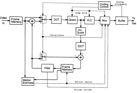
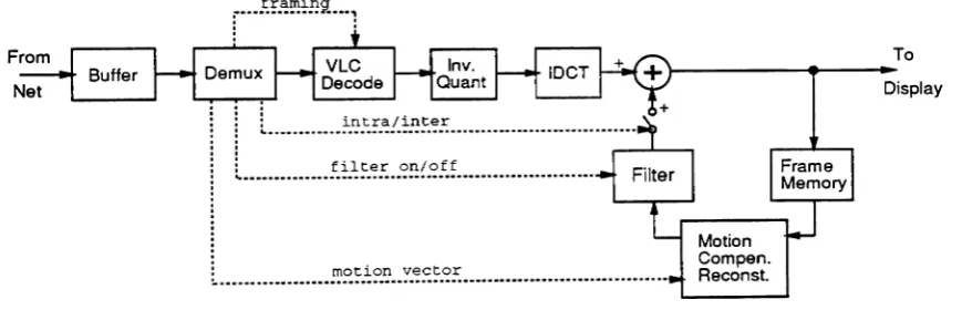
Codec architectures utilizing motion compensated prediction with adaptive DCT coding of
the residual prediction error are discussed in [38, 39, 40, 31, 8]. In these algorithms, adaptation
of the coded DCT coefficients is incorporated to respond to varying prediction error statistics.
The quantization resolution is varied as a function of access buffer occupancy to prevent buffer
overflow. This results in a simple form of spatial/temporal resolution exchange; in scenes where
motion is low and motion compensated prediction is accurate, the error blocks are coded with finer
detail, leading to improved spatial resolution. Common degradations observed with these adaptive
algorithms are spatially varying block SNR, visible block edges, and mosquito noise (a fluctuation
ofluminance/chrominance levels on moving edges) [38]. These degradations are usually addressed
by various pre- and post-processing procedures, such as filtering [31]. Entropy coding, specifically
run-length and Huffman coding of transform coefficients, and differential and Huffman coding of
motion vectors, are usually incorporated to further reduce the required bit rate.
Motion compensated adaptive nCT coding is computationally complex, and requires substantial
[10, 41]. The motion vector search algorithm, which must be performed only in the encoder (but
which will exist in the majority of video teleconferencing terminals), requires several hundred million
operations per second (MOPS) [42, 43]. Within the last year single-chip VLSI processors capable
of performing the required motion compensated prediction have been announced [11, 43, 44].
Predictive vector quantization (PVQ) has also been proposed as a means of coding video
se-quences at low bit rate [21, 45]. These algorithms usually use the index of spatial and temporal
neighbor vectors to predict the index of the vector being coded. Motion compensated prediction
can also be incorporated. Due to the non-stationarity of image statistics, a single uniform vector
codebook is generally insufficient for video sequence coding. The PVQ video coding algorithms
usu-ally incorporate a means of updating the codebook at the encoder and decoder to track the varying
image characteristics from frame to frame. Vector quantization can also be used to code DCT
transform. coefficients of motion compensated prediction errors [21]. Although vector quantization
coders can deliver good subjective image quality, the tremendous computational requirements of
the encoder have prevented low-cost VLSI implementations from appearing.
5
CCITT H Series Recomrnendations for Video Transmission
5.1 Introduction
With the anticipated introduction of ISDN services internationally, it will soon be possible to
pro-vide advanced communications applications, such as pro-videotelephony and multimedia data, to a
broad segment of the business and residential customer base. Because of the tremendous demand
for video communications services, and because of the need for compatible hardware and
proto-cols to provide these services, the International Telegraph and Telephone Consultative Committee
(CCITT) has recently completed development of the Hseries of recommendations for audio-visual
communications. This set of recommendations is often referred to as the CCITTp X64 kbps video
coding standard, since the recommendations are structured for use over ISDN B channels. The
integerp can vary from 1 to 30 (from one B channel at 64 kbps to an H12 channel at 1920 kbps).
The CCITT p X 64 kbps standard is composed of five recommendations (at present):
• Recommendation H.221 - Frame structure for a 64 to 1920 kbit/s channel in audio-visual
teleservices
• Recommendation H.230 - Frame-synchronous control and indication signals for audio-visual
• Recommendation H.242 - System for establishing communication between audio-visual ter-minals using digital channels up to 2 Mbit/s
• Recommendation H.320 - Narrow-band visual telephone systems and terminal equipment
• Recommendation H.261 - Video codec for audio-visual services at p X 64 kbit/s.
These recommendations specify the video coding algorithm, the possible speech and audio coding
algorithms that can be utilized (from other CCITT standards), the frame structure for integrat-ing these bit streams with optional data channels, and the control and connection procedures for
establishing and maintaining an audio-visual communications service using from 1 to 30 ISDN B channels. They should allow for the development of compatible videotelephony and video
telecon-ferencing terminals, while allowing the integration of vendor-proprietary services such as still image transfer and data transmission applications.
5.2 Recommendation H.221
The CCITT designed the frame structure of the p X64 kbps video coding standard to incorporate
in-band signaling, since the standard can also be implemented over existing digital transmission facilities that do not provide out-of-band signaling (such as an ISDN D channel). Connections
for audio-visual services are initially established over one 64 kbps channel (referred to herein as a
B channel), called the initial channel[46]. This channel has a capacity of 8000 octets/sec; each
successive bit modulo 8 is defined as a subchannel, labeled SCI through SC8; SC8 is defined as
the service channel. Each block of 8 bits spanning SCI - SC8 is an octet. A block of 80 octets is
defined as a frame. Frames repeat with a period of 10 ms. A sub-multiframe (SMF) is defined as
two consecutive frames; a multiframe (MF) consists of sixteen consecutive frames.
A frame alignment signal (FAS) is carried in octets 1-8 of the service channel for each frame.
This 8 bit signal allows the receiving terminal to achieve frame synchronization. The value of
the FAS varies between even and odd numbered frames, but the general structure repeats every
SMF. The FAS incorporates a frame alignment word, multiframe numbering, channel numbering, a
multiframe alignment indication bit, and an optional 4 bit cyclic redundancy check (CRC) (applied
to all channels utilized in the audio-visual session).
A bit-rate allocation signal(BAS) is carried in octets 9-16 of the service channel for each frame. This 8 bit signal is used to carry codewords specifying the allocation of bandwidth to various
components of the audio-visual service, such as the audio bandwidth, the video bandwidth, and any
allocation of the component signals during the audio-visual session. The receiving terminal state can be changed by a BAS codewordina period of two frames, or 20 msec.
Anoptionalencryption control signal(ECS) can be carried in octets 17-24of the service channel for each frame. This signal, ifutilized, absorbs 800 bps of channel bandwidth. The remainder of the service channel (octets 25-80) can be allocated to other component services. IT the ECS signal is utilized, then 61.6 kbps of capacity is available on the initial channel; ifthe ECS is not utilized, then the FAS and BAS signals occupy1.6kbps of bandwidth, leaving62.4kbps of available capacity on the initial channel.
IT multiple B channels are utilized for the audio-visual service, then the additional channels are usually framed using the same structure as that in the initial channel (without the optional
EeS).
The FAS and BAS signals in the initial channel are used to control all of the B channels in the session. The FAS and BAS signals in the additional channels are only used for channel numbering and synchronization. It is important that all channels in the session maintain multiframe alignment; the receiving terminal may delay the signals arriving from the additional channels to achieve multiframe alignment. IT switching service at rates higher than 64 kbps (such as at the HO (384 kbps), H11 (1536 kbps), and H12 (1920 kbps) rates) is provided, then the use of framing on the additional 64kbps channels is not mandatory. Unframed transmission is not addressed inthis report.A variety of speech and audio coding standards are specified for usein this recommendation. For framed transmission Recommendation G.7ll speech coding using the A-law or JL-Iaw rule at 56 kbps is specified. Higher quality audio coding (7 kHz bandwidth) according to Recommendation G.722 can be utilized at bit rates of 48 or 56 kbps. The speech coding mode is specified using a BAS command word. Command words are reserved for speech coding at lower bit rates, such as 40, 32,
24, and 16kbps, The algorithm for speech coding at 16kbps is being specified in Recommendation
H.200jAV.254; this recommendation should be completed by June 1992 [47]. This algorithm is
of special interest for audio-visual transmission at the ISDN basic rate, since it allows 108.8 kbps (2X62.4 - 16 kbps) of capacity to be dedicated to video transmission when utilizing only two B channels. Speech and audio rate decoding capabilities corresponding to these standards are also transmitted using BAS codewords. Usually the audio signal is transmitted in the initial channel.
Transfer rate commands and capabilities are specified using BAS codewords. The allowable rates include m B channels, with m varying from 1 to 6. In addition, n X 384 kbps HO channels can be allocated, with n varying from 1 to 5.
can be specified. The alternatives are H.261, the previous ISO audio-visual coding standard, or a
future improved coding algorithm. The video decoding capabilities of a terminal can be specified using BAS codewords. These include the acceptable video resolution; either QCIF or ClF (refer
to section 5.6). In addition, the acceptable frame rate, either 30, 15, 10, or 7.5 frames/sec, can be
specified.
Low speed data (LSD) rates for transmissionin the initial channel can be specified using BAS
command words. Rates of 0.3, 1.2, 4.8, and 6.4 kbps can be specified for transmissioninthe service
channel. Rates of 8 to 62.4 kbps can be specified for use inthe rest of the initial channel. The BAS
signal can be used to open and close these data channels as needed during the audio-visual session.
Low speed data rates using a multi-layer protocol (MLP) can be specified at 4 or 6.4 kbps, or at a
variable rate (depending on the remaining capacity in the initial channel). High speed data rates
(HSD) exceeding 64 kbps can be specified, with or without the use of a MLP. Receive data rate
capabilities can be exchanged using BAS codewords.
Application capabilities for the LSD /HSD channels can be specified using BAS codewords. These capabilities include ISO still picture transmission (baseline, spatial, progressive, or
arith-metic), graphics CurSOT, fax transmission (Group 3 or
4),
and terminal emulation (V.120). Thesecapabilities allow for the inclusion of multimedia data applications within the audio-visual service.
Further standardization of the use of these data channels is required [47].
5.3 Recommendation H.230
A variety of control and indication signals necessary for the operation of an audio-visual commu-nications session are specified in Recommendation H.230 [48]. Commands for video freeze picture,
video fast update, and loopback (audio and video) are specified in Recommendation H.221 using
predefined BAS codewords. Other H.230 signals are specified by a BAS escape value, followed by
an indication codewordinthe BAS codeword space of the following frame.
The H.230 signals not specified in Recommendation H.221 are divided into two categories; audio
indication and multipoint conferencing control and indication. The audio indication signals specify
whether the audio signal is active or muted. The multipoint conferencing signals are used for
controlling audio-visual sessions where a terminal can receive from more than one remote terminal
during a session, under the control of a multipoint control unit(MeU). Only a subset of the H.230
5.4 Recommendation H.242
Recommendation H.242 specifies the procedures implemented by terminals to establish and main-tain an audio-visual service [49]. Sessions are initiated by establishing an initial channel and activating framing (per Recommendation H.221). Terminals start the session by establishing a voice connection using A-law or p,-law coding (per Recommendation G.711) in the framed initial channel. Sessions are established in three phases; a capability exchange sequence, a mode switching sequence, and an (optional) frame reinstatement sequence.
As soon as the initial channel connection is established, either one of the terminals can initiate the capability exchange sequence by setting a timer and transmitting the terminal's capabilities, using BAS capability codewords. The initiating terminal examines the incoming data stream to determine whether or not the remote terminal has established multiframe alignment before the expiration of the timer. The initiating terminal must ensure that the complete capability set is transmitted to the remote terminal after that terminal has established multiframe alignment and prior to the expiration of the timer; else the capability exchange sequence is restarted. The remote terminal can begin its capability exchange at any time during this timer period.
Ifeither of the terminals wishes to operate the audio-visual session using additional channels, and it has determined from the capability set received from the remote terminal that this is possible, then it can begin to establish the additional connections (channels) using the connection procedures specific to the network. Upon establishment, the additional channels are framed and synchroniza-tion is attempted (per Recommendasynchroniza-tion H.221). In the mode switching sequence, BAS command words are exchanged between terminals to establish the desired services, such as a particular audio coding standard, a particular video transmission rate, a particular data transmission rate, etc. The desired mode of operation must be permitted by the remote terminal's capability set. The BAS mode command becomes effective at the remote terminal beginning with the first even numbered frame following the SMF where the BAS mode command was received. Asymmetric connections (different modes and/or bit rates for each terminal) are possible.
The mode of either terminal can be changed dynamically during the audio-visual communica-tions session by using BAS command words. Procedures are also defined for the addition/ dropping of channels, loss of synchronization, fault conditions, channel renumbering, and call transfer.
5.5 Recommendation H.320