SEISMIC R E S P O N S E A N A L Y S I S OF C O M P L E X S T E E L S T R U C T U R E S
George C. Lee, 0 Vladimir A. Rzhevsky, 2) Mai Tong 3) and Jin Wang 4)
1,2,3) Multidisciplinary Center for Earthquake Engineering Research, University at Buffalo 4) Structural Consulting Engineer (formerly from Dept of Civil Engineering, University at Buffalo) ABSTRACT
, The seismic behavior of a structure depends on the ground motion characters such as intensity, duration, and the dominant driving frequencies. It also depends on the dynamic properties of the structure such as strength, rigidity, and modal characteristics. In this paper, we analyze a complex building structure which can be viewed as a low-rise part and a high-rise part: the high-rise part consists of a 16 story tower, which is formed by three independent blocks; the low-rise part consists of 2-5 story structures, which are formed by 4 independent structural blocks.
The analysis is based on a Finite Element (FE) Model in which the load bearing wall system is modeled by steel flames. Double line of columns, sharing the common foundation, divides the building into seven blocks. Because the blocks are not connected at the floor levels, they are treated as independent structures in the analysis. The middle block of a 16-story structure connects to its adjacent sections by sliding joints. For this reason, when the building is subjected to high level of seismic loading (applied forces exceeding static friction on the sliding joints), pounding of the separate blocks may occur.
Fundamental periods of different building blocks vary from 1.1 to 4.7 sec. For time-history analysis the acceleration records of past strong earthquakes were used.
As was shown by the analysis, various building blocks may collide. To prevent this situation, some seismic protection and retrofit schemes were considered.
S T R U C T U R A L S Y S T E M
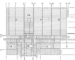
The structural system consists of low-rise and high-rise components' the high-rise part of 16 story tower (Block I), can be subdivided into three independent blocks; the low-rise part, 5 story (Block 2F-5K) can be subdivided on 4 independent blocks. The building has a plan size of 399x516 ft. (fig. 1). Height of the building varies from 2 to 16 floors. Maximal height is about 210 ft.
i 2 3 6 7 I0 II 14 15 16 17 18 19
I I
I
1¢
I
"IV
II
H
G'---
2 - F - ~ I ~ I - - - 4 - H ~ I ~ 5-K - ~
,d=:===:=:==~
I
jL , I
4 5 7 8 9 i0 12 13
Fig. 1. Plan Overview of Building Complex
SMiRT 16, Washington DC, August 2001 Paper # 1442
In Block I, according to the floor construction drawing, the load bearing wall system is modeled by steel frames. In Block 2F - 5K, load bearing wall system is modeled by steel trusses and partial steel beams.
The floor construction consists of a 3 1/2 " - 4 1/2 " poured light aggregate concrete on 1 1/2 " composite metal deck that is assumed to be rigid diaphragms in the FE Model.
Design model of the building was broken down as 7 independent structures: 4 blocks in the Western side (Blocks 2 F - 5K) and 3 blocks in the East side (l-A, 1-B and l-C). The middle block of a 16-storey building connects to its adjacent blocks by sliding joints (SJ). For this reason, when the building is subjected to high level of seismic loading (applied forces exceeding static frictions in the joints), pounding of the separated blocks may occur.
The FE Model is constructed by using SAP2000. The model consists of three main models: East (Tower) Block, model 1-ABC, West Block, model 2F-5K and model ALL. The summary data of the models are given in Table 1:
Table 1. S u m m a r y Data of the FE Model Finite Element M o d e l Data
Number of joint elements Number of frame elements
Number of stiffness degree of freedom Number of mass degree of freedom
1-ABC 1483 10678 18838 6634
2F 5K
3476 16045 32499 14464
ALL 4961 26732 51349 21101
In this paper we present the results of analysis of the East, 16 story part of the building, model I-ABC (fig. 2). This model consists of three main blocks: I-A, I-B and I-C, which are connected by sliding joints.
I-B
I-C
::~::: v,.h~,...,.~,,,.~,.. - .r-, ii.;~. ~ ,.5%._o_.I,:- F-.. ~, ~:Ir- 1 , F:: ~
> f ( ...
, °"hL::'
. . . o,
:!i:~?:~
Fig. 2. Model I-ABC
Fundamental periods of different building blocks vary from 2.6 to 4.7 seconds.
Time-history analyses were conducted by using SAP2000. Ground motions used in the analysis include E1 Centro, Northridge, Kobe, Turkey and Chi-Chi earthquakes.
The summary data of the models are shown in Table 2:
Table 2. Summary Data of the I-ABC Model
Data Number of joint elements Number of frame elements
1-A 559 3827
Finite Element Model 1-B
297 2789
1-C 566 4075
Number of stiffness degree of ~eedom 6615 4999 6957
Number of mass degree of freedom 2307 1748 2409
TIME H I S T O R Y ANALYSIS
Because the tower part of the building consists of three main structures with different dynamic properties, under seismic loads, there is a possibility when each of the building part moves separately, independent from each other. The minimum distance between the middle and the side wing blocks is about 1-2 feet. Taking into account that the height of the building exceeds 200 feet and the lateral resistance is weak, the possibility of pounding between these building components must be investigated. For structural behavior analysis under seismic loading, the response spectrum analysis and time history analysis were used. In this paper, we discuss the results of the time-history analysis.
The main purpose of this analysis is to determine the dynamic response and retrofit strategies for the structural and nonstructural components, so the information concerning the relative displacement between the different building blocks and the relative displacement between stories were taken from the structural analysis.
Because the joint lines between middle and side wing blocks of the building are the critical locations of possible structural, non-structural, pipelines and equipment damages, we gave special attention to the displacement of the few main joints of the building. Distance between joint 134150 (block A) and joint 139150 (block B) equal 1.125 ft. (Y axis). Distance between joint 134500 (block A) and 139500 (block B) equal 2.083 ft. (X axis) The same distances exist between blocks B and C.
Seven earthquake records were used in our analyses. Each earthquake record contains two horizontal components of accelerations. Summary data of these records are shown in the Table 3.
Table 3. Time History Function Parameters
Earthquake E1 Centro
Component EC 0
Max acceler. Ft/sec2
6.89
PSA ft/sec2,
5% demp.
20.34 , ,
Tmax, sec 0.22 - 0.51
EC 90 11.21 29.75 0.27 - 0.55
Northridge NT 0 28.4 86.90 0.21
NT 90 11.06 , . 29.20 0.25
Kobe Kobe 0 19.86 74.20 0.38 - 0.76
Kobe 90 26.31 83.05 0.36 - 0.66
Chi-Chi TCU052EW 11.45 31.00 1.10
TCU052NS 14.40 , , 39.60 1.10
Chi-Chi TCU068EW 16.47 49.00 0.4 - 0.5
TCU068NS 11.88 26.00 0.75 - 1.40
Tyrkey Izmit I 5.61 23.70 0.29
Izmit T 7.38 36.40 0.32
Tyrkey Duzce I 12.26 43.60 0.29 - 0.38
Duzce T 10.33 35.60 0.36
Analysis was conducted in SAP2000 using 1-ABC FE Model. Maximum displacements of building blocks are shown in Table 4.
L S ~ ! : ' f i •
Earthquake iE1 Centro
Direction E-W
Table 4. Displacement at 12 floor level, ft. Block A
1.08
Block B 1.57
Block C 1.17
N-S 1.15 0.82 1.11
Northridge E-W 1.49 1.06 1.50
N-S 0.67 0.82 0.58
Kobe E-W 1.27 1.40 1.50
N-S 1.45 1.46 1.65
Chi-Chi, TCU052 E-W 4.26 5.12 4.67
N-S 4.67 4.69 3.73
Chi-Chi, TCU068 E-W 4.87 6.71 5.25
N-S 2.80 8.76 2.79
Turkey, Izmit E-W 0.65 0.92 0.67
N-S 1.09 1.81 1.13
Turkey, Duzce E-W 1.67 1.14 1.72
N-S 1.25 3.01 1.23
RESULTS
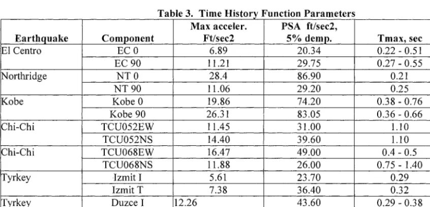
In figs. 3-5, the displacement of the crucial joints under Kobe, Turkey and Chi-Chi earthquakes respectively are shown. From these displacements, we can see that the relative displacement of different building blocks could reach the limiting points (e.g. the clearance distance between these blocks).
There are significant relative displacements between the adjacent joints of different parts in both EW-direction and NS- direction. When the adjacent parts move toward each other, because the clearance distance between the adjacent parts in NS- direction is only 1.125 ft, pounding may occur at these joints. When the adjacent parts move outward each other, it could lead to large deformation of the nonstructural component (e.g. water and gas pipelines) crossing these joints.
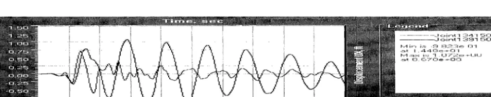
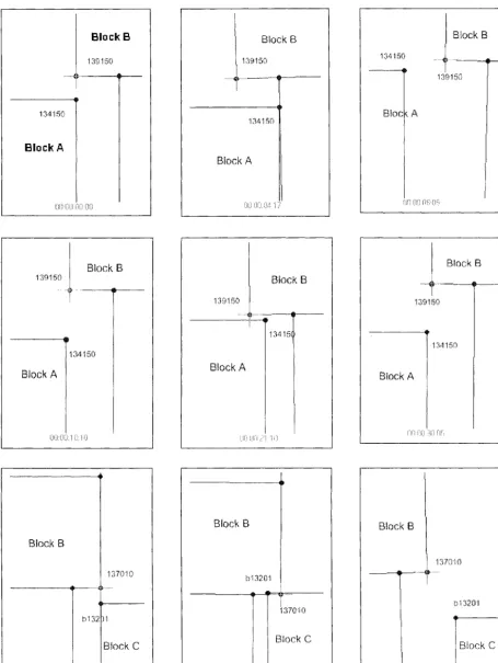
The mutual positions of the building blocks on the different time of earthquake shown on the fig. 6, where show crucial joint location on 13 floor level at E1 Centro earthquake. As it could be seen, on 3.07 sec of E1 Centro earthquake the collision of blocks A and B is occurring. After this on 4.17 sec of earthquake the collision between blocks B and C is happening. The same situation exists for different earthquakes.
m N
... . . . o,' .... i i ... •
~ , i~ ~ ! i . i i i ! i ! i ~,i
I--,#I i r-i i ~-=: - I . ~ L--I ~ e -i-- i.-_i I[I
a l . , - ~ . - 3 .'-~_-: I_ 7 o -~-- L 7 C I
• ~ , I : 1 . "--"~- , " ~ : . ~ _ , - ~ . . - - , - ' ~ ' 1
Fig. 3.a. Kobe, 13 floor level. Displacement UX of the Block A (joint 134150) and Block B (joint 139150)
... ~ ... ~ ... iII~ ... - ~ - ... i ... ~ ... ~ . . . ) ... ) ... | " d , : . i n * 1 =.--_--I 4 1 5 0 |
i ) i [ ~ I A ~ ) ) ) ) I ~ o i n t l 3 9 1 5 0
i m m m ~ t , , . . . . , T n ~ ) ) m , 1 1 , ":. :--- " -: - - ) . : - , . 2 . ,._ : ~ ..=_;,-: ,- ... ~ - .,H . . . -.-/~ . . . i ~ . . .
Fig. 4a. Chi-Chi, TCU052, 13 floor level. Displacement UX of the Block A (joint 134150) and Block B (joint 139150)
H
,
- J o i n t l 3 7 0 1 0,_1 , - , i r - , t B 1 :_--: 2 E l 1
I'-.-1 i n - , i ~ : - 4 . ~ - - I ; ~ ' 2 e + O C I
1 " - . 4 . = , x i : ~ ~ Z _ ; . ~ ; ' ~ ; ~ e + r L ~ C m
.~ ~ 1 . 7 7 5,-: -+- 0 -I
I
. . . i . . . IFig. 4b. Chi-Chi, TCU052, 13 floor level. Displacement UY of the Block B (joint 137010) and Block C (joint B13201)
. . . i
[
i _
. . . i
. . . !
-i
• J o i n t l 3 7 0 1 0 .I c ~ i r ~ t E ~ • 1 Z-_1:3[: I~J 1 I".-t i t , i:s-" - 1 . 7 8 B e + l - t o O .:z~l: .,c.._~. 2 1 ~ i l O e + O i - i
. ~ m: 7 _ :--: 0 0 ~ - , - 0 n
Fig. 5 a. Kobe, 13 floor level. Displacement UY of the Block B (joint 137010) and Block C (joint B13201)
~w~,-= ~:,~i . . . i f'l i - - - -A- i ... i ... i ... [ ... i ... i .... i- m
- , , ~ . ~ - . . . . ~ I ) / ... ~ .... i' !i--Y i ---~~" .... ~ g / ~
- - , ~ ~ : ~ ~ i ) ) ) i ~ ! ~ ~ i I
• ::~ ) ) ) i ( ) ) j ~ ~.m
J o i n t l 3 7 0 1 0 , = ~ i r m t E " 1 3 2 0 1
I"-,-1 i n i ~-: - 2 . I 6 I e -m- I - I 0
. ~ l : 8 . 7 6 0 ~ - ~ - - - ~ - 0 n I~.-1 ~ - J x i~_: 2 _ O 5 4 .~-~_.-~-OCI
a l : 6 . I - Z - _ - ; 5 0 e - * - O I - I
Block B
, !39150 !
i
134,'150
Block A
I
l
B!ock B
1 3 9 1 5 0
!
.... e . . .
I /
134 ! 50
Biock A
! 34 ! 50
B!o(
J B!ock B
t
f
... @ ...
!
1 3 9 1 5 0
! 39 ! 50
Block A
Biock B
!
t
1 3 4 1 5 0
IL
CC: ,7::L I i::i: i ,:i
B+ock B
1 3 9 1 5 0
i
Bgock A
{j~:i Ufi ,/i i i:l
Brock B
!
! 39 ! 5O
1 3 4 1 5 0
Block A
!-~i~ - i-H:I ,!!',i[i l-!Fi
Block B
! 3 7 0 : i 0
i
I
b i 3 1
Biock
i3i~i: LtL! !\~i~i: i:iii
Block B
b ! 3 2 0 !
0 t:i:iZi 0:0 .i!',: U Z
Block B
, 1 3 7 0 1 0
I
iAj:i ,i:i i j4 2ii{;
b :43201
l BUock C
BUILDING R E H A B I L I T A T I O N S C H E M E S
As discussed, under seismic loading, significant relative displacements among middle and wing building blocks may take place. These relative displacements may lead to severe damage of horizontal structural, non-structural components and equipment, especially piping system crossing different parts of the building. The general rehabilitation measures for the piping system itself, such as anchoring, could not prevent damage under such large displacement. To avoid pounding between the towers and protect the piping and equipment, seismic rehabilitation must be applied to the structure to reduce the relative displacement between different parts. Based on the character of the three towers, two rehabilitation methods have been used: Damping approach and Stiffness Approach. These two methods are analyzed as per FEMA 273/275 [1,2], in which E1 Centro, Kobe and Northridge ground motions are used as the input. As the previous analyses, the study was conducted in SAP2000 software.
D A M P E R A P P R O A C H
For damper approach passive fluid device is a typical choice. The viscous fluid device and the visco-elastic fluid devices are used for analysis. Although damper could be installed in any position in the building, the most convenient way is to install the dampers at the same position of the sliding joints. In each floor level, four dampers are installed in the X- direction sliding joint position and two dampers are installed in the Y-direction sliding joint position. Totally, there are 52 dampers in the X-direction and 26 dampers in the Y-direction.
The damping force model for viscous fluid device can be expressed as F - C01/) ~ s g n ( / ) )
where: Co = The damping coefficient for the device. Co = 600 - 3000 kips x sec/ft - Velocity exponent for the device, a = 1
= The relative velocity between each end of the device.
To investigate the effect of viscous device the time-history analysis was conducted. The results of displacement time history (for C0=3000) are shown in Table 5.
Table 5. Maximum Relative Displacements Between Block A, Block B and Block C (ft)
X-Direction Y-Direction
Location El Centro Kobe Northridge El Centro Kobe Northridge
A - B 0.061 0.0494 0.0488 0.0359 0.0468 0.0419
B - C 0.0281 0.0254 0.0215 0.0315 0.0278 0.0356
As the analysis shown, relative displacements between towers are very small under strong earthquake ground motions. V I S C O , E L A S T I C FLUID DEVICE
The visco-elastic fluid device could be modeled by using a spring and dashpot in series or in parallel. In this paper, only the parallel model is considered.
Unlike the viscous fluid device, both coefficient Co and K are important parameters for the damping device force. To compare with different approach, Co = 1500 and K =10000 kips/ft was used. Table 6 shows the maximum relative displacement of these joints at roof level.
Table 6. Maximum Relative Displacements Between Block A, Block B and Block C (ft)
X-Direction Y-Direction
Location El Centro Kobe Northridge E! Centro Kobe Northridge
A B 0.0640 0.0716 0.0853 0.0675 0.0729 0.0673
B - C 0.0264 0.0224 0.0237 0.0430 0.0507 0.0528
The relative displacement results of using visco-elastic devices are very similar to those using viscous fluid device. STIFFNESS A P P R O A C H
For this kind of structural rehabilitation, because all separate part of the hospital building are connected as single structure, the dynamic properties of the building changes greatly: compare with existing design the fundamental period of free vibration reduced from 4.77 to 2.58 sec. These changes mean that the flexible middle tower, block B, has been restrained by side wing blocks A and B. Table 7 shows the maximum relative displacement of these joints at roof level.
It is seen that the relative displacement between part A, part B and part C is very small in both the X and the Y directions. There is no collision possibility of the different parts of building towers by using this retrofit scheme.
Table 7. Maximum Relative Displacements Between Block A, Block B and Block C (ft)
X-Direction Y-Direction
Location El Centro Kobe Northridge El Centro Kobe Northridge
A - B 0.0011 0.0011 0.0013 0.0269 0.0294 0.0276
B - C 0.001 0.0013 0.0012 0.024 0.0264 0.0264
C O M P A R I S O N OF D I F F E R E N T R E H A B I L I T A T I O N A P P R O A C H E S
Based on the limited analyses, we conclude that for the relative displacement between towers, the stiffness approach is better retrofit strategy.
Using dampers between the towers to reduce the relative displacement could not receive best result. Although the relative displacement in the pounding direction could be reduced to 50%, the relative displacement in the sliding direction could not be reduced much. This means the passive energy dissipation device between the buildings can only absorb part of the kinetic energy. To further reduce the relative displacement and drift ratio, more devices should be used in the lateral load carrying system to control the single building's floor response. To reduce the relative displacement in the sliding direction, the different buildings should have similar dynamic property in that direction. Although damping approach does not produce the best result, it has its own advantage: the dynamic properties will not change as much as the stiffness approach for each individual building block. Therefore, there is no need to re-analyze and possibly re-design the total structure.
The stiffness approach gives better result to reduce the relative displacement in both the pounding direction and the sliding direction. But this approach also has deficiency: the separated buildings form a large building and the dynamic property changes entirely. The structural members need to be recalculated to decide whether it could bear different seismic load and wind load. The stiffness approach should also consider the effect of temperature change, which may cause extra stress of the structural elements.
The analysis provided in this paper mainly addresses the issue of potential pounding problems. Using energy dissipation devices or the stiffness enhancement approach may involve many other issues such as design performances. Equivalent response reduction is due to increased damping ratio, and various modeling assumptions in FE Model. Discussions on these related topics can be found in [4, 5 and 6].
CONCLUSION
1. The comprehensive dynamic analysis of a complex irregular structural system with unattached building components is conducted by using SAP2000. Such analysis led to a better understanding of the dynamic responses of the different parts of the complex structure under different earthquake loading conditions.
2. Results show that under moderate and strong earthquakes, different sections of the building will collide and damages can occur.
3. To reduce the relative displacement and prevent damage of the structure, various retrofit strategies based on damping and/or stiffness approaches may be used.
R E F E R E N C E S
1. FEMA 273, NEHRP Guidelines for the Seismic Rehabilitation of Buildings, Federal Emergency Management Agency, Oct., 1997.
2. FEMA 274, NEHRP Commentary on the Guidelines for the Seismic Rehabilitation of Buildings, Federal Emergency Agency, Oct, 1997.
3. Lee, G.C., Tong, M. and Wu, Y. H., "Some Design Issues for Building Seismic Retrofit Using Energy Dissipation Devices," Structural Engineering and Mechanics, An International Journal, Taejon, Korea, 2000.
4. Constantinou, M. C., Soong, T. T. and Dargush, G. F., Passive Energy Dissipation Systems for Structural Design and Retrofit, An NCEER Monograph, Department of Civil Engineering, SUNY at Buffalo, NY 14260, June 1996.
5. Lee, G. C., Wu, Y.H. Tong, M. and Liang, Z., "Seismic Design Considerations of Structures with Supplemental Protective Devices: Effects of Damping Force on Column Strength," Proc. Int. Workshop on Seismic Isolation, Energy Dissipation and Structural Control, Quanzhou, May 1999.