Optimization of Surface Finish and Material
Removal Rate with Different Insert Nose Radius
for Turning Operation on CNC Turning Center
Rishu Gupta1, Ashutosh Diwedi2
1
PG student Mechanical Engineering Vindhya Institute of Technology and Science, Satna India,
2
Asst. Professor and HOD, Department of Mechanical Engineering, Vindhya Institute of Technology and Science,
Satna, India.
ABSTRACT— In this research work the effect of insert nose radius and machining parameters including cutting
speed, feed rate and depth of cut on surface roughness and material removal rate (MRR) in a turning operation are investigated by using the Taguchi optimization method. A three level four parameter design of experiment, the signal-to-noise (S/N) ratio are employed to the study the performance characteristics in the turning of Aluminium Alloy 6061 using nose radius of 0.4, 0.8 and 1.2 mm carbide inserts on CNC turning centre. The conclusions revealed that the feed rate and nose radius were the most influential factors on the surface roughness and Material Removal Rate (MRR) in CNC turning process is greatly influenced by depth of cut followed by cutting speed. For simultaneous optimization of Surface roughness (Ra) and material removal rate (MRR) depth of cut is the most significant parameter affecting the performance followed by the nose radius.
KEYWORDS: Inserts,Taguchi,S/N ratio, Aluminium, MRR, Surface Roughness, Nose radius.
I. INTRODUCTION
Turning is the removal of metal from the outer diameter of a rotating cylindrical work piece. Turning is used to reduce the diameter of the work piece, usually to a specified dimension, and to produce a smooth finish on the metal. Turning is the machining operation that produces cylindrical parts. The three primary factors in any basic turning operation are speed, feed, and depth of cut. Other factors such as kind of material and type of tool have a large influence, of course, but these three are the ones the operator can change by adjusting the controls, right at the machine. Tool geometry parameters play an important role in determining the overall machining performance, including cutting forces, tool wear, surface finish, chip formation and chip breaking. Several angles are important when introducing the cutting tool's edge into a rotating work piece. These angles include the angle of inclination, rake angle, effective rake angle, lead or entry angle, and tool nose radius.
On the strength of the review of work done by previous researchers [1- 13], it is found that a considerable amount of work has been carried out by previous investigators for modeling, simulation and parametric optimization of surface properties of the product in turning operation. Issues related to tool life, tool wear, cutting forces have been addressed to. But a very little work has been found in uses of different inserts with different nose radius as a parameter for optimizing the surface properties.
This study demonstrates detailed methodology of the proposed optimization technique which is based on Taguchi method; and ranks the parameters namely cutting speed, feed, depth of cut and nose radius of inserts through S/N ratio. MRR of a turned product along with surface finish of work piece have been optimized.
II. MATERIALS AND METHODS
A. CNC Turning Centre
ACE Designers Ltd. make CNC turning centre with Fanuc Oi-mate-TD controller is used to carry out the experimentation.
Table 1 Specifications of CNC turning center Max. Turning diameter 190 mm
Max. Turning length 200 mm
Chuck Size 135 mm
Spindle Speed 50- 4000 rpm
Spindle motor power 5.5 kW/ 3.7 kW
B. Selection of Cutting Tools
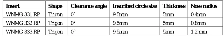
The cutting tool selected for present work is carbide inserts. The inserts (ANSI coding) used in present work are WNMG 331 RP (a), WNMG 332 RP (b) and WNMG 333 RP (c).
Table 2: The tool geometry of the inserts used
Insert Shape Clearance angle Inscribed circle size Thickness Nose radius
WNMG 331 RP Trigon 0° 9.5mm 5mm 0.4mm
WNMG 332 RP Trigon 0° 9.5mm 5mm 0.8mm
WNMG 333 RP Trigon 0° 9.5mm 5mm 1.2 mm
C. Selection of Work piece Material
The work piece material used for current work is Aluminium Alloy 6061 circular bars of diameter 25mm and length 50mm.
D. Process Parameters and Levels used in the Experiment
The machining process on CNC lathe is programmed by cutting speed, feed and depth of cut. The parameters and levels used in the experiment are shown in Table 3.
Table 3: Process parameters and levels
Levels Variables
Cutting Speed, m/min (A)
Feed, mm/rev (B)
Depth of cut, mm (C)
Nose radius, mm (D)
Level 1 100 0.25 1 0.4
Level 2 150 0.3 1.5 0.8
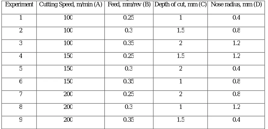
E. Design Matrix
In the present work there are three levels and four parameters. According to Taguchi approach L9 orthogonal array has been selected. So, according to Taguchi L9 array design matrix of variables are formed.
Table 4: Design matrix of variables
Experiment Cutting Speed, m/min (A) Feed, mm/rev (B) Depth of cut, mm (C) Nose radius, mm (D)
1 100 0.25 1 0.4
2 100 0.3 1.5 0.8
3 100 0.35 2 1.2
4 150 0.25 1.5 1.2
5 150 0.3 2 0.4
6 150 0.35 1 0.8
7 200 0.25 2 0.8
8 200 0.3 1 1.2
9 200 0.35 1.5 0.4
III. RESULTS AND DISCUSSIONS
A. Material Removal Rate (MRR)
Initial and final weights of work pieces are noted using digital weighing machine. Machining time is also recorded. The density of the Aluminium is taken as 2.7 x 10⁻³ g/mm3.
B. Sur face Roughn ess (Ra )
Surface Roughness measurement has been done using a portable stylus-type profilometer, Mitutoyo- Surftest SJ- 201P/M. The evaluation length of 2.5 mm is used to measure response Ra value in µm.
C. Respon se Table
Response table for the experimental design matrix is shown in table 5.
Table 5: Response table of Ra and MRR
Exp. A B C D Ra MRR
1 100 0.25 1 0.4 3.25 10591.34
2 100 0.3 1.5 0.8 3.72 21369.38
3 100 0.35 2 1.2 4.65 27777.78
4 150 0.25 1.5 1.2 3.81 19779.39
6 150 0.35 1 0.8 3.97 16653.81
7 200 0.25 2 0.8 4.02 32354.2
8 200 0.3 1 1.2 4.35 16138.9
9 200 0.35 1.5 0.4 3.99 27204.3
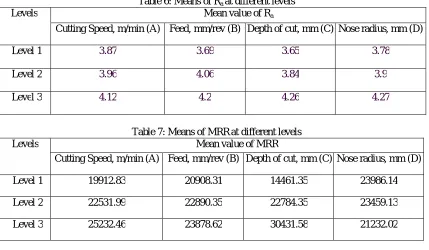
D. Analysis of Single Respon se Stage
The optimal settings and the predicted optimal values for surface roughness and MRR are determined individually by Taguchi’s approach. Table 8 shows these individual optimal values and its corresponding settings of the process parameters for the specified performance characteristics. It is observed that the feed is most significantly influences the Ra followed by nose radius. In case of MRR, depth of cut is the most significant parameter followed by cutting speed.
Table 6: Means of Ra at different levels
Levels Mean value of Ra
Cutting Speed, m/min (A) Feed, mm/rev (B) Depth of cut, mm (C) Nose radius, mm (D)
Level 1 3.87 3.69 3.65 3.78
Level 2 3.96 4.06 3.84 3.9
Level 3 4.12 4.2 4.26 4.27
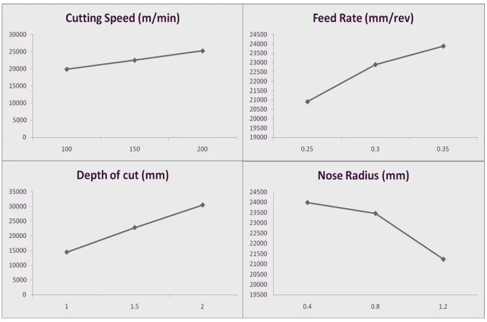
Table 7: Means of MRRat different levels
Levels Mean value of MRR
Cutting Speed, m/min (A) Feed, mm/rev (B) Depth of cut, mm (C) Nose radius, mm (D)
Level 1 19912.83 20908.31 14461.35 23986.14
Level 2 22531.99 22890.35 22784.35 23459.13
Level 3 25232.46 23878.62 30431.58 21232.02
Table 8: Individual optimal values and corresponding setting of process parameters
Performance characteristics Optimal parameter level Optimum level
Ra (µm) A1-B1-C1-D1 3.25
MRR (mm3/min) A3- B3-C3-D1 31256.94
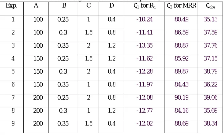
F. Analysis of Multi- r espon se stage
Larger the better S/N ratio for MRR
From the utility concept, the multi-response S/N ratio of the overall utility value is given by
Where W1 & W2 are the weights assigned to the Ra and MRR. Assignment of weights to the performance characteristics are based on experience of engineers, customer’s requirements and their priorities. In the present work equal importance is given for both Ra and MRR. Therefore W1 & W2 = 0.5.
The optimal combination of process parameters (A3-B3-C3-D1) for simultaneous optimization of Surface roughness (Ra) and material removal rate (MRR) is obtained by the mean values of the multi-response S/N ratio of the overall utility value are shown in Table 10. According to the Table 10 for the results of S/N ratio multiple performance characteristics, depth of cut is the most significant parameter affecting the performance followed by the nose radius. The percent contribution of the feed rate is lower and the cutting speed is much lower.
Table 9: Design matrix with multi- response S/N ratio
Exp. A B C D η1 for Ra η2 for MRR ηobs
1 100 0.25 1 0.4 -10.24 80.49 35.13
2 100 0.3 1.5 0.8 -11.41 86.59 37.59
3 100 0.35 2 1.2 -13.35 88.87 37.76
4 150 0.25 1.5 1.2 -11.62 85.92 37.15
5 150 0.3 2 0.4 -12.28 89.87 38.79
6 150 0.35 1 0.8 -11.97 84.43 36.22
7 200 0.25 2 0.8 -12.08 90.19 39.06
8 200 0.3 1 1.2 -12.77 84.16 35.69
9 200 0.35 1.5 0.4 -12.02 88.69 38.34
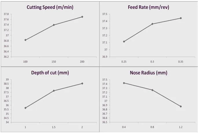
Table 10: Mean value of ηobs at different levels
Levels Mean value of ηobs for process parameters
Cutting speed (m/min) Feed (mm/rev) Depth of cut (mm) Insert used
Level 1 36.83 37.11 35.68 37.42
Level 2 37.39 37.36 37.69 37.25
G. Interpretation of Plots
The data is plot and developed. These results are analyzed using S/N ratio for the purpose of identifying the significant factors which affect the surface roughness and material removal rate. The plots show the variation of individual response with the four parameters i.e. cutting speed, feed, depth of cut and nose radius separately. In the plots, the x-axis indicates the value of each process parameter at three level and y-x-axis the response value. Figure 1 shows the main effect plot for MRR. It is observed that the maximum MRR is obtained at the 200 m/min of cutting speed, 0.35mm/rev of feed, 2 mm depth of cut and 0.4 mm nose radius. Figure 2 shows the main effect plot for surface roughness. It is observed that the maximum surface finish or minimum roughness is obtained at the 100 m/min of cutting speed, 0.25mm/rev of feed, 1 mm depth of cut and 0.4 mm nose radius. Figure 3 shows the optimum levels of process parameters for the multi-response optimization are thus determined to be 200 m/min of cutting speed, 0.25mm/rev of feed, 2 mm depth of cut and 0.4 mm nose radius.
Fig. 2: Response Graph for Ra
Fig. 3: Multi- Response S/N Ratio Graph
IV. CONCLUSIONS
The analysis of the experimental observations highlights that MRR in CNC turning process is greatly influenced by depth of cut followed by cutting speed.
It is observed that the feed is most significantly influences the Ra followed by nose radius.
For simultaneous optimization of Surface roughness (Ra) and material removal rate (MRR) depth of cut is the most significant parameter affecting the performance followed by the nose radius.
REFERENCES
[1] Feng, C.X. and Wang X, Development of empirical models for surface roughness prediction in finis turning. International Journal of Advanced Manufacturing Technology; 2002, Vol. 20, pp.348-356.
[2] Lambert, B.K.; Determination of metal removal rate with surface finish restriction. Carbide and tool Journal, May – June : 16-19, 1983. [3] Ho SY , Lee KC, Chen SS, Ho SJ; Accurate Modeling prediction of surface roughness by computer vision in turning operation using an
adaptive neuro- fuzzy inference system. Int J Mach Tools Manuf, 2002; 42:1441-1446.
[4] Malakooti B. and Raman V.; An Interactive Multi –Objective artificial neural network approach for machine setup optimization, Journal of Intelligent Manufacturing, 2000, Vol. 111, pp 41-50.
[5] Rasch and Roistadas; Series of finish turning tests under variation of parameters : Material quality ., Tool quality , Tool nose radius , feed speed and cutting time. Journal of material processing technology, 1971, Vol-132, 203-214.
[6] Tian-Syung Lan and Ming-Yung Wang; Competitive parameter optimization of multi-quality CNC turning; The International Journal of Advanced Manufacturing Technology; April 2009, Volume 41, Issue 7-8, pp 820-826
[7] Zhang Xueping, Gao Erwei and C. Richard Liu; Optimization of process parameter of residual stresses for hard turned surfaces; Journal of Materials Processing Technology; Volume 209, Issue 9, 1 May 2009, Pages 4286–4291
[8] Süleyman Neşeli, Süleyman Yaldız and Erol Türkeş; Optimization of tool geometry parameters for turning operations based on the response
surface methodology; Measurement; Volume 44, Issue 3, March 2011, Pages 580–587
[9] Ahmet Hascalik and Ulas Cavdas; Optimization of turning parameters for surface roughness and tool life based on the Taguchi method; The International Journal of Advanced Manufacturing Technology; September 2008, Volume 38, Issue 9-10, pp 896-903
[10] Chorng-Jyh Tzeng, Yu-Hsin Lin, Yung-Kuang Yang and Ming-Chang Jeng; Optimization of turning operations with multiple performance characteristics using the Taguchi method and Grey relational analysis; Journal of Materials Processing Technology; Volume 209, Issue 6, 19 March 2009, Pages 2753–2759
[11] Anil Gupta, Hari Singh and Aman Aggarwal; Taguchi-fuzzy multi output optimization (MOO) in high speed CNC turning of AISI P-20 tool steel; Expert Systems with Applications; Volume 38, Issue 6, June 2011, Pages 6822–6828
[12] Raju Shrihari Pawade and Suhas S. Joshi; Multi-objective optimization of surface roughness and cutting forces in high-speed turning of Inconel 718 using Taguchi grey relational analysis (TGRA); The International Journal of Advanced Manufacturing Technology; September 2011, Volume 56, Issue 1-4, pp 47-62