Seismic-upgrading of Existing Stacks by Structural Control using Oil Dampers
Ryuu Shimamoto1), Takafumi Hiraki1), Fukashi Mori2), Eiji Ohara3) and Haruhiko Kurino4)
1) Civil & Architectural Engineering Dept., Chubu Electric Power Co., Inc. Nagoya, Japan 2) Hamaoka Nuclear Power Station, Chubu Electric Power Co., Inc. Shizuoka, Japan 3) Nuclear Power Department, Kajima Corporation, Tokyo, Japan
4) Kobori Research Complex, Kajima Corporation, Tokyo, Japan
ABSTRACT
This paper presents a seismic-upgrading project for 100m-high steel stacks in an existing nuclear power station utilizing a structural control technique. For this upgrading, we reexamined seismic loads and set up a new target earthquake that exceeded the original design loads. First, we examined the possibility of conventional reinforcement by building a new supporting truss-tower to surround the existing stack. However, it became apparent that several problems would remain unsolved with such a simple technique. Thus, we decided to employ a structural control that would reduce the response vibration. In order to improve the structural damping as well as strength, we planned to link the stack with the supporting truss-tower via oil dampers. The shape of the supporting truss-tower and the allocation and parameter of the dampers were carefully examined considering each unit’s individual situation. Numerical analysis results showed remarkable response reduction effects that could not be realized by conventional reinforcement. This upgrading construction work is to be carried out while the station is running, and this project will become the first full-scale application of structural control technology in a nuclear power station facility in Japan. This paper outlines the upgrading plan, simulation results and the newly developed oil damper.
INTRODUCTION
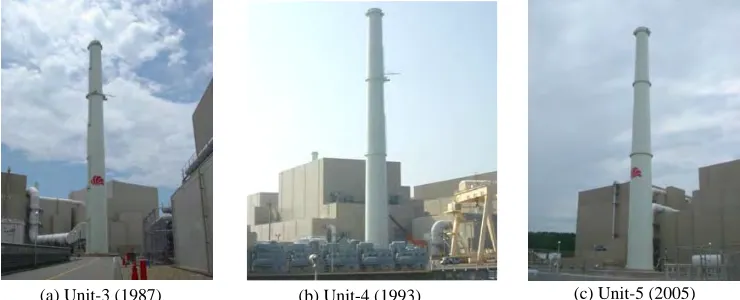
Presented here is a seismic-upgrading project for steel stacks in an existing nuclear power station, utilizing structural control technologies. The target Hamaoka nuclear power station consists of five reactor buildings, and three stacks (units-3, 4 and 5) are included in this upgrading project. Fig. 1 shows photos of the existing tube-shaped stacks, which are all about 100m high and free-standing without any supporting frames. Although the seismic safety was thoroughly examined when these units were designed, it has become very important to improve the station’s safety by utilizing up-to-date knowledge and technologies, because the target nuclear power station is located in an area where a severe earthquake is expected at some time in the future.
For this project, we reexamined the seismic loads, and set up a new target earthquake for structural design. This target design earthquake load is much stronger than the original design loads, and this made the upgrading structural design very challenging. First, we examined the possibility of conventional reinforcement by building up a new supporting truss-tower around the existing tube-shaped stack. However, it became apparent that several difficult problems would remain unsolved with such a simple technique. For example, the layout of the supporting truss-tower bases is severely constrained by several obstacles such as underground tubes. As a result, the available width between the bases is limited so small that the stiffness of the supporting truss-tower could not be enough to reduce the response of the existing stack within its allowable values. In addition, the estimated response of the supporting truss-tower would be very large, making it difficult to design the tower. Thus, structural control techniques that could reduce the seismic response became the key to solving these difficult problems.
Fig. 1 Photos of Existing Stacks (Operation-start year)
In order to not only improve the structural strength, but also augment the structure’s damping, we planned to link the existing stack with the supporting truss-tower via oil dampers. The allocation and number of dampers were carefully examined to meet the required conditions. In addition, the height of the supporting truss-tower also became a parameter in controlling its response. Considering these complex given conditions, the upgrading design was optimized reflecting each unit’s situation. Numerical analysis results showed remarkable response reduction effects that could not be realized by conventional reinforcement. However, they also clarified that new oil damper would need to be developed because the required specifications were beyond the capability of existing product.
This project will be the first full-scale application of structural control technology to an actual nuclear power station facility in Japan. This paper first outlines the upgrading design including optimization process of determining damper parameters. Next, it presents simulation results that show the response reduction effects of structural control. In addition, the newly developed oil damper that meets the required stringent specifications is presented.
TARGET EARTHQUAKE
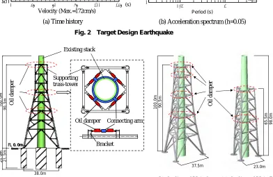
Fig. 2 shows a newly-set-up target earthquake for this upgrading project. Fig. 2(a) shows a time history which is evaluated at bedrock (FL-20m, Vs=700m/s). The peak acceleration is 1040cm/s2 and the peak velocity is 172cm/s. Fig. 2(b) shows an acceleration response spectrum (damping ratio h=0.05). The acceleration spectrum of an original design earthquake, which was used for designing the existing stacks, is also shown in Fig. 2(b) for comparison. The spectrum of the new target earthquake is about twice as strong as that of the original design earthquake, which makes this seismic upgrading design very challenging.
0.1 1
0 1000 1000 2000 2000 3000 3000
0 1000 2000 3000
65.5m
23.0m
98.0m
100.0m
37.5m
90.5m
(a) Time history (b) Acceleration spectrum (h=0.05)
Period (s)
Target earthquake for this project
Original design earthquake (cm/s2
)
Fig. 2 Target Design Earthquake
Fig. 3 Upgrading Design Concept
(a) Damper installation for Unit-4 (b) Outline of Unit-3 (c) Outline of Unit-5
(s)
(c
m/s
2 )
0 25 50 75 100 125
-1500 0 0 1500 1500
-1500 0 1500
0 25 50 75 100 125
-200 0 0 200 200
-200 0 200
(s)
(c
m/s
)
Acceleration (Max.=1040cm/s2)
Velocity (Max.=172cm/s)
Oil da
mper
Oil da
mper
Oil damper Connecting arm
Bracket
38.0m
Existing stack
STRUCTURAL DESIGN UTILIZING OIL DAMPERS
Structural Design Concept
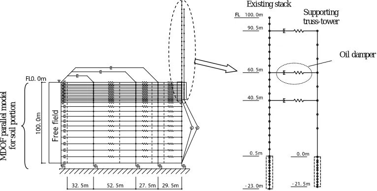
Fig. 3 describes a concept for upgrading structural design using oil dampers. Fig. 3(a) shows a detailed damper installation for Unit-4. The existing tube-shaped steel stack is about 100m high with a diameter from 8.8m at the base to 5.6m at the top. We planned to build a new supporting truss-tower 90.5m high around the existing stack, and to connect the two structures via oil dampers. The details of the joint part are also described in Fig. 3(a). The damper is inserted between a connecting arm attached to the existing stack and a bracket of the new supporting truss-tower. We arranged three connecting levels (FL+90.5m, 60.5m and 40.5m) in considering various obstacle attachments of the existing stack as well as the control effect of the oil dampers. The oil damper generates a reaction force against a relative motion between the existing stack and the supporting truss-tower, and augments the damping effect to both structures to reduce the response vibration.
Fig. 3(b) and (c) also outline Units 3 and 5. Because of the constraints on the base arrangement imposed by obstacles such as buried tubes, the supporting truss-tower for these two units adopts triangle-shape plan. The supporting truss-tower for Unit-5 was made lower than those of the other units to control the response of the supporting truss-tower. Because the existing stack of Unit-5 is relatively stronger than the other units, we decided that the lowering the supporting truss-tower is rational. However, the number of the connection levels for Unit-3 was increased because its existing stack was less strong.
The damper parameters were determined considering both the damping ratio augmented to the structures and the response of the damper portion. The following outlines the scheme for determining the damper parameters, focusing on Unit-4 as an example.
Study on Damper Parameters
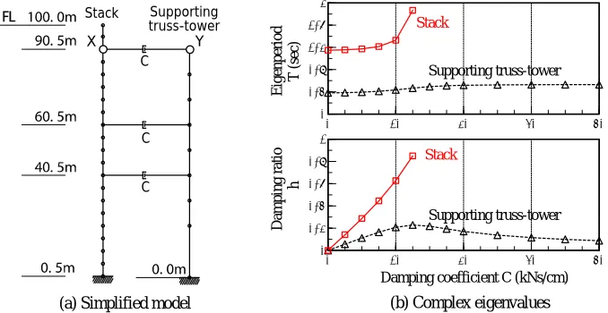
Fig. 4(a) shows a simplified 2-dimensinal vibration model of Unit-4 used for this study. The existing stack and the supporting truss-tower are modeled as lumped-mass bending-shear beam elements. The oil damper at each connecting level is expressed as a dashpot with damping coefficient C. Although it is known that the dynamic characteristic of an oil damper is expressed as a Maxwell model, we simply model it as a dashpot here because the effect of the stiffness is very small. We, however, consider its stiffness in the seismic response analyses shown in a later chapter. The natural periods of the existing stack and the supporting truss-tower without oil dampers are 1.15s and 0.38s, respectively. If the damper is replaced by a rigid spring, the period of the linked structure becomes 0.52s.
In order to grasp the relation between the damping coefficient of each damper and the vibration characteristics of the structure, we conducted complex eigenvalue analyses. For simplicity, we assumed that the damping coefficients at each connecting level are equal, and that the original damping of both structures is zero. Fig. 4(b) shows the damping ratio and the eigenperiod of the fundamental modes obtained by the complex eigenvalue analyses. The horizontal axis shows a damping coefficient C at each level in Fig. 4(a). From Fig. 4(b), the following are recognized:
1. When C is smaller than about 10kNs/cm, two independent eigenvalues are obtained as fundamental modes. This means that the interaction between the existing stack and the supporting truss-tower is small. In this region, the damping ratios h of both structures increase in proportion to C.
2. When C becomes 12.5kNs/cm, the stack’s damping ratio reaches 1.0 and its eigenperiod suddenly becomes longer because of the relationω 2ω
1
'= −h . The damping ratio of the supporting truss-tower also becomes a maximum.
X Y
C
C C
Stack Supporting
truss-tower
Fig. 4 Simplified Model and Complex Eigenvalues of Unit-4
(b) Complex eigenvalues
0 10 20 30 40
0 0.4 0.8 1.2 1.6 2
0 10 20 30 40
0 0.2 0.4 0.6 0.8 1
Eigenp
eriod
T (s
ec)
Damping coefficient C (kNs/cm) Stack
Supporting truss-tower
Damping r
atio
h
Stack
Supporting truss-tower
3. When C is larger than 12.5kNs/cm, only one eigenvalue remains as a fundamental mode because the stack and the supporting truss-tower strongly interact with the oil dampers. If C increases much more, the damping ratio gradually decreases and the eigenperiod approaches the value for the case where the two structures are rigidly linked.
Therefore, it seems logical to set C for each level as 12.5kNs/cm if we focus on the damping augmentation of the fundamental vibration modes. However, we should take into account not only the damping augmentation but also the response of the damper portion in order to avoid the damper’s specification becoming unrealistic.
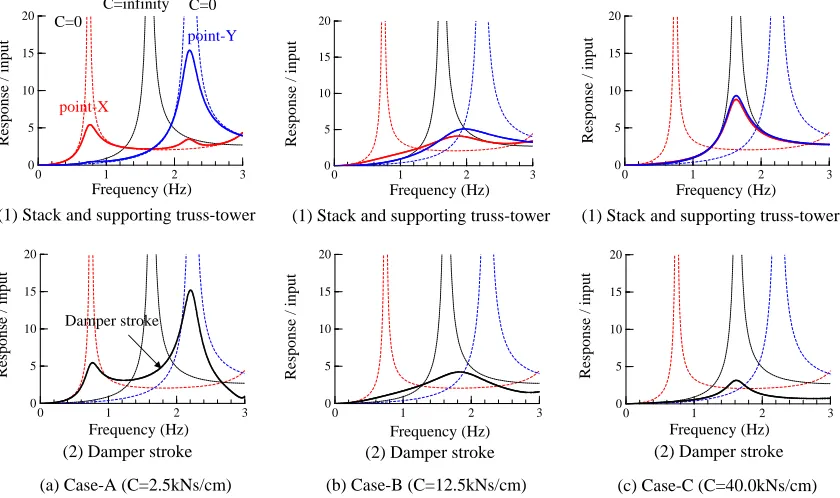
Fig. 5 shows resonance curves corresponding to three typical values of C in Fig. 4(b). The upper figures (1) show the displacement amplitudes of the stack and the supporting truss-tower (point X and Y in Fig. 4(a)). The lower figures (2) show the displacement amplitude between point X and Y, which is equivalent to the damper stroke. From the viewpoint of response reduction of the structures, case-B seems to have the best setting. However, the resonance curve of damper response still extends over a wide frequency range. On the other hand, the damper response is kept small in case-C because the interaction between the two structures becomes stronger than in case-B. Compared with the case-B, the peak of the resonance curves of the stack and the supporting truss-tower becomes a little higher. This, however, does not mean that the structure’s response increases rapidly. Therefore, we decided to set the damping coefficient at each level to around 30kNs/cm considering not only structural response reduction but also damper stroke control.
Determined Damper Parameters
Table 1 shows the finally determined specifications of the oil damper. From the viewpoint of maintenance, it is rational to use the same device for all connecting levels of all units, but because the required strokes and velocities are very different, we chose two different specifications. The damper distribution is shown in Table 2, and the eigenperiods and damping ratios evaluated by complex eigenvalue analyses for these final settings are shown in Table 3. As shown in a later chapter, these two types of dampers have the same force capacity but different stroke capacities and damping coefficients. The damping coefficient, or velocity capacity, is determined by the total capacity of housed valves. The two kinds of dampers, shown in Table 1, house the same sized valves, but different numbers of valves. For efficient development and future maintenance, using common components has several advantages.
Type Damping coefficient Stiffness Permissible velocity Stroke
L 5.0kNsec/cm 80kN/mm 180cm/s ±300mm
M 7.5kNsec/cm 110kN/mm 120cm/s ±200mm
Table 1. Damper Specifications
0 1 2 3
0 5 10 15 20
0 1 2 3
0 5 10 15 20
0 1 2 3
0 5 10 15 20
0 1 2 3
0 5 10 15 20
0 1 2 3
0 5 10 15 20
Fig. 5 Resonance Curves with Various Damper Settings for Unit-4
(a) Case-A (C=2.5kNs/cm) (b) Case-B (C=12.5kNs/cm) (c) Case-C (C=40.0kNs/cm) (2) Damper stroke
(1) Stack and supporting truss-tower
Frequency (Hz) Frequency (Hz)
Response /
input
Response /
input
(2) Damper stroke (1) Stack and supporting truss-tower
Frequency (Hz) Frequency (Hz)
Response /
input
Response /
input
(2) Damper stroke (1) Stack and supporting truss-tower
Frequency (Hz) Frequency (Hz)
Response /
input
Response /
input
point-X
point-Y
C=0
C=infinity C=0
Damper stroke
0 1 2 3
Seismic Response Analysis
Fig. 6 shows an example of the vibration model used for seismic response analyses. In order to consider soil-structure interaction, the soil portion is modeled as a multi-degree-of-freedom lumped mass model (MDOF parallel model, Onouchi and Tachibana[1]). The viscous boundaries at the bottom, on the side and also in the depth dimension are applied as the boundary conditions when considering energy dissipation effects. The oil damper portion is modeled as a Maxwell model instead of a dashpot in Fig. 4(a) to accurately take into account the effect of the damper’s stiffness. In this analysis, we assume a structural damping ratio of 0.01 for the existing stack, 0.02 for the supporting truss-tower, and 0.05 for the reinforced concrete base. The input earthquake motion at FL-100m for the MDOF parallel model is calculated using one-dimensional wave propagation theory for the target earthquake shown in Fig. 2, defined at bedrock (FL-20m).
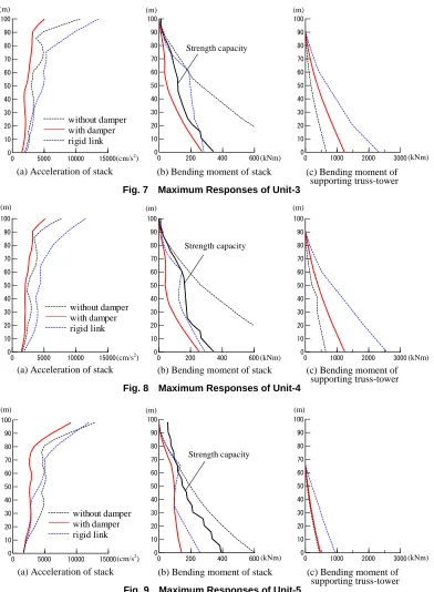
Figs. 7, 8 and 9 show the maximum response distribution of Unit-3, 4 and 5, respectively. In each figure, (a) shows the acceleration of the existing stack, (b) shows the bending moment of the existing stack, and (c) shows the bending moment of the supporting truss-tower. For comparison, each figure includes the results of the case in which the existing stack and the supporting truss-tower vibrate independently (without damper), and that in which the existing stack and the supporting truss-tower are linked by rigid springs instead of oil dampers (conventional reinforcement). Although conventional reinforcement linking the two structures with a rigid spring can reduce the bending moment of the existing stack to some extent, the responses still exceed the permissible values. In addition, the responses of the supporting truss-tower become so large that it becomes difficult to design the tower. However, with dampers, the bending moment of the existing stack meets the requirements, and the response of the supporting truss-tower is reduced to almost half of that for the rigidly linked connection in all units. In particular, the bending moment of the supporting truss-tower of Unit-5 is kept quite small compared with those of the other units, showing effect of lowering its height. Thus, the effect of structural control, which cannot be realized with conventional reinforcement, is clearly recognized from the results of simulation analyses. Here we show the maximum damper response in Table 4. Comparing these responses with the specification shown in Table 1 confirms that the adopted damper specification still reserves a margin of safety.
In addition to the above, we conducted optional calculations by changing the damper’s damping coefficient by plus or minus 20%, which represents the differences between the devices and the fluctuations caused by the temperature dependency. It is confirmed that all the response values in these optional cases also meet the requirements.
Vertical level Unit-3 Unit-4 Unit-5
FL 90.5m 12 (L) 16 (L) -
FL 80.5m 6 (L) - -
FL 60.5m 6 (M) 8 (M) 12 (L)*1
FL 40.5m 6 (M) 8 (M) 12 (M)*2
*1: FL 65.5m *2: FL 35.5m
Table 2. Damper Distribution
Fig. 6 Vibration Model for Seismic Response Analysis for Unit-4
Unit-3 Unit-4 Unit-5
Period (s) 0.582 0.537 0.558
1st
mode Damping ratio 0.109 0.116 0.224
Period (s) 0.242 0.228 0.224
2nd
mode Damping ratio 0.279 0.406 0.073
Table 3. Complex Eigenvalues for Final Setting
Free field
Existing stack
Supporting truss-tower
MDOF parallel
model
for soil por
tion
(c) Bending moment of supporting truss-tower
0 5000 10000 15000 0 10 20 30 40 50 60 70 80 90 100 without damper with damper rigid link
0 200 400 600
0 10 20 30 40 50 60 70 80 90 100
(b) Bending moment of stack (a) Acceleration of stack
(m) (m)
(kNm) (kNm)
(cm/s2
) (m)
Strength capacity
0 1000 2000 3000 0 10 20 30 40 50 60 70 80 90 100
Fig. 7 Maximum Responses of Unit-3
(m) (m)
(m)
Type Max. response deformation Max. response velocity Location
L 154mm 121cm/s Unit-3 (FL+90.5m)
M 97mm 91cm/s Unit-4 (FL+60.5m)
Table 4. Damper Response
0 1000 2000 3000 0 10 20 30 40 50 60 70 80 90 100
0 200 400 600
0 10 20 30 40 50 60 70 80 90 100
(kNm) (kNm)
(cm/s2)
Strength capacity
0 5000 10000 15000 0 10 20 30 40 50 60 70 80 90 100 without damper with damper rigid link
(c) Bending moment of supporting truss-tower (b) Bending moment of stack
(a) Acceleration of stack
Fig. 8 Maximum Responses of Unit-4
0 200 400 600
0 10 20 30 40 50 60 70 80 90 100
0 5000 10000 15000 0 10 20 30 40 50 60 70 80 90 100 without damper with damper rigid link
(m) (m)
(kNm) (kNm)
(cm/s2)
(m)
Strength capacity
0 1000 2000 3000 0 10 20 30 40 50 60 70 80 90 100
(c) Bending moment of supporting truss-tower (b) Bending moment of stack
(a) Acceleration of stack
Fig. 9 Maximum Responses of Unit-5
DEVELOPMENT OF HIGH PERFORMANCE OIL DAMPERS
Basic Composition
Because the required specifications shown in Table 1 are beyond the capability of existing products, and high durability is indispensable when considering outdoor conditions and the importance of the target structure, we employ a newly developed high-performance oil damper designed for this project. Fig. 10 outlines the inner mechanism of the oil damper and an outside view of a full-scale device. The device consists of a cylinder, a piston, a piston rod, valves, an accumulator, etc., and it uses the resistance when the oil in the cylinder passes the valve as a damping force. Both ends of the device house a ball-and-socket joint to follow a three-dimensional complicated motion during an earthquake. The accumulator is a kind of oil reserve tank that admits a change of oil volume caused by variations of temperature.
As shown in Table 1, two types of device, L-type and M-type, are adopted here. They have the same force capacity but different numbers of valves. Their lengths are about 2.4m (L-type) and 1.9m (M-type), and their weights are about 1000kg (L-type) and 750kg (M-type). To realize the required damping coefficient and velocity capacity, the L-type and the M-type devices employ six or four unit valves that can generate a linear damping force in proportion to a velocity of up to 30cm/s (Fig. 11). As mentioned before, adjusting the damper parameter by only the number of common valves can streamline the development of the device because we only have to design and test one valve.
Performance Test on Full-scale Device
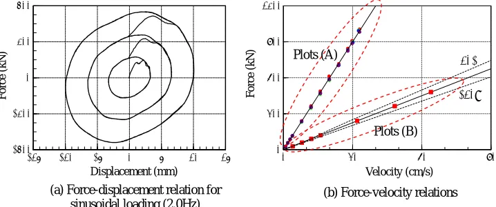
To verify the performance of the developed oil damper, we conducted dynamic loading tests on a full-scale M-type device. Because of the function attached to the valve, each valve unit can be externally controlled to be in operation or not. Fig. 12 shows typical test results. Fig. 12(a) shows a force-displacement relation for a sinusoidal loading with a frequency of 2.0Hz when only one valve unit is in operation. The oval force-displacement loops, which are associated with a linear viscous damper, are observed in accordance with the three levels of loading amplitudes. From this figure, it is also observed that this device has no mechanical gap. Fig. 12(b) shows the relations between loading velocity and generated reaction force. Plots (A) are the results when one valve unit is in operation, and the plots include the results of four different valves. Plots (B) are the results when all four valves work together. We can see the same relation as that shown in Fig. 11. The block line in Fig. 12(b) indicates the target specification, and the two dotted lines indicate plus or minus 10% of it. From Fig. 12(b), we can recognize that the difference between the valves is very small, and the highly linear characteristic, which meets the specification, is realized.
Fig. 13 displays a change of damping coefficient under various temperatures of inner oil. The results are normalized by a value of 27 degrees. Although a slight temperature dependency is observed for a small force, the percentage change is less than plus or minus 10% in the temperature range from -5 to 60 degrees. For a large force, which is important for seismic response control, the change of damping coefficient is very small. As mentioned in the former chapter, we considered a 20% fluctuation in damping coefficient in design. The test results indicate its validity when we take account of both the differences between the valves and the fluctuations due to temperature dependency.
Piston Valve Accumulator
Oil Ball-and-socket joint
Cylinder
Fig. 11 Force-velocity Relation of Oil Damper
Velocity (cm/s) 900
Force (kN)
30 180
Unit valve
120
M-type (4 units) L-type (6 units)
Fig. 10 Outline of Oil Damper
CONCLUSION
This paper has presented a seismic upgrading project introduced for an existing stack using oil dampers that will become the first full-scale application of structural control technology to an actual nuclear power station facility in Japan. We planned to build a new supporting truss-tower surrounding the existing tube-shaped stack and to link the two structures via oil dampers to augment damping ratio to the structures as well as to improve the strength. The damper parameters and allocation including the shape of the supporting truss-tower were carefully examined in considering the given conditions and the control effect. Numerical analysis results showed remarkable response reduction effects, which cannot be realized by conventional reinforcement. Because it was also clarified that the required damper specifications are beyond the capability of existing products, a high-performance oil damper has been developed for this project.
Authorization has been obtained for this upgrading project and it is now under construction. This project will be completed in 2007, and large-scale forced vibration tests are planned just before completion. We will report these test results at the earliest opportunity.
REFERENCES
1. Onouchi, A. and Tachibana, A. “Forced Vibration Test of an ABWR Nuclear Reactor Building -Simulation Analysis by MDOF Parallel Model-,” 18th International Conference on Structural Mechanics in Reactor Technology (SMiRT18), Beijing, China, August 7-12, 2005. K13-6.
-10 0 10 20 30 40 50 60 70
0.70 0.80 0.90 1.00 1.10 1.20 1.30
210kN 330kN 560kN 850kN Fig. 12 Test Results of Full-scale Device (M-type)
Fig. 13 Temperature Dependency
Displacement (mm)
F
o
rce (kN)
0 30 60 90
0 300 600 900 1200
Plots (A)
Plots (B)
+10%
-10%
Velocity (cm/s)
F
o
rce (kN)
(a) Force-displacement relation for sinusoidal loading (2.0Hz)
(b) Force-velocity relations
C
h
an
ge
of
da
m
p
in
g c
o
ef
fi
ci
en
t
(2
7
de
gree C
=
1
.0
)
Temperature (degree C)
Force level
+10%
-10%
-15 -10 -5 0 5 10 15