Performance Based Seismic Design of Braced
Composite Multi Storied Building
P.SAIRAJ 1, K.PADMANABHAM 2
M. Tech Student, Department of Civil Engineering, GVPCOE (A), Visakhapatnam, A.P., India 1
Associate Professor, Department of Civil Engineering, GVPCOE (A), Visakhapatnam, A.P., India 2
Abstract: Steel-concrete composite construction system is an efficient, economical and innovative method for seismic resistance of multi storied buildings. This paper represents a study on economic aspects of G+4 multi storied building designed by using braced frame composite construction. Since ductility, stiffness, inter storied drift and lateral displacements are the critical issues in seismic design of buildings, different types of braced frame models are developed in this study and evaluated its structural performance. Equivalent static method of seismic analysis used in the analysis of geometric models and the results are compared with STRAP software. This study makes an attempt, to develop efficient geometric models for new constructions, and to provide necessary structural configuration against retrofitting of the existing structures, constructed in earthquake prone regions.
Keywords- Composite construction, seismic zone, ductility, lateral displacement, braced model, Strap software.
I. INTRODUCTION
Composite structures are reliable and show good performance against stiffness, strength, ductility, and which are the key parameters for design of seismic resistance high raised buildings. Braced frame models are efficient means to transfer lateral forces caused by wind and earthquake. Braced frames are less weight than shear walls, so that it will attract less seismic forces. Braced frames models are proven effective means to enhance ductility of the structure and efficient means to control inter storey drift and lateral displacement of the structure.
II. OBJECTIVE OF STUDY
The objective of this study is to develop efficient building models by using combination of CBF & EBF braced frames. Five types of multi storied braced frame models are developed in seismic zone III, and evaluated its structural performance with respect to member strength, ductility and inter storey drift. Equivalent static method used for seismic analysis and the results are verified by STRAP software. The results of all five models are analyzed (Ref Table 2-5) and selected an efficient structural model for design of five storied commercial building.
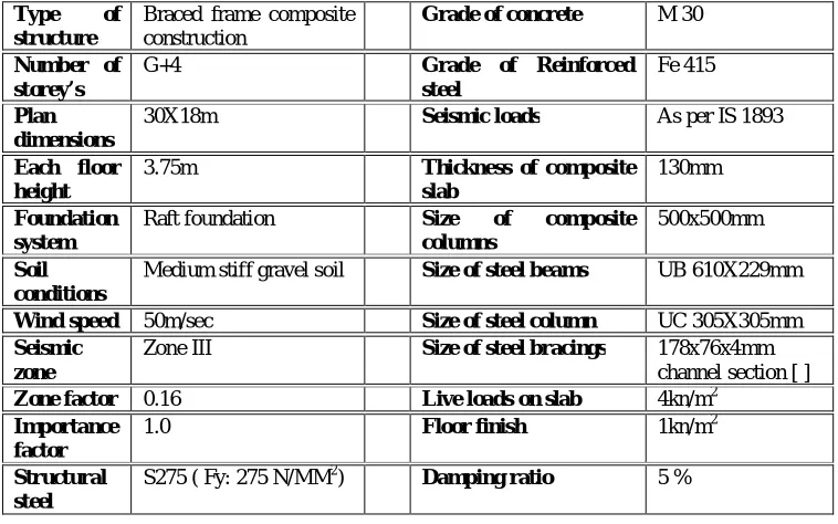
Table 1: Data for analysis of G+4 building Type of
structure
Braced frame composite construction
Grade of concrete M 30
Number of storey’s
G+4 Grade of Reinforced steel
Fe 415
Plan dimensions
30X18m Seismic loads As per IS 1893
Each floor height
3.75m Thickness of composite
slab
130mm
Foundation system
Raft foundation Size of composite
columns
500x500mm
Soil conditions
Medium stiff gravel soil Size of steel beams UB 610X229mm
Wind speed 50m/sec Size of steel column UC 305X305mm Seismic
zone
Zone III Size of steel bracings 178x76x4mm
channel section [ ] Zone factor 0.16 Live loads on slab 4kn/m2
Importance factor
1.0 Floor finish 1kn/m2
Structural steel
S275 ( Fy: 275 N/MM2) Damping ratio 5 %
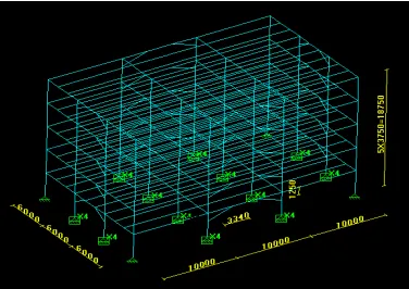
Fig 1: Shows typical floor plan and position of 16 columns represented by C1 to C16 and beams. All the column sections are made with encased steel concrete composite construction. The spacing between the columns are 6m in lateral direction [x direction] and 10m in longitudinal direction [y direction].Beams are divided in to two categories as primary and secondary beams. Primary beams are directly rest on columns with restrained end conditions. Secondary beams are those which are connected to the primary beams by semi rigid connections. Secondary beams are provided with stud type shear connectors to facilitate composite action by floor slab.
(a): Bare frame composite structure-(without bracing) (b): Knee -type concentric mid span bracing
(c): Haunch type eccentric mid span bracing (e): Chevron & X type eccentric and concentric bracing
(d) K & X type concentric end span bracing
III.ANALYSIS
Fig 2: Constitute five different types of braced frame models (a, b, c, d, and e) considered in the analysis. Model (a) is a bare frame five storied structure without bracings. Model (b) is a knee type concentric bracing arranged in the mid span of external frame in both X & Z directions. Model (c) is a haunch type eccentric bracing pattern arranged in the mid span of external frame in both X & Z directions. Model (d) is a K & X type concentric bracing pattern respectively, arranged in the end span of external frame in both X & Z directions. Model ( e) is a chevron & X type eccentric and concentric bracing pattern arranged in the end span of external frame in both X & Z directions respectively. The explained five types of building models analyzed by using Equivalent static method and the results are verified by STRAP software. Design parameters such as support reactions, bending moment, shear force, overall deflection, and story drift are verified as per the values presented in Table 3, 4, 5 & 6.
IV. RESULTS
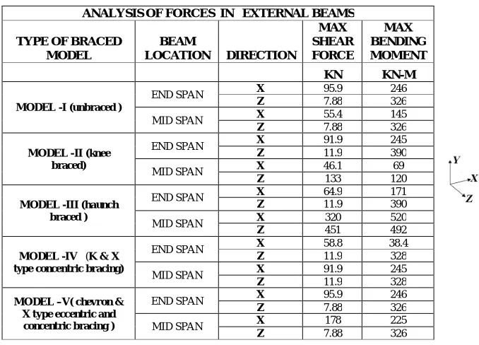
Table 2 Maximum moments and forces in External Beams of five different models
Table 2, Represents the Analysis of forces in external beams for five different braced composite models, the forces which are maximum shear forces and maximum bending moments of end span and mid span of External Beams.
ANALYSIS OF FORCES IN EXTERNAL BEAMS
TYPE OF BRACED MODEL
BEAM
LOCATION DIRECTION
MAX SHEAR FORCE
MAX BENDING MOMENT
KN KN-M
MODEL -I (unbraced )
END SPAN X 95.9 246
Z 7.88 326
MID SPAN X 55.4 145
Z 7.88 326
MODEL -II (knee braced)
END SPAN X 91.9 245
Z 11.9 390
MID SPAN X 46.1 69
Z 133 120
MODEL -III (haunch braced )
END SPAN X 64.9 171
Z 11.9 390
MID SPAN X 320 520
Z 451 492
MODEL -IV (K & X type concentric bracing)
END SPAN X 58.8 38.4
Z 11.9 328
MID SPAN X 91.9 245
Z 11.9 328
MODEL –V( chevron & X type eccentric and concentric bracing )
END SPAN X 95.9 246
Z 7.88 326
MID SPAN X 178 225
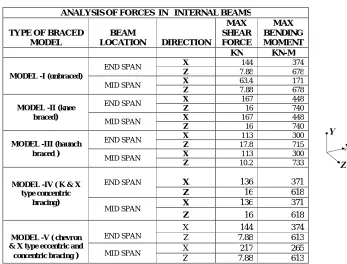
Table 3 Maximum moments and forces in internal beams of five different models
Table 4 Maximum Support Reactions for internal columns C6, C7, C10, and C11 of five different models ANALYSIS OF FORCES IN INTERNAL BEAMS
TYPE OF BRACED MODEL
BEAM
LOCATION DIRECTION
MAX SHEAR FORCE MAX BENDING MOMENT
KN KN-M
MODEL -I (unbraced)
END SPAN X 144 374
Z 7.88 678
MID SPAN X 63.4 171
Z 7.88 678
MODEL -II (knee braced)
END SPAN X 167 448
Z 16 740
MID SPAN X 167 448
Z 16 740
MODEL -III (haunch braced )
END SPAN X 113 300
Z 17.8 715
MID SPAN X 113 300
Z 10.2 733
MODEL -IV ( K & X type concentric
bracing)
END SPAN X 136 371
Z 16 618
MID SPAN X 136 371
Z 16 618
MODEL -V ( chevron & X type eccentric and concentric bracing )
END SPAN
X 144 374
Z 7.88 613
MID SPAN X 217 265
Z 7.88 613
COLUMNS FX FY FZ MX
KN KN KN KN-M
MODEL -I (unbraced)
C6 219 4656 96.2 1010
C7 219 4656 95.8 1010
C10 219 4656 96.2 1010
C11 219 4656 95.8 1010
MODEL -II (knee braced)
C6 6.9 4622 57.6 249
C7 6.9 4622 57.6 249
C10 6.9 4622 57.6 249
C11 6.9 4622 57.6 249
MODEL -III (haunch braced )
C6 27.2 5677 82.4 388
C7 27.2 5677 82.1 386
C10 27.2 5677 80.1 386
C11 27.2 5677 79.8 385
MODEL -IV ( K & X type concentric
bracing)
C6 1.7 4622 29.6 88.1
C7 1.7 4622 29.6 88.1
C10 1.7 4622 29.6 88.1
C11 1.7 4622 29.6 88.1
MODEL -V ( chevron & X type eccentric and concentric bracing )
C6 255 4661 242 76.6
C7 255 4661 242 76.6
C10 255 4662 242 76.6
Table 3, Represents the Analysis of forces in internal beams for five different braced composite models, in which maximum shear forces and maximum bending moments of end span and mid span Internal Beams. In model -V (chevron & X type eccentric and concentric bracing) which shows the lesser values than any other models and all sections are safe under Lateral loads and Gravity Loads. Table 4 Represents the Internal Column support reactions, Forces along X, Y, Z directions, which shows FX, FY, FZ and Moments along X-direction, which shows MX are presented.
Table 5 Maximum Support Reactions for External Columns C1, C2, C3, C9, C13, and C14and C15 of five different models
EXTERNAL COLUMN SUPPORT REACTIONS
MODELS COLUMNS FX FY FZ MX MZ
KN KN KN KN-M KN-M
MODEL -I (unbraced)
C1 937 1363 115 1023 3509
C2 220 2659 134 1035
C3 220 2562 134 1035
C9 219 2448 96.5 1010
C13 935 1363 115 1023 3598
C14 218 2562 134 1035
C15 218 2521 134 1035
MODEL -II (knee braced)
C1 194 1363 77.2 261 603
C2 226 2759 96.9 274
C3 226 2759 96.9 274
C9 16.8 3237 455 602
C13 194 1363 77.2 261 603
C14 226 2759 96.9 274
C15 226 2759 96.9 274
MODEL -III (haunch braced)
C1 413 1696 99 397 1231
C2 161 3243 113 402
C3 161 3243 108 496
C9 80.5 3802 375 710
C13 413 1696 104 404 1231
C14 161 3243 132 426
C15 161 3243 132 425
MODEL -IV ( K & X type concentric bracing)
C1 312 2032 256 100 117
C2 274 2533 66.8 113
C3 274 2533 66.9 113
C9 16.2 2576 242 87.9
C13 312 2123 311 100 117
C14 274 2533 66.8 113
C15 274 2533 66.9 113
MODEL -V ( chevron & X type eccentric and concentric bracing )
C1 79.4 1363 49.6 78.8 178
C2 208 2577 69.2 91.1
C3 208 2578 69.2 91.1
C9 21.2 2471 216 76.6
C13 79.5 1363 49.6 78.8 178
C14 209 2577 69.2 91.1
Table 5 Represents the External Column support reactions, Forces along X, Y, Z directions, which shows FX, FY, FZ and Moments along X, Z-direction, which shows MX and MZ are presented. During Analysis all external Column sections are failed except in model 5, because of combination of Eccentric and Concentric bracings are used in modeling of structure in model-5.
(a) (b)
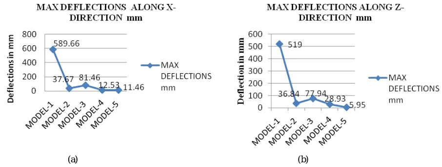
Fig 3: (a) represents the maximum overall deflection of a building along x-direction, (b) represents the maximum overall deflection of a building along z- direction. From the above figures we can observe that maximum deflection of model-5 (chevron & X type eccentric and concentric bracing) is Less than other models. Hence Model -5 is proposed for design of composite multi storied building.
Fig 4: Storey Drift for Model-5 along X & Z direction
V. RESULTS AND DISCUSSIONS
1. Considering overall deflection of the structure, (X & Z directions), bending moments, shear forces in beams and column, model IV is selected from the five trail models.
2. In model – 4, The Lateral Load Resistance System provided by arrangement of Eccentric braced frames (as shown in figure) in both external and internal mid spans (X direction) and Concentric X type braced frames in mid span in both external and internal mid spans ( Z direction.)
3. Due to the truss action formed in the braced frame model, the design may concentrate distribution of seismic lateral loads by bracings and both external, internal walls are exempted to transfer shear loads by other structural members. This consideration helps to avoid soft storey failure in seismic multi storied buildings. 4. Maximum lateral deflections of G+4 multi storied building is limited to X direction 8.5 mm (long span of
building) and Z direction 5.95mm( Short span direction of the building)
5. The Maximum inter storey drift between the floors are limited to 1.8mm (X direction) and 1.5mm(Direction), which are less than allowable tolerance limits in buildings.
VI. CONCLUSIONS
1.
Braced frame models are efficient means to show ductile performance of the structure, and they provide effective means of lateral load resistance system.2.
The overall displacement and inter storey drift of the structure can effectively controlled by adopting braced frame models.3. The designer has versatility to adopt different patterns of braced frames for lateral load resisting system. 4. Braced frames are light weight structure with good strength and stiffness .Due to this reason; these models are
less susceptible against seismic forces acting on the structure.
5. Braced composite construction is an effective measure for construction of earth quake resistant multi storied buildings due to the fact that both structural and material performance shows efficient considerations to control seismic forces.
6. Soft storey effect can effectively controlled by braced frame action .This concept is very useful for retrofitting of, and seismic up gradation of the existing multi storied buildings.
REFERENCES
[1]D. R. Panchal and P.M.Marathe , “Comparative Study of R.C.C, Steel and Composite (G+30 Storey) Building”, Institute of Technology Nirma University, Ahmedabad-382 481, 08-10 December, (2011).
[2] Sayed Hammed Hashemi ,” Ductility and Ultimate Strength of Eccentric Braced Frame”, International Conference on Advanced Materials Engineering IPCSIT vol.15 , Singapore (2011).
[3] Egor p .popov & Micheal D.Engelhardt , “ Seismic Eccentrically Braced Frames” , J .Construct Steel Research 10 , 321-354 ,US (1988).
[4] Rafeel Sabelli ,Charles w.Roeder , Jerome F.Hajjar ,” Seismic Design of Steel Special Concentrically Braced Frame System” NEHRP technical note of NIST , US , July (2013).
[5] S. Elnashai, “Seismic Resistance of Composite Beam-Columns in Multi-Storey Structures” , J. Construct. Steel Research 30 Elsevier Science Limited. (1994).
[7] Shosuke Morino, Keigo Tsuda“Design and Construction of Concrete-Filled Steel Tube Column System in Japan” published in Earthquake Engineering and Engineering Seismology, Vol. 4, No. 1 .(2012).
[8] R.P. Johnson , Professor of civil engineering, University of Warwick “Composite Structures of Steel- Concrete Composite Construction”, Volume-1, Second Edition.
[9] BS 4-1 1993,Member capacities of steel sections, Steel construction Institute.
[10] BS 5950-1 2000, Structural use of steelwork in building —Part 1: Code of practice for design of Rolled and welded sections. BSI. [11] BS 5950 (Part 3) 2000,Design in Composite Construction, British Standards Institution, London.
[12] IS: 875(part 1) –1987), handbook on code of practice for design loads (other than earthquake) for buildings and structures (bureau of
indian standards, new delhi, 1989.
[13] IS: 875(Part 2) –1987), Handbook on Code of Practice for Design Loads (Other than Earthquake) for Buildings and Structures Bureau of Indian Standards, New Delhi, 1989.
[14] (IS: 875(Part 3) –1987), Handbook on Code of Practice for Design Loads (Other than Earthquake) for Buildings and Structures Bureau of Indian Standards, New Delhi, 1989.
[15] (IS: 1893(Part 1) – 2002),Handbook on Criteria for Earthquake Resistant Design of Structures Bureau of Indian Standards, New Delhi,
1989.
BIOGRAPHY
Mr. P.SAI RAJ is an M. Tech Scholar at GVP College of Engineering, Visakhapatnam. His areas of interest are Design of RCC, Steel and Composite structures. His mail-id is [email protected]
Mr. K Padmanbahm is working as Associate Professor in the department of Civil Engineering at GVP College done M.E (Structures) , MBA ,B.E,DCM ,DSE. He has 22 years of Industrial experience with various multinational companies in Middle East countries. His areas of interests are design of Steel, RCC and composite structures. He is actively involved to provide design and execution services for Industrial structures, off shore constructions, and Bridges. He is a Charted Engineer and obtained life membership from Institute of Engineers (India), Institute of Bridge Engineers(India), Institute of Values (India),Institute of Fire and Safety(India).His email id [email protected]