ISSN: 2319-8753
International Journal of Innovative Research in Science,
Engineering and Technology
(An ISO 3297: 2007 Certified Organization)
Vol. 3, Issue 11, November 2014
Effectiveness Improvement of Shell and Tube
Type Heat Exchanger
Kirtan Gohel
Department of Mechanical Engineering, Narnarayan Shastri Institute of Technology, Ahmedabad, Gujarat, India
ABSTRACT: Generally, 35-40% of the heat exchangers used in industries are shell and tube heat exchanger. Here an experiment on shell and tube type heat exchanger is conducted. There are problems like scaling, fouling, welding defects and maintenance cost. In this experiment, design of shell and tube type heat exchanger baffle is changed. Considering this design as the basis, effectiveness of shell and tube type heat exchanger is measured. Performance in terms of effectiveness is firstly measured for normal flat baffle having 3:2 cutting ratio. Then performance in terms of effectiveness is measured for helical baffle. After measuring the performance for both types of baffle, results of both experiments are compared. Also the turbulence gained due to helical baffle helps to reduce the fouling effect in the heat exchanger.
KEY WORDS: Effectiveness, Helical Baffle, Heat Transfer rate, Turbulance.
I. INTRODUCTION
In this type of heat exchanger one of the fluids flows through a bundle of tubes enclosed by a shell. The other fluid is forced through the shell and it flows over the outside surface of the tubes. Such an arrangement is employed where reliability and heat transfer effectiveness are important.
ISSN: 2319-8753
International Journal of Innovative Research in Science,
Engineering and Technology
(An ISO 3297: 2007 Certified Organization)
Vol. 3, Issue 11, November 2014
II. CONSTRUCTION AND WORKING OF HEAT EXCHANGER AS PER DESIGN
As per dimensions a model of shell and tube type heat exchanger was fabricated. The fabricated model of shell and tube type heat exchanger is shown in the below figure.
FIG: Model of shell and tube type heat exchanger
Serial No. Parameter Dimension
1 Shell O.D. 90 mm
2 Shell I.D. 84 mm
3 Diameter of Tube
holes
17 mm
4 Tube thickness 3 mm
5 No of tubes 7
6 Material of Tube Copper
Table: Dimensions of shell and tube heat exchanger
III. CONSTRUCTION AS PER DESIGN
The heads are at the either side of the shell as shown in the figure assembly. Tube sheet is provided in between the shell and head in order to prevent leakage of either fluids and mixing of each other. It is having 7 holes for supporting the copper tubes and 8 holes for bolting. Copper tubes are enclosed inside the shell having inner diameter 84 mm and thickness 6 mm. The inner diameter and thickness of copper tubes are 13.9 mm and 1.5 mm respectively. One baffle is provided at one side of the center of the tube and another baffle is provided at the another side of the tube center at same distance (44 mm). The head, tube sheet and shell are connected with the help of bolt at both the sides. Champion sheet is provided for preventing the leakage of fluid between head and tube sheet as well as between tube sheet and shell.
ISSN: 2319-8753
International Journal of Innovative Research in Science,
Engineering and Technology
(An ISO 3297: 2007 Certified Organization)
Vol. 3, Issue 11, November 2014
FIG: Helical baffle
IV. WORKING AS PER DESIGN
In this shell and tube type heat exchanger, both the fluids flow in opposite directions. The hot and cold fluids(water) enter at the opposite ends. The temperature difference between the two fluids remains more or less nearly constant. This type of heat exchanger, due to counter flow, gives maximum rate of heat transfer for a given surface area. Hence such heat exchangers are most favored for heating and cooling of fluids.
The hot fluid enters at a temperature of th1 through the inlet head and after that it passes through the copper tubes which is having higher thermal conductivity. Because of higher thermal conductivity the heat transfer will occur effectively. After that the hot fluid having reduced temperature passes through the outlet head and exit the heat exchanger with temperature th2.
Cold fluid enters into the shell with temperature tc1 and it flows surrounding the copper tube inside the shell. Due to heat transfer between hot fluid and clod fluid the temperature of cold fluid gradually increases and after that the cold fluid exit the heat exchanger through the other side of the shell with a temperature of tc2.
V. METHODOLOGY
ISSN: 2319-8753
International Journal of Innovative Research in Science,
Engineering and Technology
(An ISO 3297: 2007 Certified Organization)
Vol. 3, Issue 11, November 2014
VI. OBSERVATION TABLE
No.
Temperature For Flat Baffle (˚C)
Temperature For Helical Baffle (˚C)
Th1 Tc1 Th2 Tc2 Th1 Tc1 Th2 Tc2
1 44 15 42 18.2 44 15 40.8 20.1
2 46 15 43 19.8 46 15 41.7 21.84
3 51 15 47 21.4 51 15 44.9 24.7
4 60 15 54 24.5 60 15 50.5 30.11
5 65 15 57.6 26.8 65 15 54 32.5
Table: Observation Table
Various calculations are done as per following procedure. • Calculate Heat Transfer Rate (Q , kJ/s) :-
Q = m Cp (Th1 – Th2) = m Cp (Tc2 – Tc1)
Where, m = mass flow rate, kg/s
Cp = specific heat of fluid at constant pressure, J/ kg ˚C Th1 = inlet temperature of hot fluid, ˚C
Th2 = outlet temperature of hot fluid, ˚C Tc1 = inlet temperature of cold fluid, ˚C Tc2 = outlet temperature of cold fluid, ˚C
• Logarithmic Mean Temperature Difference (LMTD) :- θm = (θ1 - θ2) / ln(θ1/ θ2)
Where, θ1 = (Th1 – Th2), θ2 =(Tc2 – Tc1)
Area of heat transfer (A, m2) :-
A = n*2πrl
Where, n = Number of tubes, r = Radius of tube, l = Length of tube
• Overall heat transfer coefficient (U, W/m2 ˚C) :- U = Q / A θm
• Effectiveness ( ε) :-
ISSN: 2319-8753
International Journal of Innovative Research in Science,
Engineering and Technology
(An ISO 3297: 2007 Certified Organization)
Vol. 3, Issue 11, November 2014
Where, Ch= mhCph, Cc = mcCpc,
Cmin=minimum of Ch and Cc,
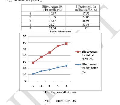
Effectiveness for Flat Baffle (%)
Effectiveness for Helical Baffle (%)
1 10.97 17.55
2 15.39 22.06
3 17.67 26.95
4 21.21 33.58
5 23.54 35
Table : Effectiveness
FIG: Diagram of effectiveness
VII. CONCLUSION
After performing an experiment, results of both baffles are compared. So, it is concluded that effectiveness of helical baffle is high compared to flat baffle for same inlet temperature of hot water and cold water.
REFERENCES
1. M. M. El-Fawal, A. A. Fahmy and B. M. Taher, “Modelling of Economical Design of Shell and tube heat exchanger Using Specified Pressure Drop”, Journal of American Science.
2. Rajeev Mukharji, “Effective design of shell and tube heat exchanger”, American Institute of Chemical Engineering, 1988. 3. www.hcheattransfer.com
4. Heat and Mass Transfer by R.K.Rajput in S.CHAND Publication.
0 10 20 30 40 50 60 70
1 2 3 4 5
Effectiveness for Helical Baffle (%)