A th esis su b m itted for d egree o f D o cto r o f P h ilo so p h y
in C hem ical E n gin eerin g
D arren G obby
UCL
All rights reserved
INFORMATION TO ALL USERS
The quality of this reproduction is dependent upon the quality of the copy submitted.
In the unlikely event that the author did not send a complete manuscript and there are missing pages, these will be noted. Also, if material had to be removed,
a note will indicate the deletion.
uest.
ProQuest U643956
Published by ProQuest LLC(2016). Copyright of the Dissertation is held by the Author.
All rights reserved.
This work is protected against unauthorized copying under Title 17, United States Code. Microform Edition © ProQuest LLC.
ProQuest LLC
789 East Eisenhower Parkway P.O. Box 1346
I wish to express my thanks to my supervisors Dr. A sterios G avriilidis and Prof. D avid Bogle for their advice, guidance and su p p o rt during th e course of this study.
I would also like to th an k Dr. P an ag io ta Angeli, Dr. Ian Eames and Dr. Eric Fraga.
I would like to th an k my family and friends for th eir su p p o rt and encouragement.
T he dem and for safer and more efficient chemical plants has lead the reaction engineer to consider new technologies. Process intensification steers partially to wards this goal by the reduction of large inventories. M icroreaction technology can be seen to be a lim it of process intensification, by perform ing u n it operations in sub m m sized domains. High specific interfacial areas and well a defined hydrodynam ic environm ent allow precise control of an intrinsically safe operation. M icroreaction technology is still an emerging discipline and a thorough u n derstanding of th e im p o rta n t design and operating param eters are needed to gain ind u strial acceptance.
The aim of this work is to understand the tra n sp o rt characteristics of energy and mass a t this scale, in a theoretical m anner, to provide th e reaction engineer w ith some m odelling tools th a t allow conceptual insight into th e m icroreactor design. In addition the understanding of tra n sp o rt phenom ena a t th is scale is applied to some un it operations allowing the dom inant design and o p eratin g param eters to be identified. A nalytical and num erical sim ulations have been used and it is shown th a t the m icroreactor is insensitive to the ID velocity profile iî R > Pe > 1 for linear and non-linear kinetics in any duct shape. Highly non-isotherm al system s were shown to become near isotherm al as the conductivity in the reactor wall increased, i.e. acting as a therm al shunt.
M ultiphase systems were also investigated where it is shown analytically th a t the effect of interface curvature on reactor perform ance is negligible and transverse distance to the catalyst is th e dom inating design param eter. Two m ultiphase reac tors were considered w ith different flow profiles and under some operating conditions they are shown to have equivalent perform ance.
1 In trod u ction 14
2 L iterature Survey 17
2.1 I n tr o d u c tio n ... 17
2.2 Origins and fa b r ic a tio n ... 17
2.2.1 Photolithography and e t c h i n g ... 18
2.2.2 Chemical vapour d e p o s i t i o n ...18
2.2.3 Laser m a c h in in g ... 19
2.2.4 Electrodischarge m achining ... 19
2.2.5 Glass m ic ro fa b ric a tio n ...19
2.3 M icrofluidics... 19
2.4 M o d e ll in g ...23
2.5 A p p lic a tio n s ... 24
2.5.1 U nit o p e r a t io n s ...24
2.5.2 New operating conditions ...25
2.5.3 Process d e v e lo p m e n t...26
2.5.4 Process in te n s if ic a tio n ...26
2.6 Com parison w ith conventional catalytic r e a c t o r s ... 27
2.6.1 Gas-solid r e a c to r s ... 28
2.6.2 M ultiphase r e a c to r s ... 30
2.6.3 M ic r o re a c to rs ... 40
2.7 C o n c lu s io n s ... 45
3 M od ellin g o f M ass Transfer in M icroreactors 47 3.1 I n tr o d u c tio n ... 47
3.2 Vertically-averaged description: single first order r e a c t i o n ... 50
3.2.1 Physical description and defining e q u a tio n s ... 50
3.2.2 Vertically-averaged s o l u t i o n ... 52
3.2.3 Entrance length co n sid eratio n s... 58
3.3 F irst order parallel r e a c tio n s ... 59
3.4 F irst order series r e a c t i o n s ...61
3.5 Extension to second order reactions for sm all D am kohler num bers . . 66
3.5.1 Second order parallel re a c tio n s ... 67
3.5.2 Second order series re a c tio n s ...69
3.6 Extension to arb itrary shaped d u c t s ... 71
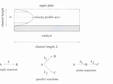
4.2 Single channel reactor ...80
4.3 Coupled plate r e a c to r ...82
4.3.1 R eactor configuration and m odel ... 83
4.3.2 2D model form ulation ... 83
4.3.3 Dimensional form of m o d e l...84
4.3.4 Dimensionless form of m o d e l... 86
4.3.5 Sum m ary of dimensionless forms ... 88
4.3.6 R eaction s y s t e m s ... 89
4.4 Results and discussion for the coupled p late r e a c t o r ... 90
4.4.1 F irst order r e a c t i o n s ...90
4.4.2 D ehydrogenation/ com bustion r e a c tio n s ...94
4.5 C o n c lu s io n s ...102
M ixin g C haracteristics o f T -ty p e M icrofluidic M ixers 105 5.1 I n tr o d u c tio n ... 105
5.2 T h e o r y ... 106
5.2.1 M athem atical model of the T r e a c t o r ... 106
5.2.2 Mixing characteristics ... 107
5.3 Results and d i s c u s s io n ... 109
5.3.1 Base c a s e ...109
5.3.2 Fluid velocity v a r ia tio n ... 109
5.3.3 Aspect ratio variation - constant w i d t h ...110
5.3.4 Aspect ratio variation - constant hydraulic d ia m e te r ... 112
5.3.5 Mixing angle v a r i a t i o n ... 113
5.3.6 T h ro ttle T m i x e r ... 115
5.4 Fourier num ber c o n s id e ra tio n s ...118
5.5 C o n c lu s io n s ... 119
C a ta ly tic M eth an ol O xid ation 122 6.1 In tr o d u c tio n ... 122
6.2 Physical d e sc rip tio n ...123
6.3 Verification of FORTRAN kinetics m o d e l... 123
6.3.1 M onolith m o d e l ...125
6.3.2 Com parison of m o d e l s ... 128
6.4 V alidation of m ethanol oxidation k in e tic s ... 128
6.4.1 M ethanol - rich oxidation ...129
6.4.2 V alidation of reaction k i n e t i c s ...132
6.4.3 Solution m ethod ... 135
6.4.4 Sum m ary of v a li d a ti o n ... 135
6.5 FDV M o d e l ... 135
6.5.1 Mass e q u a t i o n s ...135
6.5.2 Energy e q u a tio n ...137
6.5.3 Physical p r o p e r t i e s ... 141
6.5.4 Solution m ethod ... 143
6.6.3 N on-reacting f l o w ...147
6.6.4 Base case s im u la tio n s ... 150
6.6.5 O perating param eter c o n sid e ra tio n s ... 153
6 .6.6 Design param eter c o n sid e ra tio n s... 160
6.7 C o n c lu s io n s ... 172
7 M u ltip h a se M icroreactors 176 7.1 I n tr o d u c tio n ...176
7.2 N itrobenzene r e d u c tio n ...177
7.3 H orizontal porous contact m icroreactor (H P C M )...178
7.3.1 Dim ensional m o d e l ... 178
7.4 Micro falling film reactor ( M F F R ) ...179
7.4.1 Dimensionless m o d e l ... 181
7.4.2 Interface c u r v a t u r e ... 183
7.4.3 A nalytical solution a t low f lu x e s ... 183
7.4.4 Numerical m o d e l lin g ... 186
7.5 H PCM and M F F R r e s u l t s ... 186
7.6 C o n c lu s io n s ...191
8 C on clu sion s 193 8.1 M ain contributions of this t h e s i s ... 193
8.2 Suggestions for further w o r k ...195
A F O R T R A N 77 C odes 206 A .l C alculation of decay r a t e ... 206
A .2 C alculation of transverse p ro files...208
A 3 Full num erical s im u la tio n ... 211
A .4 V ertically averaged s y s t e m ...215
A .5 Vertically averaged system (flow profile) ...218
B D eriv a tio n o f D im en sion less E n ergy B ou n d ary C on d ition 222 C C F D G overning E quations 224 D P E R V erification P aram eters 225 E F O R T R A N 90 C odes 226 F F O R T R A N 90 C odes 231 F .l n rty p e .fO O ... 232
F.2 driver.fOO ... 233
F.3 solvers.f90 ... 236
F.4 transfer.f90 ... 261
F.5 gm ressolver.fO O ... 264
2.1 M ulti-tube plug flow re a cto r... 29
2.2 Schematic of a bubble column slurry re a cto r...33
2.3 Schematic of je t loop reacto r... 35
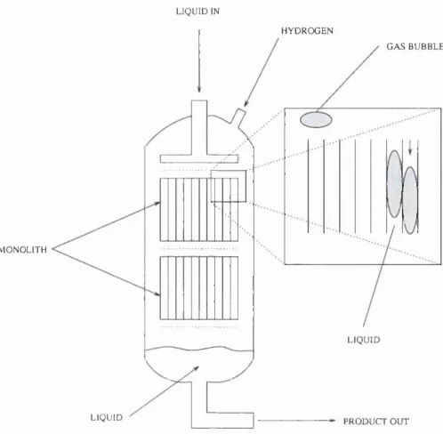
2.4 Schematic of a m onolith re acto r... 37
2.5 Schematic of slurry re a cto r... 38
2.6 Dimensionless RTD for various tu b e d iam eters...44
2.7 Dimensionless RTD for mixed flow conditions...44
3.1 Schematic of isotherm al plate m icroreactor... 49
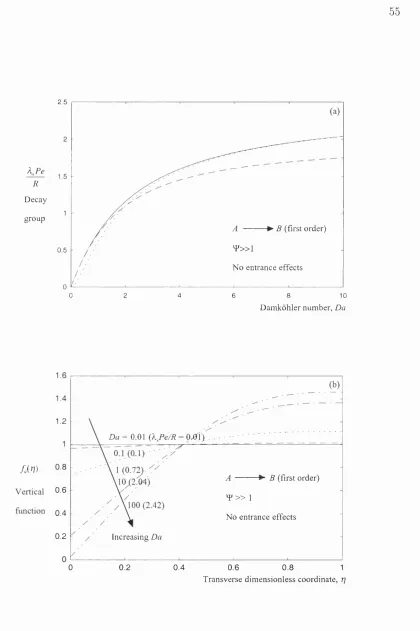
3.2 Decay groups and vertical function profiles of com ponent A ... 55
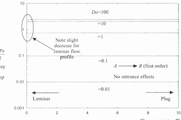
3.3 V ariation of th e decay group w ith ^ for different Da num bers...57
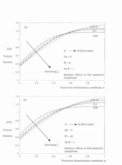
3.4 Vertical function profiles of reactan t A at th ree positions dow nstream from the in let... 60
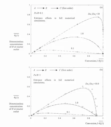
3.5 O utlet reactor concentration of series interm ediate B as a function of conversion...65
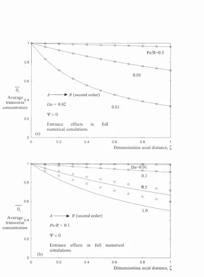
3.6 Axial concentration profiles for a second order reactio n... 68
3.7 Axial concentration profiles for parallel reactio n s... 70
3.8 O u tlet reactor concentration of series in term ed iate B as a function of conversion (second order system s)... 72
3.9 C ircular duct decay constant for reactan t A as a function of Da. . . . 75
4.1 Dimensionless axial reactan t profiles for different D am kohler and (3 num bers... 82
4.2 Schematic of coupled plate re acto r...83
4.3 P lot of conversion and tem p eratu re vs dimensionless axial length for first order base case... 92
4.4 Axial tem peratu re profiles for varying ^2 n u m b ers... 93
4.5 Axial tem peratu re profiles for varying Da2 num bers...94
4.6 Conversion in channels 1 and 2 and te m p e ratu re profiles for dehydro genation / combustion base case... 96
4.7 T em perature profiles for varying Dai num bers... 97
4.8 Conversion in channel 1 and tem p eratu res for varying Pe numbers. . 98
4.9 Axial tem p eratu re profiles a t different radial p o sition s...99
4.10 Axial tem p eratu re profiles for varying channel size...100
4.11 Conversion profiles in channels 1 and 2 for varying channel size. . . . 101
5.1 Schematic of T m ixer... 108
5.5 Velocity m agnitude contours in a 0.1 aspect ratio m ixer...112 5.6 Mixing length vs aspect ratio for d = 375 m icrons... 113 5.7 Velocity m agnitude contours in a m ixer w ith a 45® m ixing angle and
0.3 m /s inlet velocities...114 5.8 Velocity m agnitude contours in a m ixer w ith a -45® m ixing angle and
0.3 m /s inlet velocities...114 5.9 M ethanol mass fraction contours in a 160 m icron th ro ttle a t inlet
velocities of 0.3 m /s ... 115 5.10 Mixing length vs th ro ttle size (m icrons)...117 5.11 Mixing length vs fluid velocity a t inlet channels (10 m icron th ro ttle). 117 5.12 M ethanol mass fraction contours a 10 m icron th ro ttle mixer a t inlet
velocities of 5 m /s ...118 6.1 Image of the m ethanol oxidation m icroreactor... 124 6.2 End elevation of the reacting channel (not to scale)...124 6.3 Com parison of wall tem p eratu re profiles for cataly tic combustion. . . 129 6.4 Schematic of the solution dom ain for th e m ethanol oxidation reactor
(not to scale)... 136 6.5 Com parison of FDV and P E R m odels... 146 6.6 Com parison of reactan t profiles (isotherm al o p eratio n )...147 6.7 Average axial tem p eratu re profiles for different solid thickness scaling
factors for Peg of 30.0 and P e ^ of 50.0... 149 6.8 Average axial tem p eratu re profiles for different power densities for
Pcg of 30.0 and P e ^ of 50.0, other param eters are set according to Table 6.8...149 6.9 Average axial dimensionless tem p eratu re profiles for different flowrates
(factors of base Peclet num ber) w ith no heater power, other param e ters are set according to Table 6.8... 150 6.10 Average axial dimensionless tem p eratu re profiles for different flowrates
(factors of base Peclet num ber) w ith a power density of 7.5 x 10® W /m ^.l5 1 6.11 Average, catalytic and to p wall axial dimensionless te m p eratu re pro
file in th e m ethanol oxidation m icroreactor for base case param eters. . 152 6.12 Average axial mass fraction profiles for m ethanol, oxygen and formalde
hyde in th e m ethanol oxidation m icroreactor for base case param eters. 152 6.13 Average axial m ethanol mass fraction profiles in the m ethanol oxida
tion m icroreactor for different flow rates...154 6.14 Average axial dimensionless tem p eratu re profiles in th e m ethanol ox
idation m icroreactor for different flow rates...154 6.15 Axial dimensionless tem p eratu re profiles a t th e cataly st in th e m ethanol
oxidation m icroreactor for different flow rates...155 6.16 Average and cataly st axial dim ensional tem p eratu re profiles for dif
ferent inlet tem p eratu res...156 6.17 Average axial m ethanol mass fraction profiles for different inlet tem
6.18 Average axial dimensionless tem p eratu re profiles for different inlet
com positions and power densities...158
6.19 Average axial mass fraction profiles of m ethanol for different inlet com positions and power densities...158
6.20 Average axial mass fraction profiles of form aldehyde for different inlet com positions and power densities...159
6.21 Average axial m ethanol mass fraction profiles for different channel heights...162
6.22 Average axial formaldehyde mass fraction profiles for different channel heights...163
6.23 C atalytic axial m ethanol mass fraction profiles for channel heights between 300 and 390 m icrons... 163
6.24 C atalytic axial m ethanol mass fraction profiles for different channel heights...164
6.25 Average axial dimensionless tem p eratu re profiles for different channel heights...165
6.26 C atalytic axial dimensionless tem p erature profiles for different chan nel heights...165
6.27 Transverse m ethanol mass fraction profiles a t different dimensionless axial distances for a channel height of 300 m icrons (base case)...166
6.28 Transverse m ethanol mass fraction profiles for different dimensionless axial distances for a channel height of 750 m icrons... 166
6.29 Transverse m ethanol mass fraction profiles for different dimensionless axial distances for a channel height of 1100 m icrons... 167
6.30 Average axial mass fraction profiles for m ethanol, oxygen and formalde hyde for a channel height of 2000 m icrons... 168
6.31 Average axial mass fraction profiles for w ater, hydrogen and carbon dioxide for a channel height of 2000 m icrons... 168
6.32 Average axial mass fraction profiles for m ethanol, oxygen and formalde hyde for a channel height of 2000 microns w ith fixed te m p eratu re wall boundary conditions [9 = 1.27)...169
6.33 Average axial tem p eratu re profile for a channel height of 2000 microns w ith fixed tem p eratu re wall boundary conditions [9 = 1.27)... 169
6.34 Average axial dimensionless tem p eratu re profiles for different solid heights...171
6.35 Average axial m ethanol mass fraction profiles for different solid heights. 171 6.36 Average axial formaldehyde mass fraction profiles for different solid heights...172
7.1 Schematic of th e H PC M ... 178
7.2 Schematic of M F F R stru c tu re ...180
7.3 C oordinate directions in the M F F R ... 181
7.6 Mass fraction profile of aniline for a reaction m ixture velocity of 1 x
10“ ^ m /s (not to scale)...188
7.7 Effect of channel height on conversion... 188
7.8 Effect of reaction m ixture velocity on conversion...188
7.9 Effect of the diffusivity on conversion...189
2.1 Perform ance characteristics of gas-solid reacto rs... 30
2.2 N um erical d a ta for industrial fixed bed reacto rs...32
2.3 T ran sp o rt param eters for the CDC and C S T R ... 34
2.4 Surface characteristics of some reactor ty p e s... 41
2.5 Dimensionless bounds for 50 and 300 m icron tu b e s ...44
2.6 M erits of each type of reacto r... 46
2.7 Q u an titative m erits of each type of re a cto r...46
2.8 Q u an titative m erits of each type of re a cto r...46
2.9 Bounds of characteristic bubble sizes and void fraction for some types of re acto r... 46
3.1 Studies for single reactions in regular geom etries... 48
3.2 Studies for single reactions w ith axial diffusion in regular geometries. 48 3.3 Studies for m ultiple reactions in regular geom etries... 48
3.4 Sum m ary of analytical results describing first and second order single, parallel and series reactions occuring in a parallel p late reactor. . . . 67
4.1 Dimensionless param eters used for first order reaction system ...91
4.2 Dimensionless param eters used for th e dehydrogenation/ com bustion system ... 95
5.1 Sim ulation results for different m ixing angles...113
5.2 C om parison of 2D and 3D sim ulations for a 160 m icron th ro ttle. . . . 116
6.1 C haracteristics of 7 -AI2O 3 w ashcoat...127
6.2 O perating and geometric param eters used in calculations... 128
6.3 Values of /cq and at different tem p eratu res and activation energies. 131 6.4 Stoichiom etric table of m ethanol oxidation reactio n ...133
6.5 Mean specific heats of reacting species a t 680 K ... 134
6.6 R esults from adiabatic P F R program ... 134
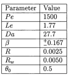
6.7 C om parison of industrial param eters w ith ad iab atic P F R param eters. 135 6.8 Design param eters of the m ethanol oxidation m icroreactor... 145
6.9 O perating param eters of the m ethanol oxidation m icroreactor... 151
6.10 Peclet num bers for different sim ulation ru n s...153
6.11 Inlet tem peratures for different sim ulation runs and modified inlet Peclet num bers... 156
6.12 Mass fraction inlet compositions for different sim ulation ru n s...157
6.13 C hannel height and Peclet num bers for different sim ulation runs. . . . 161
7.1 P aram eters used in the base case sim ulation... 178 7.2 Table of interface lengths and flow areas for different contact angles. . 183 7.3 Table of base param eters and dimensionless groups for th e M FFR . . . 186 7.4 Table of dimensionless groups for the M F F R for varying m ixture ve
locity...186 7.5 Table of dimensionless groups for th e M F F R for varying diffusivity. . 187 7.6 Table of dimensionless groups for the M F F R for varying reaction rate
In trod u ction
M iniaturized microfluidic devices have been used m ainly as analytical tools, which have largely evolved from m anufacturing technologies developed in the semi conductor industry. Advances m ade in m anufacturing technology allowed highly integrated systems to be developed th a t comprised of m any com ponents and were term ed micro to ta l analysis systems. From th e work developed in the creation of these system s the huge perform ance benefits possible, from operating a t this scale, were conceived for individual u n it operations in chemical engineering. Much of the research has been in the form of exploratory work - determ ining th e benefits of us ing such systems, finding out how m icroreactors behave and exam ining novel reactor configurations. Many m icroreactors consist of channels etched onto m etal, silicon, glass or ceramic substrates via lithographic or oth er techniques such as EDM or laser micromachining. W ith the further developm ent of m icrofabrication techniques it is possible to construct an integrated u n it operating w ith integrated heaters, sen sors and actu ato rs (Hsing et al.2000). Integration allows th e process of flow in microdevices not ju st to be pressure driven. M icropum ps and microvalves are under developm ent th a t incorporate a diaphragm actu ated by electrostatic, piezoelectric and electrom agnetic forces (Wegeng et al. 1996) and provide a constant displacement on each stroke w ith volum etric flowrates in th e order of 10-100 ml per minute.
D espite the possibility of high perform ance individual u n it operations, im m ediate problem s arose w ith regard to applying these system s to chemical engineering due to low production rates. This problem has been im m ediately addressed by replacing trad itio n al scale-up principles, for process developm ent, w ith a scale-out approach (parallel operation). A lthough scale-out is simple in concept designs are required for th e inlet manifold to ensure uniform residence tim e distributions.
T he design of m icroreactors will stem largely from chemical engineering, b u t fu tu re advances will be b e tte r achieved by interdisciplinary groups. The processing knowledge held by chemical engineers will have to be augm ented w ith inform ation
concerning hydrodynam ics and other tra n sp o rt phenom ena a t this level from other disciplines. For design, accurate sim ulations of the m icroreactors will be needed, and th e applicability of the trad itio n al macroscopic Navier-Stokes equations to mi crosystem s has already been brought into question by several authors (Pfahler et al. 1991, Peng et al. 1994, Adams 1997). For flow profiles specifically in the micro regime surface effects have shown to be dom inant (G ad-el-H ak 1999) and work has been done in this field by Gravesen et al. (1993) and Arkilic et al. (1997).
M icroreactors need to make an im pact in the in d ustrial world and this can be achieved by enhancing the perform ance of existing processes or new processes w ith favourable operating regimes not possible w ith conventional reactors. In the former case m any processes a t present are perform ed under batch operation, usually stirred ta n k reactors. Such systems can possess unfavourable characteristics such as large hold-ups and lim ited tra n sp o rt rates due to th e large reaction volume. M icroreactors alleviate such problems by providing continuous operation (low hold-up) and high tra n sp o rt rates as a result of the inherent high specific interfacial areas. Lam inar flow is an inherent feature a t the microscale and diffusive tra n sp o rt is the m ain tran sp o rt m echanism, and heat transfer coefficients have been reported up to a factor of 10 higher th a n conventional equipm ent (Chopey et al. 1997).
An advantage, as a consequence of high tra n sp o rt rates, is reaction systems where there are com peting reactions and residence tim e needs to be kept short. Residence tim es in m icroreactors become very short, 1-10 ms, (Wegeng et al. 1996) and well controlled. In addition, an issue lies in the control of m icroreactors. Conventional reactors have response tim es from seconds upwards, m icroreactors have response tim es in the order of 1 ms therefore offering the possibility of tig h ter process control.
M icroreactors can operate w ith process param eters (operating regimes) th a t are not possible in conventional systems and this has been shown by several authors when operating in the explosive regime. An example of which is th e H2/ O 2 reaction using a single channel w ith a catalyst wire (Veser et al.2000). Conventional fixed- bed reactors for exothermic system s have often shown a high param etric sensitivity, i.e. small changes in feed can lead to large changes in th e reactor tem peratu re profile and possible runaway.
the tra n sp o rt of the reaction un it itself is more financially a ttra ctiv e th a n th e storage and tra n sp o rt of potentially hazardous feedstocks. D upont have produced hazardous chemicals (isocyanates) in a complete m icroreactor system com prising of preheaters and catalytic sections (Lerou et al. 1996). A process th a t has been conceived as viable for such system s is the production of hydrogen cyanide via th e catalytic reaction of m ethane and am m onia (Lerou et al. 1996).
There is a need for accurate m odelling of such microdevices, particularly in reference to heat, mass and m om entum transfer a t th is scale, and a greater under standing of th e reaction engineering issues involved. T he modelling of such tra n sp o rt phenom ena needs to be coupled to process developm ent in m icroreactors allowing design rules for common un it operations to be established, allowing rapid proto typing, as stated by Ehrfeld et a l.(2000), to occur. In light of these statem ents this thesis concentrates on developing robust m odelling tools for fundam ental m i croreactor tra n sp o rt phenom ena and dem onstrates th e applicability of such tools to im p o rtan t unit operations to develop design criteria.
L iterature Survey
2.1
Introduction
This literatu re survey a tte m p ts to give an overview of the subject of m icroreac tors. Due to th e interdisciplinary n ature of th e field not all aspects can be covered in detail, b u t general concepts are introduced along w ith process advantages from experim ental and theoretical work. Relevant work specific to any p articu lar results section is reviewed a t the beginning of th a t chapter.
Initially th e general field of m icroreactors is considered, looking a t viability, fab rication, operation and m odelling/sim ulation. As a furth er justification for working a t this scale conventional reactor system s are reviewed and q u an titativ e comparisons m ade w ith the m icroreactor d a ta available.
2.2
Origins and fabrication
The potential advantages of m icroreactors, based on concepts, have been quoted by m any (Benson and Ponton 1993 and Lerou et al. 1996). Such works speak of increased process perform ance, due to high specific surface area, low power con sum ption, inherent safety and low inventories. It was Benson and Ponton (1993) who provided one of th e earliest review papers th a t dealt w ith process m in iatu r isation, although th e emphasis was on intensification ra th e r th a n m icrofabricated systems. Interesting analogies are draw n from th e aerospace an d electronics indus tries to the chemical industry and the concept of d istrib u ted m anufacturing (point of use production) is brought into current perspective. Benson and Ponton addi tionally m ention th a t many intensified u n it operations already exist bu t, a t their tim e of w riting, had not yet gained industrial acceptance.
Lerou et al. (1996) provide a technical overview of process m iniaturisation but
focus on m icrofabricated systems. The viability of such m icrofabricated systems was applied to different case studies and com m ented upon (unlike Benson and Pon ton (1993) m icroreactors were b uilt and tested, therefore conclusions drawn were not purely h y p o th etical). An example th a t was chosen was th e oxidation of monom ethyl- form am ide (MMF) to methyl isocyanate, a reaction which is b o th highly exotherm ic and toxic. R eaction channels were etched into silicon and packed w ith silver catalyst particles. H eat exchangers were also included in th e u n it by m eans of a stacking arrangem ent. A lthough the results gave conversions of around 90 % there was no p articular process advantage over laboratory scale a p p aratu s in this instance. The work did show though th a t a process could be effectively m iniaturised for distributed production. A nother example of a potential m iniaturised process is th e p artial oxi dation of m ethane which, although highly exotherm ic requires a residence tim e th a t is 75 % lower th a n steam reform ing (Srinivasen 1997). T he dimensions of m icrore actors could resolve any therm al m anagem ent issues.
However, the physical reality of such novel system s relies on th eir m anufacture. The fabrication m ethods typically used in m icroreactor construction have strong parentage from techniques developed in the sem i-conductor in d u stry w ith the result th a t early m icroreactors were often formed from silicon. Newer technologies have extended the range of m aterials th a t are available for fabrication and microengi neered stru ctu res are now possible from m etals, ceramics, glass and plastics. Some of the m ore popular m icrofabrication techniques are sum m arised in the following.
2.2.1
P h otolith ograp hy and etching
This technique is one of the oldest techniques in m icrofabrication and involves spinning a photoresist onto a suitable su b strate and p a tte rn in g this resist using UV light through a chrom ium p attern ed glass mask. T his resist is then formed into a protective layer, where th e original m aterial is etched using wet etching. Dry etching can also be used (plasm a based techniques) which gives a stru ctu re w ith less undercutting.
2.2.2
C hem ical vapour d ep osition
2.2.3
Laser m achining
Laser m achining vaporises the m aterial using short pulses. T he technique has generated holes w ith aspect ratios up to 1:50. This process can also be applied to h ard m aterials such as diam ond. The process is not lim ited to subtractive machining, 3D stru ctu res can be realised by scanning th e surface w ith a laser beam in the presence of reactive gases.
2.2.4
E lectrodischarge m achining
T his technique utilises local hot spot (12,000 ®C) to vaporise the sub strate us ing an electric discharge. An electrode and su b strate are im m ersed in a dielectric m edium w ith a narrow gap (25 microns) between them . U pon applying a suitable po ten tial rapid sparking occurs eroding the substrate. The surface roughness is inversely proportional to sparking frequency.
2.2.5
Glass m icrofabrication
Glass is a very inert m aterial and has found favour in th e chemical and pharm a ceutical industry. Therefore, the fabrication of m icroreactors from this m aterial is a ttractiv e for highly corrosive processes. It can be m anufactured using conventional lithography using hydrogen fluoride as a wet etchant. Photoetchable glass is an alternative where upon exposure to UV light silver is formed, resulting in a crys talline stru ctu re around th e silver upon appropriate h eat treatm en t. If wet etching is employed, again using HF, the crystalline regions will etch ab o u t 20 tim es faster th a n o ther regions allowing structures to be formed.
2.3
M icrofluidics
Navier-Stokes equations have been applied b u t w ith modified slip boundary condi tions. W hen K n is much higher th a n th e continuum threshold (0 (0 .1 )) the fiuid does not behave as a continuum (rarefaction) and is term ed free m olecular flow.
Friction factors ( / ) are commonly used to correlate flow and pressure drop, where the friction factor is dependent upon th e Reynolds num ber and channel geometry. For lam inar systems w ith a circular cross section the analytical result for th e friction factor is 64/R e. A num ber of authors have a tte m p ted to m easure friction factors in m icrostructures w ith contradicting results.
Wu and L ittle (1983) have reported the friction factor d a ta for trapezoidal chan nels and have found th a t for lam inar and tu rb u len t flow th e friction factors were higher th a n in macroscopic systems. Peng et a l.(1994) also rep o rt an increase in friction factor for liquid flow in rectangular channels.
In contrast to the above Choi (1991) have m easured friction factors in tubes. For tubes below 100 m icrons th e friction factor was below th a t of trad itio n al analysis (Nitrogen gas). In th e analysis Choi indicated th a t for large pressure gradients (10 M Pa) a compressible flow analysis should be used for d a ta reduction. Tuckerman (1981) additionally rep o rt th a t the friction factor increases w ith Reynolds number, b u t Choi (1991) found no evidence to su p p o rt this, th is is in agreem ent w ith Harley et a l.(1995).
Pfahler (1991) also reported lower friction factors in channels from 0.5 to 50 microns th an in conventional systems. Pfahler (1991) used channels from 0.5 to 50 microns and m easurem ents of friction factor were com pared w ith classical m acro scopic correlations. Gases and liquids were used and th e general tren d was th a t the friction factor decreases as th e channel size decreases (no theoretical justification given). The exception was a polar fluid which showed converse behaviour which was a ttrib u te d to the electro double layer. Differences in established d a ta and experi m ental results were a ttrib u te d to rarefaction.
Not all authors rep o rt deviations from macroscopic models. M akihara et al. (1993) have investigated the flow of liquids in 4.5 to 50.5 m icron capillary tubes, and found th a t m easured values of flow agree w ith th e Navier-Stokes equations.
gas flows. It was reported th a t tran sitio n for w ater flow did not occur even a t a Reynolds num ber of 10,000. The turbulence suppression has been discussed by Yu et al. (1995) which considers the eflFect of channel size on eddy form ation, and concludes there m ust be a threshold size of the eddy for tran sitio n to occur.
Stanley et al. (1997) have investigated tran sitio n into th e tu rb u len t regime using h eat transfer in m icrochannels experim ents. Single phase heat transfer d a ta showed no agreem ent w ith th e macroscopic lam inar Nusselt num ber {Nu = 2.98) or the tu rb u len t macroscopic correlation (D ittus-B oelter equation) although results gave a sim ilar gradient to th e tu rb u len t correlation (no evidence of flow tran sitio n). The Nusselt num ber appeared to still be a function of Reynolds and P ra n d tl num ber as in the macroscopic case. These heat transfer results are consistent w ith Choi et al.(1991).
Gravesen (1993) have presented a general review of microfluidics and state th a t determ ination of the Reynolds num ber may not adequately describe the phenom ena occuring in th e device. Like Harley et al. (1995) it is d em onstrated th a t lam inar high Mach num ber flows m ay be possible and it is pointed ou t there are no models, at the tim e of w riting, for sonic flow in the lam inar regime. Like other authors the independence of fluid viscosity w ith channel dimensions is also questioned.
In addition to friction factor d a ta some au th o rs have a tte m p te d detailed models of flow in m icrostructures. Arkilic and B rener (1994) perform ed work on gas (He) flow in m icrochannels w ith inlet pressures ranging from 1.2 to 2.5 atm ., and outlet pressures a t atm ospheric. A dimensionless model using th e slip velocity is presented ignoring g ravitational effects. It is shown th a t th e presence of slip a t th e boundaries will effect the pressure d istribution as well as th e m ass flow. Also, as the inlet to outlet pressure ratio decreases slip becomes more significant.
Beskok and K arniadakis (1994) a tte m p ted a general sim ulation m odel th a t took account of higher order slip effects to adequately couple th e tem p eratu re jum p boundary condition (analogous to fluid slip) into th e governing equations. Results of the sim ulations showed th a t a developed velocity profile is reached ab o u t four chan nel heights dow nstream from a uniform inlet boundary. An interesting effect with slip flow is th a t the m axim um velocity is not a t th e centreline until fully developed flow is reached.
Arkilic et al. (1997) presented further work in gas flow in m icrochannels and also em phasise the im portance of com pressibility a t such scales. Compressibility introduces negative curvature into the pressure distrib u tio n , b u t such curvature is dim inished as ATn is increased. The theoretical work provides an understanding of the higher gas velocities for a given pressure ratio and provides a relation between slip and K n (via boundary conditions).
Com m ercial MEMS sim ulation packages rely heavily on fitting sim ulation d a ta to experim ental results by introducing em pirical coefficients into th e boundary con ditions (van Kuilk 1999), however such coefficients have no sound theoretical basis and are likely to be system specific.
M u ltip h ase flow
Studies of two phase flow in microchannels have concentrated on gas-liquid sys tems. M atsum oto and Colgate (1990) have analysed bubble movement in m icrochan nels and show th a t pressure drop is inversely proportional to channel dimension and proportional to surface tension. The im portance of surface tension may explain the observations by Pfahler et al. (1990); 0.5 m icron channels blocked for w ater flow (due to air bubbles), and likewise by Stemme et a l.(1990) who reported th a t alcohol had a flowrate three times higher th an w ater through a 0.2 m icron filter (i.e. the dom ination of surface tension effects).
Stanley et al. (1997) have investigated gas-liquid flows in m icrochannels and ob serve no turbulence suppression. It was claimed th a t a bubble-slug flow regime existed w ithin th e microchannel. Earlier work of Suo and Griffith (1964) produced a flow m ap, based on long bubble m otion in capillaries, which su p p o rts such a claim.
T riplett et al. (1999, 1999b) have presented an experim ental stu d y of gas-liquid flow in circular and trian g u lar tubes w ith hydraulic diam eters in the order of 1 mm. The flow p attern s reported were the same as in large scale flow, b u t transitions to between regimes happened a t different flow conditions and velocity slip between phases was less.
tension forces over gravity forces allowed th e denser phase to flow over the lighter one.
2.4
M odelling
It has been stressed already th a t m icroreactors often form com plete systems w ith actuators, sensors etc., and the m odelling of fundam ental tra n sp o rt phenom ena m ay not describe the com plete process. Therefore an understanding of the coupling between electrical, m echanical and therm al interactions is required. Nu m erical m ethods are usually employed for analysing such system s which are usually based on flnite volume or finite element m ethods. However there are m odelling dif ficulties w ith m icroreactor system s as the coupling of fiuid flow, energy tran sp o rt and chemical kinetics can give rise to a m athem atical m odel w ith differing tim e and length scales. For conventional systems (macroscopic) it is som etim es possible to decouple the kinetics from the flow, b u t for m icroreactors, where high conversions are typically required, this may not be possible. A ccounting for all variables will often lead to a stiff non-linear problem requiring large am ounts of C PU tim e.
Hsing et al. (2000) have addressed some issues relating to scaling in m icroreactors, and have modelled a p artial oxidation reactor th a t takes account of th e fiuid solid interactions through dom ain reduction. Essentially th e reactor contained different solids (walls, heaters etc.) of differing vertical characteristic dimension, and the im pact on the reactor perform ance is desired. R ath er th a n num erically model all dom ains, which would require very fine grids for small solids, the concept of dom ain reduction was employed (Deen 1999) where the two dim ensional solids are modelled as a one dim ensional boundary condition. Such a reduction reduces CPU tim e and allows param etric studies to be perform ed w ith greater ease.
M odelling of complete system s have varied in complexity, E rn st et al. (1999) have used a commercial FEM flow code (FID A P) to m odel m icrochannels for biomedical sensors. The sim ulations allowed optim ised design and operating param eters to be used for fiuidics and tem perature. Sesterhenn et al. (1999) use a lum ped model approach for m odelling of complex capillary network and show good agreem ent with experim ental data.
The Navier-Stokes equations are applied, w ith the D arcy equation applied across the mem brane.
2.5
A pplications
In itial applications of m icroreactors were for analytical purposes. W ithin th e last decade the tren d in m icroreactor research has been tow ards production. Much of the initial work has been experim ental for new and existing processes.
2.5.1 U n it operations
For gas phase systems there are im p o rtan t works which dem onstrate from the o utset th e potential of m icroreactor systems. An experim ental p ap er was produced by W ei/)meier and Hdnicke (1998) where a series gas phase hydrogenation was per formed using a variety of catalysts in different types of reactor. Specific surface area of th e catalyst was increased by anodising th e surface, allowing high space-tim e yields. T he aim of the work was to produce th e therm odynam ically unstable in ter m ediate by utilisation of the regular geom etry/pores inherent in th e m icroreactor. Internal mass transfer is discussed w ith reference to kinetics, and it is concluded th a t th e diffusional lim itation should be kept low. E xternal mass transfer resistance is kept low (by reducing dead volumes), and yields of interm ediate are increased. Conventional catalysts allowed, generally, 80 % conversion w ith a 62 % yield, w hilst the m icroreactor gave results of 98 % conversion w ith 90 % yield.
B urns and Ram shaw (1999) have perform ed experim ental (based on visual ob servation) and num erical work w ith respect to hydrodynam ics and liquid-liquid ex tractio n processes, the inherent lam inar profile provides an ideal environm ent for such an operation. The work concerns parallel cocurrent tw o-phase liquid-liquid flow in a microchannel over a range of flowrates and viscosities. T he two fluids used were kerosene and propanol and it was shown th a t buoyancy effects were negligi ble in these small scale regimes, as the lighter kerosene was able to flow under the denser propanol. If the viscosity ratio of these two fluids is too high then the flow is difficult to stabilise, whilst at higher flowrates droplets form due to surface energy lim itations. CFD sim ulations showed good com parison w ith th e simple experim ents. In addition BNFL (Bibby et al. 1998) have developed other liquid-liquid mixing sys tem s and verified such work using CFD. It was shown th a t for a 100 m icron channel complete mixing was accomplished in one second.
pro-cesses have required m ultistage operations, which consequently have a lower yield. D irect fluorination had previously been a tte m p ted in the gas phase b u t selectivities were low. Previous work in th e liquid phase was shown to be very unstable w ith m any undefined byproducts and explosions due to high h eat release. In light of these operational problems m icroreactors were envisaged to be an ideal candidate for operation. T he work perform ed in the M F F R showed liquid films in the order of 10 microns yielding high heat transfer and interfacial areas. In conjunction w ith a well controlled RTD th e m icroreactor was able to show near con stan t selectivity w ith conversion, w ith higher selectivities th a n conventional processes. T he performance benefits were m ainly a ttrib u te d to the high interfacial area, however an increase in tem p eratu re much above -10®C resulted in reduced selectivities due to radical forma tion. This is an im p o rtan t work as it concentrates not ju st on process perform ance b u t also on th e possibility of new synthesis routes.
P enth (2001) concentrates on the practical hydrodynam ic aspects of a possible industrial m icroreactor by dem onstrating a design th a t reduces th e possibility of clogging. The basic principle is th a t two liquid je ts of reactan ts are introduced norm al to each other and perpendicular to an in ert carrier gas, which serves as coolant and tran sp o rt. The reactants are tran sp o rted in a very fine liquid film, which reduces the possibility of blocking and allows no reactan t to rem ain in the reaction cham ber after the reactor has ceased operation. Such a design has allowed many o perating param eters to be uncoupled such as residence tim e and reactan t flowrate. The possibility of extending this design to th e production of ceram ic nano-m aterials has been considered also by the collision of aqueous precipitatio n reactants.
D ow nstream processing of the m icroreactor product is an o th er concern, although the tu n in g of m icroreactor perform ance should serve to m inim ise such processes. Nevertheless progress has been m ade in the prep aratio n and characterisation of u ltra-th in polymeric m em branes for the separation of gases and liquids (Harre 1998).
2.5.2
N ew operating conditions
where the radicals formed in the homogeneous phase m eet th e reactor wall (which acts as a th ird body) and result in a term ination step despite operating in tem per atures in excess of lOOO^C. Veser concentrates on th e point th a t m icroreactors are intrinsically safe and th a t the perform ance increase in com parison to conventional fixed bed reactors lies in th e fact th a t there are no explosions or flames (i.e. the operating regime bounds are relaxed).
Researchers a t M IT have also operated m icroreactors in th e explosive regime, and Chopey et al. (1997) report reactions of ethane in oxygen a t values up to 85 % w ithout any explosion.
New hydrodynam ic regimes have also been reported, and Hessel et a l.(1998) have considered m ultiphase m icroreactors and provide concepts for phase contact ing. T raditional types of m ultiphase reactor are com pared, and it is stated th a t no conventional configuration can achieve bo th high h eat and m ass transfer. Dispersed phase configurations based on Taylor and hexagon flow (Hessel et al. 1998) are ex plained along w ith experim ental evidence for th eir existence. Lowe further states th a t coalescence can be completely avoided by employing non-dispersed m ethods; ex amples are given in the form of corrugated sheets and two channel system s connected by openings where solute is transferred through th e area where phases contact, but do not mix. These configurations are sim ilar to th e work of Bibby et al. (1998).
2.5.3
P rocess developm ent
As already stated m icroreactors have the ability to o p erate in conditions not possible using conventional ap p aratu s. A well defined residence tim e distribution and good tem p eratu re control allow reactor perform ance to be tested quickly w ith a small am ount of chemicals. W orz et al. (2001) have used m icroreactors for the synthesis of vitam in precursors, where th e product can combine w ith an interm ediate to form an unw anted by-product. The reaction is highly exotherm ic, b u t th e use of a m icroreactor suppressed any form ation of a hot spot and allowed rapid quenching (enabling further processing of the unstable pro d u ct). Thus, w ithin a short am ount of developm ent tim e a m axim um yield of 95 % was a tta in e d combined w ith low by-product form ation.
2.5.4
P rocess intensification
determ ine process perform ance and not heat and m ass transfer (Green et al. (1999)). M icroreaction technology can be viewed as a lim iting case of process intensification.
Hessel et a l.(1999) determ ined experim entally th e specific interface transfer area in m ultiphase fiows using micro bubble columns and micro falling film reactors. For the micro bubble colum n the specific interfacial area is quoted as 15,000 m^/m^ and 27,000 m^/m ^ for the micro falling film reactor. Such values are a t least an order of m agnitude greater th a n conventional contacting systems. Conventional bubble columns have specific interfacial areas in the order of 50 to 600 m^/m ^.
2.6
Com parison w ith conventional catalytic reac
tors
It is initially envisaged th a t m icroreactor applications would focus on the fine chemical and pharm aceutical processes. Hence this section will review macro-scale technology for catalytic and m ultiphase catalytic processes w ith consideration as to how m icroreactors could improve process perform ance.
Fine chemical and pharm aceutical processes typically involve complex chemistry stru ctu res w ith th e added constraint of very high purity. Conventional industrial processes utilised m ethods th a t concentrate on stoichiom etric organic synthesis, with the offset of disposal problem s caused by large am ounts of byproducts (consisting m ainly of organic salts). W ith m any steps in th e process th e overall yield was poor, b u t economics allowed such inefficient processes to run.
In light of the above, m any processes are favouring catalytic processes th a t lower by-product problem s and hazardous chemical inventories, and th e typical num ber of reaction steps for a catalytic pharm aceutical process is a b o u t eight (Mills and C haudhari 1997). Typical configurations of such cataly tic processes are liquid phase reactions w ith gas, liquid a n d /o r solid phase reactan ts and soluble homogeneous or solid heterogeneous catalyst.
T he m ain reaction classes include; hydrogenation, oxidation, alkylation, reduc tive am ination, hydroxylation, isomérisation, acylation, and oxidative carbonylation. Final application areas of such processes include agrochem icals, pharm aceuticals, detergents, dyestuffs, perfumery, food products, polym ers and synthetic fibres.
A lthough an introduction to general m ultiphase reactor types will be given later, batch or sem i-batch reactors are often used due to low p roduction rates; the most likely area m icroreactors will make an im pact.
on selectivity and product quality. As such processes are m ultiphase th e interfacial mass transfer and mixing will greatly influence th e overall ra te of reaction.
A nother constraint on reactor design is th a t for pharm aceuticals th e product m ust be of high selectivity and purity, as tra d itio n a l separation techniques may not be feasible. Stereoselective conversion is often desirable, as resulting isomers often have different physical properties th a t aid in separation. It is also w orth noting th a t some processes require continuous removal of products due to: detrim ental effect on cataly st activity, unstable n atu re under reaction conditions, or therm odynam ic equilibrium .
T he catalyst in such processes is often expensive (high effectiveness factor is desirable), and a high efficiency of separation from the p ro d u ct may be a challenge (as often the product is non-volatile). Also th e activity of the cataly st over many batch cycles/tim e on line should be considered, though it should be noted th a t catalysts are not norm ally recycled in pharm aceutical processes due to th e possibility of pro d u ct contam ination (Mills and C haudhari 1997).
Different types of conventional m ultiphase reactor will now be presented, first looking a t gas-solid systems and then gas-liquid-solid systems.
It should be noted, as a practical m atter, th a t a common use of m ultiphase reac tors is for hydrogenations. Almost all hydrogenators work as heat transfer lim ited devices, hence th e reaction is forced to proceed a t the fastest ra te possible at which the cooling system can m aintain isotherm al operation (Concordia 1990). O ther (in dependent) process variables; pressure, tem p eratu re, cataly st load are set according to h eat release/rate of reaction.
2.6.1
G as-solid reactors
P lu g flow reactors
Gas catalysed reactions are usually perform ed in a fixed bed plug flow reactor, as back m ixing is undesirable due to possible adverse effects on selectivity. However under certain constraints such reactions can be perform ed in fluidised beds.
One of the m ain disadvantages of a plug flow reactor is th a t th e h eat generation is uneven, hence for a very exotherm ic reaction such a process m ight be uncontrollable. To overcome this m any sm aller tubes are used to enhance the surface/volum e ratio; coolant runs around th e outside of these tubes. As m any as 20,000 tubes have been reported in an industrial P F R (Rose 1983), a schem atic is shown in Fig. 2.1.
CATALYST
COOLANT
REACTANT GAS IN
CO O LANT OUT
F igure 2.1: M u lti-tu b e plug flow reactor.
gradients of h eat and m ass also.
For consecutive reactions (where the in term ed iate is required) in th e P F R any
by -products should be m inim ised by considering any diffusional lim itatio ns. Diffu-
sional resistance (mass) is d etrim en tal to reactor perform ance, as to overcome the
resistance th e pro d u ct will have to be present a t relatively high concentrations at
the c ataly st surface. Such a scenario will accelerate th e reaction ra te hence lowering
selectivity.
A n other general consideration is the presence of side reactions w ith higher ac
tivation energies. If h eat generated by th e exotherm ic reactio n is n ot effectively
removed th e ra te of the side reactions will be augm ented, again lowering selectiv
ity. If th e reaction is only m ildly exotherm ic then a single bed m ay be used; the
dim ensions determ ined by co n tact tim e and d ia m ete r to achieve plug flow.
F lu id is e d b e d r e a c to r s
As m entioned before th e flxed bed approx im ates plug flow, th is is in co n trast to
th e fluidised bed which has much by-passing. Hence a g reater am o u n t of catalyst
m ay be needed for a given conversion. For higher conversion th e am o un t of in ter
m ediate in series reaction m ay be depressed, hence th e p ro d u ct should be removed as fast as possible. However there is b e tte r te m p e ra tu re control, therefore fluidised
beds allow for the p o ten tial of near isotherm al operation .
A n other advantage of fluidised beds concerns th e size of th e cataly st particle.
Fixed beds cann ot use sm all particles due to ‘clogging’ and pressure drop (tub e to
Type Advantages D isadvantages
Fixed bed (PFR ) G ood catalyst contacting H eat transfer lim itations Fluidised bed G ood heat transfer characteristics A xial mixing
M onolith High tra n sp o rt coefficients Expensive to build
G auze/w ire G ood heat transfer characteristics Poor distrib u tio n a t low flow Table 2.1: Performance characteristics of gas-solid reactors.
much channeling a t the tu b e wall (Christoffel 1982). No such lim itation exists for fluidised beds where for fast reactions (film lim ited) th e fluidised bed allows for a more efficient use of th e catalyst.
C ataly st regeneration is also easier in fluidised beds due to th e fact it can be continually removed and replaced throughout the operation.
M o n o lith ic reactors
In processes th a t are very exotherm ic non-porous/ m onolithic catalytic reactors are used. For such reactions the ex tra surface area created by a porous catalyst would make th e heat transfer problem more severe (Fogler 1992). Typical dimension of the channel is ab o u t 5 mm-1 cm, whilst the length can range from 5-50 cm. Typical gas velocities are between 5-20 m /s.
G a u z e /w ir e reactors
A gauze/w ire reactor consists of a series of wire screens stacked one on top of the other, where the wire is typically m ade out of a platin u m or a platinum - rhodium alloy. D iam eter of the wires ranges between 0.004 and 0.01 cm (Fogler 1992). Coppage and London (1956) have presented h eat and mass transfer d a ta (in the form of j factors) w ith a Reynolds num ber based on hydraulic radius and in terstitial velocity; ■ where vh is th e hydraulic radius of the screen, and G{ is the mass velocity based on free flow area.
2.6.2
M ultiphase reactors
T rick le/fix ed bed reactor
A three phase reactor w ith a fixed bed of solids is usually operated by fiowing liquid and gas cocurrently downward, this mode of operation defines the trickle bed reactor (favoured in the hydro-processing industry). However regardless of the fiow regime, a th in liquid film exists over th e solids. The relative m erits of varying fiow orientation will be discussed later in this section.
The trickle bed reactor has eight significant advantages (Shah 1979) which are now presented.
F irstly th e catalyst is well w etted, and the reactor is usually operated under plug fiow conditions (w hether plug fiow could be achieved in a scaled down version is a fu rther m a tte r th a t will need discussion in reference to the m icroreactor). However in light of th e above high conversion in a single reactor configuration/design should be possible.
The liquid holdup (liquid-solid ratio) in a trickle bed reactor is small, hence the significance of homogeneous reactions are lowered.
Resistances between phases are combined, due to th e ‘th in n ess’ of the liquid film (usually considered separately), as the film is very th in th e interfacial resistance is lower th a n other types of three phase reactor.
As previously mentioned the trickle bed reactor usually operates under cocurrent downward fiow conditions, hence flooding is not a problem and pressure drop is lower. Lowering the pressure drop allows for a near uniform p artial pressure of th e gaseous reactan t (i.e. ensuring hydrogen rich conditions a t th e catalyst surface; starvation m ay cause catalyst decay).
The u n it can be operated as a partially or com pletely vapour-phase reactor, this minimises the energy cost associated w ith reactan t vaporisation. Also in a commercial reactor a uniform distribution of gas and liquid are achieved.
For an exotherm ic reaction, tem p eratu re control m ay be achieved by th e use of ‘quench’ stream s (usually gas) from the side of the reacto r or recycling the liquid product (not possible when high conversions are required: C STR like operation).
Shah (1979) also states some disadvantages of th e trickle bed reactor. A m ajor problem is th e radial distribution of h eat in large scale reactors. Localised heating can cause cataly st decay, excessive vaporisation of th e liquid film, and a decrease in selectivity.
If the liquid flowrate is low th en fiow m aldistributions may result; channelling, bypassing and incom plete catalyst w etting.
Liquid velocity (m /s) Gas velocity (m /s) Pressure drop (Pa) 1 X 10-03 - 2 X lQ-02 0.15 - 3 10^ - 10^
Table 2.2: Numerical d a ta for industrial fixed bed reactors.
F ix ed b ed variants
T he relative orientations of gas and liquid phases effect th e overall perform ance of th e reactor, i.e. the hydrodynam ics, along w ith h eat and mass transfer. Hence for some operations the fixed bed does not operate w ith cocurrent downward flow (trickle bed). For cocurrent up-flow conditions th e following points should be borne in m ind for design/operating param eters.
Up-flow operation gives b e tte r mixing (radial and axial), higher transfer coeffi cients, higher liquid holdup, b e tte r liquid d istribution, b e tte r h eat transfer between liquid and solid, lower concentration of solid particles and less solids plugging in relation to down-flow reaction under equivalent flow conditions. However cocurrent up-flow operation also has negative aspects; larger pressure drop, poorer conver sion (axial m ixing), higher degree of homogeneous reactions and more intra-particle diffusional effects. The possibility of flooding m ust also be considered.
C ounter current flow conditions are usually favoured for gas-liquid reactions. The m ain function of the solids are to im p art m om entum transfer and prom ote b e tte r contact between gas and liquid. The flowrates of th e fluid phases are high (near flooding), hence packing is larger to avoid excessive pressure drop.
Typical film thickness for countercurrent flow is between 0.01 and 0.1 m m under hydrodesulphurisation conditions (Satterfield 1970).
B u b b le colu m n slu rry /flu id ised b ed reactor
In this type of reactor gas is dispersed through a deep pool of liquid containing suspended cataly st particles (R am achandran and C haudhari 1983). Fine catalyst particles are used in these reactors, m om entum is transferred to the liquid and solid phase by movement of the gas bubbles. Typical dimensions are a height to diam eter ratio of 4-10.
The reactor may be operated in batch or continuous m ode (w ith respect to liquid). Fig. 2.2 shows a schem atic of a bubble column slurry reactor.
A dvantages of this type of reactor are high h eat transfer due to the high liquid recirculation rate. Also, due to the absence of moving p arts, m aintenance and running costs are lower. A higher utilisation of th e catalyst is possible as small particle sizes can be used, hence th e intra-particle diffusional resistances are lowered.
5 1
C A TA LY ST
SO LID H Q U i p SEPA R A TO R H E A T IN G JA C K E T
L IQ U ID
GAS
G AS LIQ U ID
Figure 2.2: Schematic of a bubble column slurry reactor.
biological) can be used in the bubble column reactor.
However disadvantages do exist with this type of reactor, namely th a t there is a significant am ount of back-mixing in the liquid phase which will result in poorer reactor performance. Also pressure drop should be considered if the reactant gas is only available at atmospheric pressure. A rapid decrease in specific interfacial area exists with a height exceeding the height-diam eter ratio of 10, this is due to the increased rate of coalescence of gas bubbles at these higher ratios.
The common heat transfer surface is usually either a jacket or a helical coil inside the vessel. Heat transfer in a bubble column is limited due to the high film resistance present at heat transfer surfaces due to the fact th a t turbulence and fluid velocity are produced only by rising gas bubbles and the wakes they create. Also the vessel and coil geometry place an upper practical limit on the am ount of heat transfer area th a t can be applied inside a vessel.
The rate of gas-liquid mass transfer is often the apparent reaction rate. It is well known th a t the am ount of gas-liquid mass transfer depends on certain physical properties of the m aterials and the interfacial area available for the transfer. As the physical properties are largely determined, via the operating conditions, the interfacial area and hence the overall mass transfer coefficient, are prim arily a m atter of reactor geometry (Concordia 1990). The interfacial area is the sum of the surface of the gas bubbles dispersed in the reaction medium. Hence the characteristics of the bubble column reactor can be described in term s of the average bubble size they produce.
Reactor type k l a (1/s) k s X 10^ ( m / s )
CDC 12.0 7.0
C STR 8.6 3.0
Table 2.3: T ransport param eters for the CDC and C ST R (Lu et al. 1996).
• Flow regime.
• C ataly st suspension. • Gas holdup.
• Average bubble diam eter. • Gas-liquid mass transfer. • Liquid-solid mass transfer. • H eat transfer.
C orrelations, by many authors, are presented in R am achandran and C haudhari (1983) for the previous list, however heat transfer will be elaborated upon. For exotherm ic reactions the inclusion of an efficient h eat removal system in necessary, hence a knowledge of the heat transfer coefficient is needed. Along w ith the heat transfer removal m ethods already mentioned, heat can also be controlled by boiling a solvent or reactan t which is close to th e desired tem p eratu re. T he bubble action provides good heat transfer, whilst the back-m ixing of th e liquid phase allows near isotherm al operation for m oderate exotherm ic reactions.
N o v el b u b b le colum n reactors
Lu et al. (1996) have altered the hydrodynam ics of the reactor to cocurrent down- flow colum n operation (CDC), which generated a greater surface area as coalescence was retard ed to a greater extent. In the conventional bubble columns, described pre viously, it is th e gas-liquid mass transfer th a t is often the ra te lim iting step b u t Lu et al. (1996) showed th a t th e contribution of such a resistance to th e overall reaction rate was low in comparison to the liquid-solid mass transfer and surface reaction rate.
For a 5% loading of Pd on carbon catalyst, w ith w ater as a solvent, the tran sp o rt coefficients are com pared to a slurry CSTR, which is shown in Table 2.3.
EN LAR GED FIGU RE O F N O ZZLE
lOZZLE SU C TIO N C HAM BER
[ROAT
iIFFUSER JE T L O O P R EA CTO R
Figure 2.3: Schematic of jet loop reactor.
also show th a t the power input to CDC is only about 10% of a CSTR under similar reaction conditions. Hence the conclusion of the study was th a t the CDC could be successfully scaled-up and could be used for relatively fast reactions, unlike some bubble columns.
J e t lo o p r e a c to r
The jet loop reactor is a relatively new type of reactor th a t is highly efhcient in gas dispersion resulting in higher mass transfer rates. A schematic of the jet loop reactor is shown in Fig. 2.3.
The principle in this reactor type is the utilisation of the kinetic energy of a high velocity liquid jet to entrain the gas phase and create a fine dispersion of the two phases (Dirix and van der Wiele 1990).
The ejector discharges into the main vessel, and the liquid can be circulated through the system via an external loop. However the main ejector can be sub divided into several sections, as shown in Fig. 2.3. Initially liquid is supplied to the reactor via the nozzle and consequently gas is sucked into chamber. A mixing shock occurs in the th ro at (W itte 1968), causing intensive mixing of the two phases. Mass transfer then takes place in the diffuser.
The gas phase residence time is increased significantly in the je t loop reactor described previously (in comparison to jet-propelled loop reactors th a t have the nozzle at the bottom of the reactor) as the gas bubbles are forced to move in a direction opposite to their buoyancy.