Experimental determination of entropy and exergy in
low cycle fatigue
Patrick Ribeiro∗, Johann Petit, Laurent Gallimard
Universit´e Paris Nanterre - 50, rue de S`evres 92410 Ville d’Avray France
Abstract
Recent works in mechanical fatigue consider that a threshold of entropy ex-ists, the fracture fatigue entropy. In this paper, we observe the existence of a threshold of entropy and exergy in low cycle fatigue for a flat Al-2024 measuring the heat generated during a fatigue test. Results are compared considering various hypotheses (1D heat dissipation with convection and ra-diation considered as complementary parts, and, heat transfer from a fin with convection and radiation as boundary conditions) to an empirical mechanical model known in the literature and deviations between them are discussed.
Keywords: Fracture Fatigue Entropy, Thermography, Exergy
1. Introduction
Fatigue of metallic materials has always been a major concern in the de-sign of mechanical parts and structures submitted to cyclic stresses. Since the seminal work of W¨ohler [1], numerous methods and models have been proposed to estimate the fatigue life of a material. They are generally based on quantities such as the number of cycle to failure [2–10], energy dissipa-tion [11–14] or entropy [15–18]. Identificadissipa-tion of the model parameters can be done from experimental data obtained by non intrusive testing such as digital image correlation [19, 20], acoustic emission [21–23] or infrared ther-mal imaging [24–26]. Energy dissipation is largely used to estimate fatigue life. It is mostly related to heat and thus to the variation of temperature in the specimen [27]. Consequently, specimen temperature evolution rises as an
∗Corresponding author.
important quantity to assess fatigue life of a material [28–31], as well as heat dissipated during fatigue tests [32, 33] which appears to be an appropriate fatigue damage index [34–36].
In the thermodynamic view, fatigue damage mechanisms are seen as irre-versible phenomena, fundamentally related to entropy generation. Classical and statistical entropy-based approaches have been investigated to estimate damage and time to failure [37–41]. Based on the second law, [42] observed that cumulative entropy generation can be seen as a material property and named it fracture fatigue entropy (FFE). In these papers, the experimental tests on low cycle and high cycle fatigue, in which entropy is directly de-termined from the number of cycles to failure, showed that the FFE is a constant for each material independent of loading type, frequency and am-plitude as well as the geometry of the specimen but would depend on stress concentration [43–49]. This concept is actively influencing recent works on fatigue such as reliability [50–52], damage estimations [53–57] and tempera-ture response of the material [58]. Finally, it is worth mentioning that other experimental observations lead to the estimation of the FFE only by using the initial slope of temperature rise [59–62].
2. Thermomechanical formulation and experimental setup
2.1. Thermodynamical framework
The two laws of thermodynamics are applied to a specimen submitted to fatigue:
ρu˙ = −divQ˙ +σ∶D ρs˙= −div(Q˙
T ) +π˙ (1)
The second law can be developed as:
ρs˙+div ˙
Q T − (
˙
Q
T2 ⋅ ∇T) =π˙ ≥0 (2)
where ˙πis the specific entropy generated flow, produced by the irreversibility of the thermodynamical transformation. Replacing the first principle in the second law, and using the Helmholtz free energy (ψ=u−T s)leads to:
−ρ T [(
˙
ψ+sT˙)] + σ∶D T − (
˙
Q
T2 ⋅ ∇T) ≥0 (3)
Free energy is considered as a function of multiple state variables (intro-ducing Vk a set of internal variables) [63]:
˙
ψ= dψ de ∶
˙
e+
dψ dT
˙
T + dψ dVk
±A
k
˙
Vk (4)
To simplify, the small deformation hypothesis can be used in low cycle fa-tigue (D=˙e+˙p). It leads to the expression of the specific entropy generated
flow:
˙
π= σ∶˙p T + (−
AkV˙k
T ) + (−
˙
Q
T2 ⋅ ∇T) ≥0 (5)
Where:
• [σ∶˙p
T ] is the specific entropy flux generated by plastic deformation
• [−AkV˙k
T ] is the specific entropy flux generated by irreversible
• [−Q˙
T2 ⋅ ∇T] is the specific entropy flux generated by heat conduction
The fracture fatigue entropy [44] or the maximum entropy generated by irreversibility during fatigue is:
F F E= ∫
tf
0
˙
πdt (6)
tf being the time to failure. In our case, we will concentrate on low
cy-cle fatigue for an Al-2024 specimen. For low hardenable specimen and for high enough test speed, the second and the third terms in equation (5) are generally neglected [63]:
∣AkV˙k
T ∣ << ∣ σ∶˙p
T ∣ ∣
˙
Q
T2 ⋅ ∇T∣ << ∣
σ∶˙p
T ∣ (7)
The flux of entropy produced reduces in this case to:
˙
π=σ∶˙p
T ≥0. (8)
2.2. Experimental procedure and hypotheses
Experimental tests are done on an Al-2024 specimen using an INSTRON 8501 device allowing repeated traction tests (R = 0) for different loading stress comprised between 390 and 465 MPa and with loading frequencies of 5 and 10 Hz. An infrared camera FLIR A325sc is used to measure surface tem-perature (working wavelength 7.5-13 µm). The different configurations are summarised in Table.1 and the material properties are presented in Table.2.
The main hypotheses used in this study are:
• An unidirectional diffusion of heat, flowing only in the specimen length direction since jaws of the fatigue machine act as temperature sinks. We can verify this assumption experimentally, or using the Biot number (Bi∼10−5 <<1).
• The plastic deformation work is completely converted into heat.
Frequency Test Number Stress Emissivity Dimensions
[Hz] [−] [M P a] [−] [mm]
5
N○1 - N○2 430
0.95 57×12.5×2 N○3 - N○4 450
N○5 - N○6 470
10
N○7 410
N○8 430
N○9 450
N○10 470
Table 1: Different configurations of tests performed on Al-2024 specimens
Density Thermal Conductivity Heat Capacity YTS UTS Young Modulus
[kg.m−3] [W.m−1.K−1] [J.kg−1.K−1] [M P a] [M P a] [GP a]
2780 121 875 345 480 73.1
Table 2: Properties of the Al-2024
3. FFE calculation
As shown in section 2, the calculation of the FFE requires the measure-ment of temperature and plastic deformation work. In the literature, the work of plastic deformation is estimated by empirical models such as the Morrow equation or the Park and Nelson model [42, 48]. In this work, an estimate of this entropy is obtained by only using experimental results from the temperature measurements. In subsection 3.1, the Park and Nelson em-pirical model found in the literature is introduced, then, in subsection 3.2, FFE is estimated from infrared thermography.
3.1. FFE calculation with an empirical mechanical model
The empirical model used to estimate the entropy generated during fa-tigue is the Park and Nelson model [8] which relates the cyclic deformation work to the number of cycles endured by the material:
WT =Wp+We=ANfα+BN β
f (9)
A=22+b+c σ′
f
′
f(
c−b
c+b) α=b+c B =
22b+1(1+ν)σ′
f
2
3Ey
Since the elastic part of deformation does not appear in the entropy gen-eration, we only keep the plastic deformation rate which is estimated by:
σ∶˙p =f×ANfα (11)
The fatigue parameters(σ′
f,
′
f, b, c)are estimated using two common laws
from literature, the Uniform Material Law (UML) from [64] and the Median Method (MM) from [65]. For aluminum alloys, the parameters are given by:
σ′
f =1.67U T S
′
f =0.35 b= −0.095 c= −0.69 UML (12)
σ′
f =1.9U T S
′
f =0.28 b= −0.11 c= −0.66 MM (13)
Note that the coefficient of variation of the fatigue parameters can be large and thus lead to inaccuracy in fatigue life estimation [65, 66].
To take into account the mean stress (sinceR=0), we can use the Dowling formulation [67, 68], leading to the prefactor:
m= (1−R
2 )
c/2b
(14)
with R, the loading ratio.
The entropy generated is finally:
F F EP N = ∫ tf
0
m×f×ANα f
T dt (15)
where F F EP N refers to the estimation using Park and Nelson’s model.
3.2. FFE calculation using thermography
3.2.1. Estimation without convection and radiative parts
Using energy conservation leads directly to the estimation of the fracture fatigue entropy by heat dissipation (HD):
F F EHD= ∫ tf
0 (
ρCT˙ +divQ˙
T )dt (16)
The thermal evolution of the material in the present case exhibits two distinct phases. At the beginning of the fatigue test (non stationary phase), plastic deformation is predominant implying a rapid increase in temperature (see figure 1). Then, the work hardening of the material can accommo-date the deformation and the temperature is observed to decrease until the second phase. This latter (steady state) shows a stabilisation in the ther-mal behaviour of the material ; the macroscopic mechanical behaviour has turned elastic nevertheless plasticity remains, as shown in figure 1 by the positive temperature difference with the outside. During this phase, there is an equilibrium between heat production by plastic strain mechanisms and heat losses with exterior.
(a) Heat accumulation estimation:
Heat accumulation (ρCT˙) is evaluated by the use of a spatial mean temperature solely dependent on time (considering a homogeneous me-chanical deformation). A piece-wise linear spatial mean temperature evolution (Tm) is used to characterise the energy accumulation:
Tm(t) =ait+bi (
dTm
dt )i =
ai t∈ [ti, ti+1] ⊂ [0, tf] (17)
ai : represents the temperature variation in time obtained by linear fit
in the temporal range [ti, ti+1], this range being included in the entire
temporal range [0, tf], bi a parameter obtained by fit for continuity,
and with tf being the time of duration of the test.
The power and entropy accumulated in the sample are calculated using:
Pac=ρCT˙ ≈ρCT˙m (18)
F F Eac= ∫ tf
0
ρCT˙ T dt≈ ∫
tf
0
Pac
Tm(t)
dt=ρC∑
i
ln(aiti+1+bi aiti+bi )
(19)
For the sake of brevity, the integral form of the different FFE expres-sions will be kept in the following equations.
(b) Heat conduction estimation:
Figure 1: Temperature evolution for the Test N○2 (430 MPa - 5Hz) where two different
thermal regimes can be observed
(see figure 2). The estimation of the three fit parameters enables the calculation of the thermal conduction power through the material (1D hypothesis), where the spatial temperature profile is fitted at many time steps to deal with time effects:
T(y) =ayy2+byy+cy Pco(t) = −k
d2T
dy2(t) = −2kay(t) (20)
F F Eco= ∫ tf
0
divQ˙(t) T dt≈ ∫
tf
0
Pco(t)
Tm(t)
dt= ∫
tf
0
−2kay(t)
Tm(t)
dt (21)
The overall generated entropy is then estimated as:
F F EHD=F F Eco+F F Eac ≈ ∫ tf
0
−2kay(t)
Tm(t)
dt+ ∫
tf
0
ρC(T˙m(t) Tm(t))
dt
(22)
3.2.2. Estimation including convection and radiation
(a) Considering convection and radiation as complementary parts
Figure 2: Parabolic fit and measured temperature along the length (centerline) of the specimen att≈322s(Test N○2)
entropy is possible considering these two parts as complementary parts adding their contribution to equation (22). Thereby the total entropy generated during the fatigue tests can be obtained from Thermal Bal-ance:
F F ET B = ∫ tf
0 (
ρCT˙ +Pco+Pconv+Prad
T )dt (23)
The specific convective and radiative dissipated power is estimated by:
(Pconv+Prad) =hG
Sconv
Vspe (
Tm(t) −T0) hG=hconv+hrad (24)
With:
Sconv=2×L×l+2×L×ep is the exchange surface
Vspe=l×L×ep is the specimen volume
L,l,ep are the length, width and thickness respectively
The global heat transfer coefficient hG is the sum of a convective part
hconv and a radiative part hrad. The heat convection coefficient is
the environment temperatureT0(linearization of the Stefan-Boltzmann
law), which is near 288.15K:
T4
m(t) =T04+4T03(Tm(t) −T0) hrad=4εςT03≈5.3W m
−2K−1 (25)
Withthe emissivity (taken as 0.95) and ς =5.67×10⁻⁸W m−2K−4, the
Stefan-Boltzmann constant. More details on emissivity uncertainties are discussed in Appendix B. The generated entropy from convection and radiation is then estimated by:
F F Econv+F F Erad ≈ ∫ tf
0
[hG
Sconv
Vspe (
Tm(t) −T0)]
Tm(t)
dt (26)
Finally including all the contributions leads to:
F F ET B =F F Eco+F F Eac+F F Econv+F F Erad (27)
F F ET B≈ ∫ tf
0
−2kay(t)
Tm(t)
dt+∫
tf
0
ρC(
˙
Tm(t)
Tm(t))
dt+∫
tf
0
[hG
Sconv
Vspe (
Tm(t) −T0)]
Tm(t)
dt
(28)
(b) Considering convection and radiation from the boundary conditions Another model from the literature permits the estimation of intrinsic dissipationd1in the material [33, 69–72]. Based on the heat conduction
and assuming an uniform temperature across the thickness and the width (with Robin boundary conditions) leads to a thermal fin like equation (1D hypothesis):
ρCθ˙T +ρC
θT
τ −k ∂2θ
T
∂y2 =d1 θT = (Tm−T0) (29)
τ = ρCepl
2hG(ep+l)
hG=hconv+hrad (30)
The entropy is thus directly estimated through:
F F Ed1= ∫
tf
0
d1
The same procedure as previously is used to evaluate heat accumula-tion. The estimation of d1, also assumed uniform along the specimen,
can be obtained by fitting the temperature profile along the specimen gauge length (see figure 3) according to the following expression:
θT =P1exp
y
¿ Á Á Á ÀρC
kτ +P2exp−y ¿ Á Á Á ÀρC
kτ +τ d1
ρC (32)
P1 and P2 being two coefficients to be identified.
To take into account time evolution, we can consider a constant d1 on
the temporal range [ti, ti+1], the dissipated power is evaluated as (for
Thermal Fin):
PT F =d1= (
1
tf) ∫ tf
0
d1(t)dt≈ (
1
tf) ∑n
d1(tn)(tn+1−tn) (33)
Figure 3: Exponential fit and measured temperature along the length (centerline) of the specimen att≈322s(Test N○2)
And the generated entropy is given by:
F F ET F ≈ ∫ tf
0 ρC(
˙
Tm(t)
Tm(t))
dt+ ∫
tf
0
d1(t)
Tm(t)
3.2.3. FFE time evolution
The temporal evolution of the fracture fatigue entropy can be analysed using an interval time-based integration. The mean time rate of the fatigue entropy F F E˙ j on each interval [tj, tj+1]is given by:
˙
F F Ej ≈ (
1
tj+1−tj) ∫
tj+1
tj
P(t) Tm(t)
dt (35)
P being the power corresponding to the quantity under study (Pac,Pco,Pconv,Prad
or Pd1).
Another quantity to investigate temporal evolution is the cumulative en-tropy generation in the temporal range[0, tj]withtj ≤tf, which is calculated
using:
F F Ec≈ ∫ tj
0
P(t) Tm(t)
dt (36)
This quantity is very important since it permits to verify the second law of thermodynamics at each time, i.e. F F ET B≥0 and F F ET F ≥0.
Besides entropy, another thermodynamical quantity called exergy can be used to complete the mechanical analysis.
4. Exergy calculation
The thermodynamical study so far is based on the two classical principles. Thus, a new thermodynamical quantity is necessary if we want to extend the thermodynamical study of fatigue.
The notion of quality is important in the field of thermodynamics, indeed, from the point of view of the first principle, an energetical hierarchy does not exist. However, the second principle allows to distinguish the different ener-gies in particular the non equivalence heat-work. To do so, it is possible to create a thermodynamical potential taking into account the environmental effects and allowing the conversion of any energy into an equivalent quantity, a mechanical equivalent potential called exergy (see [73–75] for details on the history of this quantity), defined as the maximum useful work recover-able from a system in contact with the environment or as a distance from equilibrium.
pressure on the material) :
ρx˙ =ρ(u˙−T0s˙) (37)
Developing each terms leads to [76]:
ρx˙ = −divQ˙ (1−T0
T )
´¹¹¹¹¹¹¹¹¹¹¹¹¹¹¹¹¹¹¹¹¹¹¹¹¹¹¹¹¹¹¹¹¹¹¹¹¹¹¹¹¹¹¸¹¹¹¹¹¹¹¹¹¹¹¹¹¹¹¹¹¹¹¹¹¹¹¹¹¹¹¹¹¹¹¹¹¹¹¹¹¹¹¹¹¹
˙
xq
+σ∶˙p(1−
T0
T )
´¹¹¹¹¹¹¹¹¹¹¹¹¹¹¹¹¹¹¹¹¹¹¹¹¹¹¹¹¹¹¹¹¹¹¸¹¹¹¹¹¹¹¹¹¹¹¹¹¹¹¹¹¹¹¹¹¹¹¹¹¹¹¹¹¹¹¹¹¹¹
˙
xp
+σ∶˙e
±
˙
xe
− (−T0
T Ak
˙
Vk)
´¹¹¹¹¹¹¹¹¹¹¹¹¹¹¹¹¹¹¹¹¹¹¹¹¹¹¸¹¹¹¹¹¹¹¹¹¹¹¹¹¹¹¹¹¹¹¹¹¹¹¹¹¹
˙
ank
(38)
˙
xe: Specific exergy flow associated to elastic deformation
˙
xq: Specific exergy flow associated to heat transfer
˙
xp: Specific exergy flow associated to plastic deformation
˙
ank: Specific anergy flow associated to internal variables
Ca= (1−
T0
T ): Carnot Factor
This equation highlights that the energy of plastic deformation has a lower quality than pure mechanical work (the Carnot Factor acts as the quality factor) making the deformation as a particular mechanical phenomenon. In other terms, if a machine could receive energy accumulated during a mate-rial’s fatigue, it would get more energy (exergy) from a matemate-rial’s fatigue at higher temperature than a material’s fatigue at lower temperature. We will thus concentrate on the exergy of plastic deformation. The plastic exergy generated can be expressed as a function of the FFE:
xp = ∫ tf
0
˙
xpdt≈ ∫ tf
0
σ∶˙p(1−
T0
Tm(t))
dt (39)
Figure 4: FFE comparison between experimental methods (TB and TF) and empirical model (PN) - Loads : △ : 410 MPa - ◯ : 430 MPa - ◻ : 450 MPa - ◇ : 470 MPa ;
Frequencies : Unfilled markers : 5 Hz - Filled markers : 10 Hz
5. Results and discussion
Two approaches have been compared to estimate the fracture fatigue entropy of a material. The first approach uses a classical empirical mechanical model (Park and Nelson) and fatigue parameters from literature (Uniform Material Law and Median Method) with a particular prefactor taking into account the mean stress (R=0). The second one is based on the experimental temperature measurement by thermography to estimate the heat flowing in the material. The first estimation (parabolic fit) of the FFE can be refined taking into account convective and radiative parts as complementary parts. The second estimation (exponential fit) takes convective and radiative parts as boundary conditions. Finally, the exergy of plastic deformation which traduces the thermodynamic quality of the mechanical deformation has also been investigated.
5.1. Fracture fatigue entropy
certainty. This observation supports the work of [42, 44] on the fracture fa-tigue entropy. Indeed, the experimental methods used to obtain the fracture fatigue entropy value (F F ET B and F F ET F) provide similar results
validat-ing each other. In addition, the Park and Nelson empirical model (corrected with the mean stress prefactor) is found to be in accordance with the ex-perimental results, in particular with fatigue parameters from the Uniform Material Law (see figure 4).
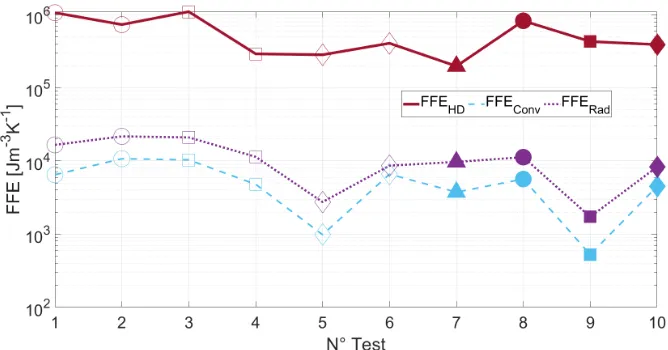
Figure 5: FFE comparison between heat dissipation (TB) and convective (conv) and radiative (rad) parts - Loads : △ : 410 MPa -◯ : 430 MPa -◻ : 450 MPa -◇ : 470
MPa ; Frequencies : Unfilled markers : 5 Hz - Filled markers : 10 Hz
From these tests, it can be seen that the components of convection and radiation are negligible compared to pure conduction (the ratio ofF F Econv+
F F Erad toF F ET B is on average equal to 3.13%, see figure 5).
The results presented in figure 6 show an important part of the FFE ated during the first phase (non stationary phase) of the fatigue test i.e. cre-ated by the initial work hardening (F F Eac,j+F F Eco,j orF F Eac,j+F F Ed1,j).
After this phase, strain is converted into heat almost steadily, leading to sta-ble fatigue entropy generation (F F Eco,j or F F Ed1,j). The convection and
radiation parts appear marginal during the fatigue test. The quantityF F Ec
shows two tendencies, entropy accumulates very quickly (fast burst) in the unsteady phase and then tends to stabilise (seems to be linear) in the sta-tionary phase. Moreover, the results show positive F F ET B,c and positive
Figure 6: Time rate of the generated fatigue entropy F F E˙ j and cumulative generated
fatigue entropy F F Ec calculated for the test N○2 (430 MPa - 5Hz) as a function of the
number of cycles
5.2. Exergy of plastic deformation
The results of the exergy of plastic deformation are plotted in figure 7. These results consolidate the FFE results where a threshold of exergy of plastic deformation seems to exist. The advantage of the exergy of plastic deformation is that it takes into account the influence of the environment on the irreversibility of the thermodynamical system and compares different tests under various environmental conditions. Even if, there is no significant difference between the evolution of the F F E and xp, it can be seen that
taking into account the environment temperature acts as a normalisation. Like theF F Ej, estimating axpj between[tj, tj+1]shows that the material
Figure 7: Exergy of plastic deformation dissipated during fatigue for each test, obtained by two experimental methods (TB and TF) and the empirical model (PN) - Loads : △:
410 MPa -◯ : 430 MPa -◻: 450 MPa -◇: 470 MPa ; Frequencies : Unfilled markers
: 5 Hz - Filled markers : 10 Hz
Figure 8: Time rate of the exergy ˙xjpand cumulative exergyxpcfor the test N○2 (430 MPa
- 5 Hz) as a function of the number of cycles
6. Conclusion and perspectives
formulation, fracture fatigue entropy (FFE) was estimated based on temper-ature measurements (where emissivity uncertainty is shown to have a small influence on the FFE estimation). Estimation of the FFE from a mechan-ical empirmechan-ical model was also preformed. The various estimations seem to converge towards the fact that a constant FFE exists, where the Park and Nelson empirical model (corrected with the prefactor for mean stress) pro-duces a value in accordance with the experimental determination procedure for well-chosen material parameters (UML parameters in this case). In this study, the influence of environment through convective and radiative parts are negligible, and in terms of exergy of plastic deformation, the results con-firm the existence of a threshold. It can be noticed that, atR=0, the primary short non stationary phase of tests produces a large amount of entropy and exergy due to the initial work hardening of the material. During the second longer stationary phase, the level of generated entropy and exergy stabilises until failure, indicating a quasi linear evolution of the damage.
Further tests would be appropriate to verify the independence of the testing parameter in a broader range of loadings and frequencies. Also, new tests will be conducted in specific environments where temperature, pressure or chemical potential can vary, in which the use of the exergy of plastic deformation may become the quantity to be studied replacing the fracture fatigue entropy.
Appendix A. Heat transfer coefficient estimation
Appendix A.1. Dimensionless numbers
The specimen is considered as a vertical plate being submitted to natural convection of air. To estimate heat transferred by convection, we need to estimate the convective heat transfer coefficient. This coefficient is related to the Nusselt number expressed as:
N u=hconvLc λF
(A.1)
In natural convection the dimensionless numbers of interest are the Prandtl number and the Grashof number (their product being the Rayleigh number) expressed as:
Ra=GrP r=gβc(Tm−T0)L
3
νF TνF h
Thermophysical properties of air are evaluated at the film temperature, i.e. using a mean temperature taken between the vertical surface tempera-ture of the specimen and the air temperatempera-ture calculated from the empirical formulas in [77]. The estimation of the Nusselt number (and thus hconv) is
possible using the natural convection correlations on the Rayleigh number from the literature.
Appendix A.2. Correlations
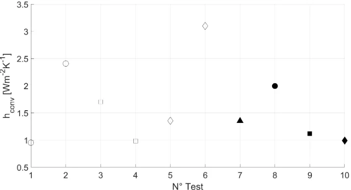
Several correlations (equations (A.3),(A.4),(A.5) from [32] and equation (A.6) from [78]) exist for vertical plates submitted to natural convection leading to very close results for the convective heat transfer coefficient. The mean estimation (using an average on all the correlations) obtained for the convective heat transfer coefficient for each tests is plotted in figure A.9.
N u=
⎛ ⎜⎜ ⎜⎜ ⎜⎜ ⎝
0.825+ 0.387Ra
1/6
[1+ (0.492
P r )
9/16
]
8/27
⎞ ⎟⎟ ⎟⎟ ⎟⎟ ⎠
2
(A.3)
N u=A(GrP r)1/4
A4 = P r
2.43478+4.884P r1/2+4.95283P r (A.4)
N u=0.667( P r 0.952+P r)
1/4 Ra1/4
(A.5)
N u=0.59Ra1/4
104<Ra<109 N u=0.13Ra1/3
109<Ra<1013 (A.6) We have here considered that our specimen was smooth, in the case of a rough surface, other correlations have to be used [79]. In addition, the former correlations are valid for specimens which are not moving. In our case, the loading implies a slight displacement which has to be studied.
Appendix A.3. Correlations validity
Figure A.9: Mean convective coefficient obtained from the calculation of the different Nusselt numbers given in equations (A.3) to (A.6) - Loads : △: 410 MPa -◯: 430 MPa
-◻: 450 MPa - ◇: 470 MPa ; Frequencies : Unfilled markers : 5 Hz - Filled markers :
10 Hz
components can be compared using the Richardson number (ratio of Grashof number to the squared Reynolds number) :
Ri= Gr Re2 =
gβc(Tp−T0)L
v2 (A.7)
An order of magnitude of the velocity imposed by the specimen can be ob-tained considering that the velocity is near the velocity of the specimen in the elastic loading regime. Using table.1 and table.2, and the fact that the loading varies from 0 to maximal amplitude during the time (1/2f)where f
is the loading frequency, the worst case scenario (12 kN - 10 Hz) gives the mean velocity as :
v = ∆l
∆t ≈ (
∆σ Ey )
L
∆t =6.2×10 −3
ms−1
(A.8)
The Richardson number is then approximately (taking Tm−T0=1K):
Ri= 9.81× (1/293.15) ×1×5.7×10 −2
We see here that the fluid flow is driven by the natural convection, and the velocity being small, the correlations for vertical planes are sufficient.
Appendix B. Emissivity error influence
When studying a particular range of wavelength[λ1, λ2], one can perform
the irradiance integration considering fractions of emitted power [80]:
∫λ1λ2Lλdλ= [f(λ2T) −f(λ1T)]ςT4 (B.1)
With :
f(λT) = 15 π4
∞
∑
m=1 emξ
m4 (6+6(mξ) +3(mξ)
2+ (mξ)3) ξ= hpcl
kbλT
(B.2)
The comparison between black body and real body radiation is defined by the emission factor (ε) through a ratio between the black body irradiance and the real body irradiance (in the same conditions):
ελ(λ, T, θ) =
Lλ(λ, T, θ)
L0
λ(λ, T)
(B.3)
This factor is comprised between 0 and 1, and depends on the wavelength, temperature, emission angle, the material under study, its surface condition and optical parameters. From this factor, one can evaluate the irradiance temperature Tλ which is the temperature of a body if it was a black body.
In the case of a range of wavelength, we have:
∫λLλ(T) = ∫ λ
ελL0λ(T) = ∫ λ
L0
λ(Tλ) (B.4)
intercept. In the convection part and in the estimation based on the expo-nential fit, environment temperature and material temperature are shifted thus temperature difference does not change. Finally, the only part chang-ing is the radiative part, where the radiative equivalent transfer coefficient becomes (using Pascal’s triangle):
h′
rad= 4(ε−c1)ς(T0+c2)3 (B.5)
h′
rad= 4εςT
3 0
²h
rad
+ [(3T02×c2) + (3T0×c22) +c32] −4c1ς(T0+c2)3 (B.6)
With: T0 ≈18.7○C, h0 ≈5.36W m−2K−1 and c1 = {0.05; 0.1} and c2 = {3; 6}.
The calculation of the corrected radiative equivalent transfer coefficient im-plies h′
rad = {5.23; 5.10}W m
References
[1] A. Wohler, Uber die Festigkeitsversuche mit Eisen und Stahl, 1870.
[2] L. F. Coffin, A note on low cycle fatigue laws, Journal of Materials 6 (2) (1971) 388 – 402.
[3] S. S. Manson, Interpretive report on cumulative fatigue damage in the law cycle range, Welding Journal Research 43 (1964) 344 – 352.
[4] S. S. Manson, Fatigue : A complex subject - some simple approxima-tions, Experimental Mechanics 5 (1964) 193 – 226.
[5] M. A. Miner, Cumulative damage in fatigue, Journal of Applied Me-chanics 67 (1945) 159 – 164.
[6] J. Morrow, Cyclic plastic strain energy and fatigue of metals, ASTM STP 378 (1965) 45 – 87.
[7] G. R. Halford, The energy required for fatigue, Journal of Materials 1 (1966) 3 – 18.
[8] J. Park, D. Nelson, Evaluation of an energy-based approach and a critical plane approach for predicting constant amplitude multiaxial fatigue life, International Journal of Fatigue 22 (1) (2000) 23 – 39. doi:http://dx.doi.org/10.1016/S0142-1123(99)00111-5.
URL http://www.sciencedirect.com/science/article/pii/
S0142112399001115
[9] J.-H. Park, J.-H. Song, Detailed evaluation of methods for estimation of fatigue properties, International Journal of Fatigue 17 (5) (1995) 365 – 373. doi:http://dx.doi.org/10.1016/0142-1123(95)99737-U.
URL http://www.sciencedirect.com/science/article/pii/
014211239599737U
[10] A. Fatemi, A. Plaseied, A. Khosrovaneh, D. Tanner, Applica-tion of bi-linear loglog sn model to strain-controlled fatigue data of aluminum alloys and its effect on life predictions, In-ternational Journal of Fatigue 27 (9) (2005) 1040 – 1050. doi:http://dx.doi.org/10.1016/j.ijfatigue.2005.03.003.
URL http://www.sciencedirect.com/science/article/pii/
[11] Q. Guo, X. Guo, J. Fan, R. Syed, C. Wu, An energy method for rapid evaluation of high-cycle fatigue parameters based on intrinsic dissipation, International Journal of Fatigue 80 (2015) 136 – 144. doi:http://dx.doi.org/10.1016/j.ijfatigue.2015.04.016.
URL http://www.sciencedirect.com/science/article/pii/
S0142112315001322
[12] G. Meneghetti, M. Ricotta, The use of the specific heat loss to analyse the low- and high-cycle fatigue behaviour of plain and notched specimens made of a stainless steel, Engineering Fracture Mechanics 81 (2012) 2 – 16. doi:http://dx.doi.org/10.1016/j.engfracmech.2011.06.010.
URL http://www.sciencedirect.com/science/article/pii/
S0013794411002347
[13] F. Maquin, F. Pierron, Heat dissipation measurements in low stress cyclic loading of metallic materials: From internal friction to micro-plasticity, Mechanics of Materials 41 (8) (2009) 928 – 942. doi:https://doi.org/10.1016/j.mechmat.2009.03.003.
URL http://www.sciencedirect.com/science/article/pii/
S0167663609000696
[14] A. Kahirdeh, M. Khonsari, Energy dissipation in the course of the fatigue degradation: Mathematical derivation and experimental quan-tification, International Journal of Solids and Structures 77 (2015) 74 – 85. doi:http://dx.doi.org/10.1016/j.ijsolstr.2015.06.032.
URL http://www.sciencedirect.com/science/article/pii/
S0020768315002966
[15] M. Bryant, M. Khonsari, F. Ling, On the thermodynamics of degradation, Proceedings of the Royal Society of London A: Mathemat-ical, Physical and Engineering Sciences 464 (2096) (2008) 2001–2014. arXiv:http://rspa.royalsocietypublishing.org/content/464/2096/2001.full.pdf, doi:10.1098/rspa.2007.0371.
URL http://rspa.royalsocietypublishing.org/content/464/
2096/2001
arXiv:https://doi.org/10.1063/1.1287778, doi:10.1063/1.1287778.
URL https://doi.org/10.1063/1.1287778
[17] M. Amiri, M. Naderi, M. Khonsari, An experimental approach to eval-uate the critical damage, International Journal of Damage Mechanics 20 (1) (2011) 89–112. arXiv:https://doi.org/10.1177/1056789509343082, doi:10.1177/1056789509343082.
URL https://doi.org/10.1177/1056789509343082
[18] C. Basaran, C.-Y. Yan, A Thermodynamic Frame-work for Damage Mechanics of Solder Joints, Jour-nal of Electronic Packaging 120 (4) (1998) 379–384. arXiv:https://asmedigitalcollection.asme.org/electronicpackaging/article-pdf/120/4/379/4664209/379 1.pdf, doi:10.1115/1.2792650.
URL https://doi.org/10.1115/1.2792650
[19] T. C. Chu, W. F. Ranson, M. A. Sutton, Applications of digital-image-correlation techniques to experimental mechanics, Experimental Me-chanics 25 (3) (1985) 232–244. doi:10.1007/BF02325092.
URL https://doi.org/10.1007/BF02325092
[20] J. D. Carroll, W. Abuzaid, J. Lambros, H. Sehitoglu, High resolution digital image correlation measurements of strain accumulation in fatigue crack growth, International Journal of Fatigue 57 (2013) 140 – 150, fatigue and Microstructure: A special issue on recent advances. doi:https://doi.org/10.1016/j.ijfatigue.2012.06.010.
URL http://www.sciencedirect.com/science/article/pii/
S0142112312002113
[21] A. Kahirdeh, C. Sauerbrunn, H. Yun, M. Modarres, A parametric approach to acoustic entropy estimation for assessment of fatigue damage, International Journal of Fatigue 100 (2017) 229 – 237. doi:https://doi.org/10.1016/j.ijfatigue.2017.03.019.
URL http://www.sciencedirect.com/science/article/pii/
S0142112317301159
doi:10.3390/app7060562.
URL https://www.mdpi.com/2076-3417/7/6/562
[23] A. Keshtgar, C. M. Sauerbrunn, M. Modarres, Structural reliability pre-diction using acoustic emission-based modeling of fatigue crack growth, Applied Sciences 8 (8). doi:10.3390/app8081225.
URL https://www.mdpi.com/2076-3417/8/8/1225
[24] G. Fargione, A. Geraci, G. L. Rosa, A. Risitano, Rapid determination of the fatigue curve by the thermographic method, International Journal of Fatigue 24 (1) (2002) 11 – 19. doi:http://dx.doi.org/10.1016/S0142-1123(01)00107-4.
URL http://www.sciencedirect.com/science/article/pii/
S0142112301001074
[25] G. La Rosa, A. Risitano, Thermographic methodology for rapid determination of the fatigue limit of materials and mechanical com-ponents, International Journal of Fatigue 22 (1) (2000) 65 – 73. doi:http://dx.doi.org/10.1016/S0142-1123(99)00088-2.
URL http://www.sciencedirect.com/science/article/pii/
S0142112399000882
[26] J. Fan, X. Guo, C. Wu, A new application of the in-frared thermography for fatigue evaluation and damage as-sessment, International Journal of Fatigue 44 (2012) 1 – 7. doi:https://doi.org/10.1016/j.ijfatigue.2012.06.003.
URL http://www.sciencedirect.com/science/article/pii/
S0142112312002046
[27] A. Wong, G. Kirby, A hybrid numerical/experimental tech-nique for determining the heat dissipated during low cycle fa-tigue, Engineering Fracture Mechanics 37 (3) (1990) 493 – 504. doi:https://doi.org/10.1016/0013-7944(90)90375-Q.
URL http://www.sciencedirect.com/science/article/pii/
001379449090375Q
URL http://www.sciencedirect.com/science/article/pii/ S0142112307002721
[29] L. Jiang, H. Wang, P. Liaw, C. Brooks, D. Klarstrom, Temperature evolution during low-cycle fatigue of ultimet alloy: experiment and modeling, Mechanics of Materials 36 (1) (2004) 73 – 84, fatigue of Ad-vanced Materials. doi:https://doi.org/10.1016/S0167-6636(03)00032-2.
URL http://www.sciencedirect.com/science/article/pii/
S0167663603000322
[30] M. Amiri, M. M. Khonsari, Rapid determination of fatigue fail-ure based on temperature evolution: Fully reversed bending load, International Journal of Fatigue 32 (2) (2010) 382 – 389. doi:http://dx.doi.org/10.1016/j.ijfatigue.2009.07.015.
URL http://www.sciencedirect.com/science/article/pii/
S0142112309002382
[31] M. Amiri, M. Khonsari, Life prediction of metals under-going fatigue load based on temperature evolution, Materi-als Science and Engineering: A 527 (6) (2010) 1555 – 1559. doi:http://dx.doi.org/10.1016/j.msea.2009.10.025.
URL http://www.sciencedirect.com/science/article/pii/
S092150930901154X
[32] G. Meneghetti, Analysis of the fatigue strength of a stainless steel based on the energy dissipation, International Journal of Fatigue 29 (2007) 81 – 94.
[33] A. Chrysochoos, H. Louche, An infrared image processing to anal-yse the calorific effects accompanying strain localisation, Interna-tional Journal of Engineering Science 38 (16) (2000) 1759 – 1788. doi:http://dx.doi.org/10.1016/S0020-7225(00)00002-1.
URL http://www.sciencedirect.com/science/article/pii/
S0020722500000021
doi:10.1111/ffe.12071.
URL https://onlinelibrary.wiley.com/doi/abs/10.1111/ffe.
12071
[35] A. Risitano, G. Risitano, Cumulative damage evaluation of steel using infrared thermography, Theoretical and Applied Fracture Mechanics 54 (2) (2010) 82 – 90. doi:https://doi.org/10.1016/j.tafmec.2010.10.002.
URL http://www.sciencedirect.com/science/article/pii/
S0167844210000698
[36] A. Risitano, G. Risitano, Cumulative damage evaluation in multiple cycle fatigue tests taking into account energy param-eters, International Journal of Fatigue 48 (2013) 214 – 222. doi:https://doi.org/10.1016/j.ijfatigue.2012.10.020.
URL http://www.sciencedirect.com/science/article/pii/
S0142112312003210
[37] Y. F. Ital’yantsev, Thermodynamic state of deformed solids. report 1. determination of local functions of state, Strength of Materials 16 (2) (1984) 238–241. doi:10.1007/BF01530067.
URL http://dx.doi.org/10.1007/BF01530067
[38] Y. F. Ital’yantsev, Thermodynamic state of deformed solids. re-port 2. entropy failure criteria and their application for simple ten-sile loading problems, Strength of Materials 16 (2) (1984) 242–247. doi:10.1007/BF01530068.
URL http://dx.doi.org/10.1007/BF01530068
[39] P. Whaley, Y. Pao, K. Lin, Numerical simulation of material fatigue by a thermodynamic approach. arXiv:https://arc.aiaa.org/doi/pdf/10.2514/6.1983-977,
doi:10.2514/6.1983-977.
URL https://arc.aiaa.org/doi/abs/10.2514/6.1983-977
[40] C. Basaran, S. Nie, An irreversible thermodynamics theory for damage mechanics of solids, International Journal of Damage Mechanics 13 (3) (2004) 205–223. arXiv:http://ijd.sagepub.com/content/13/3/205.full.pdf+html,
doi:10.1177/1056789504041058.
[41] M. Amiri, M. Modarres, An entropy-based damage characterization, Entropy 16 (12) (2014) 6434. doi:10.3390/e16126434.
URL http://www.mdpi.com/1099-4300/16/12/6434
[42] M. Naderi, M. Amiri, M. M. Khonsari, On the thermodynamic entropy of fatigue fracture, Proceedings of the Royal Society of London A: Mathematical, Physical and Engineering Sciences 466 (2114) (2010) 423–438. doi:10.1098/rspa.2009.0348.
URL http://rspa.royalsocietypublishing.org/content/466/
2114/423
[43] M. Amiri, M. M. Khonsari, On the role of entropy genera-tion in processes involving fatigue, Entropy 14 (1) (2012) 24. doi:10.3390/e14010024.
URL http://www.mdpi.com/1099-4300/14/1/24
[44] M. Khonsari, M. Amiri, Introduction to thermodynamics of Mechanical Fatigue, CRC press, Boca Raton, 2017.
[45] M. Liakat, M. Khonsari, Entropic characterization of metal fatigue with stress concentration, International Journal of Fatigue 70 (2015) 223 – 234. doi:http://dx.doi.org/10.1016/j.ijfatigue.2014.09.014.
URL http://www.sciencedirect.com/science/article/pii/
S0142112314002424
[46] M. Liakat, M. Khonsari, On the anelasticity and fatigue fracture entropy in high-cycle metal fatigue, Materials and Design 82 (2015) 18 – 27. doi:http://dx.doi.org/10.1016/j.matdes.2015.04.034.
URL http://www.sciencedirect.com/science/article/pii/
S0261306915002162
[47] M. Naderi, M. Khonsari, Real-time fatigue life monitoring based on thermodynamic entropy, Structural Health Monitoring 10 (2) (2011) 189–197. arXiv:https://doi.org/10.1177/1475921710373295, doi:10.1177/1475921710373295.
URL https://doi.org/10.1177/1475921710373295
doi:http://dx.doi.org/10.1016/j.ijsolstr.2009.12.005.
URL http://www.sciencedirect.com/science/article/pii/
S0020768309004703
[49] M. Naderi, M. Khonsari, A thermodynamic approach to fa-tigue damage accumulation under variable loading, Materi-als Science and Engineering: A 527 (23) (2010) 6133 – 6139. doi:http://dx.doi.org/10.1016/j.msea.2010.05.018.
URL http://www.sciencedirect.com/science/article/pii/
S0921509310005307
[50] V. L. Ontiveros, M. Modarres, M. Amiri, Estimation of reliability of structures subject to fatigue loading using plastic strain energy and thermodynamic entropy generation, Proceedings of the Institution of Mechanical Engineers, Part O: Journal of Risk and
Reliabilit-yarXiv:http://pio.sagepub.com/content/early/2015/02/27/1748006X15574143.full.pdf+html, doi:10.1177/1748006X15574143.
URL http://pio.sagepub.com/content/early/2015/02/27/
1748006X15574143.abstract
[51] V. Ontiveros, M. Amiri, A. Kahirdeh, M. Modarres, Thermodynamic entropy generation in the course of the fatigue crack initiation, Fatigue & Fracture of Engineering Materials & Structures 40 (3) (2017) 423– 434. arXiv:https://onlinelibrary.wiley.com/doi/pdf/10.1111/ffe.12506, doi:10.1111/ffe.12506.
URL https://onlinelibrary.wiley.com/doi/abs/10.1111/ffe.
12506
[52] A. Imanian, M. Modarres, A thermodynamic entropy approach to relia-bility assessment with applications to corrosion fatigue, Entropy 17 (10) (2015) 6995–7020. doi:10.3390/e17106995.
URL https://www.mdpi.com/1099-4300/17/10/6995
[53] J. Wang, Y. Yao, An entropy based low-cycle fatigue life prediction model for solder materials, Entropy 19 (10). doi:10.3390/e19100503.
URL https://www.mdpi.com/1099-4300/19/10/503
[54] H. Yun, M. Modarres, Measures of entropy to characterize fatigue dam-age in metallic materials, Entropy 21 (8). doi:10.3390/e21080804.
[55] J. A. Osara, M. D. Bryant, Thermodynamics of fatigue: Degradation-entropy generation methodology for system and process characterization and failure analysis, Entropy 21 (7). doi:10.3390/e21070685.
URL https://www.mdpi.com/1099-4300/21/7/685
[56] Y.-J. Sun, L.-S. Hu, Assessment of Low Cycle Fatigue Life of Steam Turbine Rotor Based on a Thermodynamic Approach, Jour-nal of Engineering for Gas Turbines and Power 134 (6), 064504. arXiv:https://asmedigitalcollection.asme.org/gasturbinespower/article-pdf/134/6/064504/4792196/064504 1.pdf, doi:10.1115/1.4006004.
URL https://doi.org/10.1115/1.4006004
[57] S. F. Karimian, H. A. Bruck, M. Modarres, Thermodynamic entropy to detect fatigue crack initiation using digital image correlation, and effect of overload spectrums, International Journal of Fatigue 129 (2019) 105256. doi:https://doi.org/10.1016/j.ijfatigue.2019.105256.
URL http://www.sciencedirect.com/science/article/pii/
S0142112319303603
[58] H. Salimi, M. Pourgol-Mohammad, M. Yazdani, Metal fatigue assess-ment based on temperature evolution and thermodynamic entropy generation, International Journal of Fatigue 127 (2019) 403 – 416. doi:https://doi.org/10.1016/j.ijfatigue.2019.06.022.
URL http://www.sciencedirect.com/science/article/pii/
S014211231930252X
[59] M. Liakat, M. Khonsari, An experimental approach to esti-mate damage and remaining life of metals under uniaxial fa-tigue loading, Materials and Design 57 (2014) 289 – 297. doi:http://dx.doi.org/10.1016/j.matdes.2013.12.027.
URL http://www.sciencedirect.com/science/article/pii/
S0261306913011606
[60] M. Liakat, M. Khonsari, Rapid estimation of fatigue entropy and toughness in metals, Materials and Design (1980-2015) 62 (2014) 149 – 157. doi:http://dx.doi.org/10.1016/j.matdes.2014.04.086.
URL http://www.sciencedirect.com/science/article/pii/
[61] M. Mehdizadeh, M. Khonsari, On the role of internal friction in low-and high-cycle fatigue, International Journal of Fatigue 114 (2018) 159 – 166. doi:https://doi.org/10.1016/j.ijfatigue.2018.05.007.
URL http://www.sciencedirect.com/science/article/pii/
S0142112318301786
[62] M. Mehdizadeh, M. Khonsari, On the application of fracture fatigue entropy to variable frequency and loading amplitude, Theoretical and Applied Fracture Mechanics 98 (2018) 30 – 37. doi:https://doi.org/10.1016/j.tafmec.2018.09.005.
URL http://www.sciencedirect.com/science/article/pii/
S016784421830329X
[63] J. Lemaitre, J. Chaboche, Mechanics of Solid Materials, Cambridge Uni-versity press, Cambridge UK, 1990.
[64] A. B¨aumel, T. Seeger, Materials data for cyclic loading, Elsevier Science Publishers, 1990.
[65] M. Meggiolaro, J. Castro, Statistical evaluation of strain-life fatigue crack initiation predictions, International Journal of Fatigue 26 (5) (2004) 463 – 476. doi:http://dx.doi.org/10.1016/j.ijfatigue.2003.10.003.
URL http://www.sciencedirect.com/science/article/pii/
S0142112303002469
[66] A. Lipski, S. Mrozi´nski, Approximate determination of a strain-controlled fatigue life curve for aluminum alloy sheets for air-craft structures, International Journal of Fatigue 39 (2012) 2 – 7, physical and phenomenological approaches to fatigue damage. doi:http://dx.doi.org/10.1016/j.ijfatigue.2011.08.007.
URL http://www.sciencedirect.com/science/article/pii/
S0142112311002064
[67] A. Ince, G. Glinka, A modification of morrow and smithwatsontopper mean stress correction models, Fatigue & Fracture of Engineer-ing Materials & Structures 34 (11) 854–867. doi:10.1111/j.1460-2695.2011.01577.x.
URL https://onlinelibrary.wiley.com/doi/abs/10.1111/j.
[68] N. E. Dowling, Mean stress effects in stress-life and strain-life fatigue, in: SAE Technical Paper, SAE International, 2004. doi:10.4271/2004-01-2227.
URL https://doi.org/10.4271/2004-01-2227
[69] T. Boulanger, A. Chrysochoos, C. Mabru, A. Galtier, Calorimetric analysis of dissipative and thermoelastic effects associated with the fatigue behavior of steels, International Journal of Fatigue 26 (3) (2004) 221 – 229. doi:http://dx.doi.org/10.1016/S0142-1123(03)00171-3.
URL http://www.sciencedirect.com/science/article/pii/
S0142112303001713
[70] A. Blanche, A. Chrysochoos, N. Ranc, V. Favier, Dissipation assess-ments during dynamic very high cycle fatigue tests, Experimental Me-chanics 55 (4) (2015) 699–709. doi:10.1007/s11340-014-9857-3.
URL http://dx.doi.org/10.1007/s11340-014-9857-3
[71] A. Chrysochoos, J.-C. Chezeaux, H. Caumon, Analyse ther-mom´ecanique des lois de comportement par thermographie in-frarouge, Rev. Phys. Appl. (Paris) 24 (2) (1989) 215–225. doi:10.1051/rphysap:01989002402021500.
URL http://dx.doi.org/10.1051/rphysap:01989002402021500
[72] A. Chrysochoos, R. Peyroux, Analyse exp´erimentale et mod´elisation num´erique des couplages thermom´ecaniques dans les mat´eriaux solides, Revue G´en´erale de Thermique 37 (7) (1998) 582 – 606. doi:http://dx.doi.org/10.1016/S0035-3159(98)80036-6.
URL http://www.sciencedirect.com/science/article/pii/
S0035315998800366
[73] E. M. Pellegrino, E. Ghibaudi, L. Cerruti, Clausius disgregation: A conceptual relic that sheds light on the second law, Entropy 17 (7) (2015) 4500–4518. doi:10.3390/e17074500.
URL http://www.mdpi.com/1099-4300/17/7/4500
[74] M. Gouy, Sur l’´energie utilisable, Journal de physique th´eorique et ap-pliqu´ee 8 (1) (1889) 501 – 518.
[76] P. Ribeiro, D. Queiros-Cond´e, L. Grosu, L. Gallimard, An exergetic approach for materials fatigue, International Journal of Exergy 22 (3) (2017) 235–249. doi:10.1504/IJEX.2017.083172.
URL https://www.inderscienceonline.com/doi/abs/10.1504/
IJEX.2017.08317
[77] J. C. Dixon, Appendix B: Properties of Air, Wiley-Blackwell, 2007, pp. 375–378. doi:10.1002/9780470516430.app2.
URL https://onlinelibrary.wiley.com/doi/abs/10.1002/
9780470516430.app2
[78] B. Eyglunent, Manuel de thermique th´eorie et pratique (2e ´ed.), Herm`es, 1997.
[79] M. Ashjaee, M. Amiri, J. Rostami, A correlation for free convection heat transfer from vertical wavy surfaces, Heat and Mass Transfer 44 (1) (2007) 101–111. doi:10.1007/s00231-006-0221-8.
URL http://dx.doi.org/10.1007/s00231-006-0221-8
[80] M. F. Modest, Radiative heat transfer, 3rd Edition, Elsevier, 2013.