ADDENDUM TO ISSUE 4 OF THE
INTER-TEL AXXESS SYSTEM MANUAL
For Software Part Numbers: 827.8658, 827.8659, 827.8660, 827.8661, and 827.8662
This addendum describes feature, programming, and hardware changes that apply when the AXXESS System is installed with the version 4.3 software part numbers listed above. It also includes changes and corrections to Issue 4 of the AXXESS Installation and Field Maintenance Manual. For software installation instructions, refer to the manu-al or to the document included with the software components. The new system software is identicmanu-al to the previous version of software, except for the changes and corrections described on these pages. Refer to the manual for detailed system information.
FEATURE, PROGRAMMING, AND
HARDWARE CHANGES
New Software Part Numbers
The part numbers for the new version 4.3 software are:
SOFTWARE PART NO.
Premium Software for CPU/MEM Card
(15 ROMs)
827.8659
Premium Software for CPU020/PCM
Card (two floppy disks)
827.8658
Database Programming Software (three floppy disks)
827.8662
AXXESSORYTalk Applications Software for OS/2 (five floppy disks)
827.8660
AXXESSORYTalk Applications Software for Windows NT (five floppy disks)
827.8661
AXXESSORYTalkOS/2 Japanese Voice Prompts (four floppy disks)
827.8592
AXXESSORY Talk NT Japanese Voice Prompts (three floppy disks)
827.8742
Changes and New Features in the 4.3
Software Release
New 4.3 features and changes described in this adden-dum include:
• Agent Set (see page 2)
• “Send Alert Burst To Headset” Station Flag (see page 2)
• 16-Circuit Single-Line Card (SLC-16) and Lamp Options Card (see page 3)
• LGC and LGC-D Modification (see page 6) • Call Routing to Public Network (see page 7)
• Station Password (see page 10)
• Remote Feature Programming (see page 12) • Group Listen Feature (see page 13)
• CO Hookflash on Conference Calls (see page 13) • OPX Disconnect Enhancement (see page 14) • Advanced CO Interface Premium Feature
Re-quired for PRI (see page 14)
• Trunk Group PRI Call By Call (see page 14) • OS/2 and NT Versions of AXXESSORY Talk (see
page 16)
• Fax Delivery Report Indicates Failed Deliveries (see page 23)
• AXXESSORY Talk VisualMail (see page 24) • Automatic Fax Detection (see page 31)
• Programming Fax-On-Demand Port availability (see page 33)
• Voice Mail Save/Restore To A Network Drive (see page 34)
• Explanation of Extended Ring Cadences (see page 35)
• RS-232-C Changes and Corrections (see page 36)
Changes and Features from Previous
Software Releases
Earlier 4.1 and 4.2 features and changes described in this addendum include:
• Preventing Memory Shortages (see page 37) • New CPU020/PCM Card Configurations (see
page 37)
• New CPU/MEM Card Configuration (see page 37) • New Options Card (OPC) Configuration (see page
• New T1 Card (T1C) Revision Level Changes (see page 37)
• T1 Gain Control (TGC) Daughter Card (see page 37)
• DKSC-16 Extended Loop Length Modification (see page 38)
• New Voice Processing Card (VPC) Models (see page 38)
• CPU020/PCM Card Software Installation Infor-mation (see page 38)
• New FCC Part 68 PBX Rating (see page 38) • New Fax Card Models (see page 38) • New PC Motherboard (see page 41) • Config.sys File Change (see page 41) • ACD Agent IDs (see page 43)
• Primary Rate T1 Service (see page 50)
• Customized AXXESSORY Talk Prompts (see page 53)
• Digital Keyset Enhancements (see page 60) • “Enable Database Server Compression”
Prefer-ences Flag (see page 63)
• “Forced Delayed Major Reset” System Flag (see page 64)
• “CO Provides Progress Tones” T1 Programming Flag (see page 65)
• Canadian Information (see page 66)
• Changes and Corrections to the Issue 4 Manual (see page 67)
Agent Set
The Agent Set is used in place of a keyset with an at-tached PCDPM. It is connected to a Digital Keyset Card (DKSC or DKSC-16) port just as a keyset would be.
It has a jack for plugging in an Inter-Tel handset or headset. It also has a serial connector (DB9) for attach-ing it to a PC.
The Agent Set does not require a transformer or exter-nal power source.
To operate properly, the Agent Set must be pro-grammed for headset mode. This can be done in one of the following ways:
• Enable Headset Mode via Station Programming in the AXXESS or Axxent System database • At the keyset, unplug the headset or handset (to
take the Agent Set off hook) and enter the Headset On/Off feature code (317) to enable headset mode. Then plug in the headset or handset.
NOTE: There is nothing to prevent the user from dis-abling headset mode using the Headset On/Off feature code at the station.
Because the Agent Set does not have feature keys, a dialing pad, or a speaker, it must be connected to a PC that is equipped with AXXESSORY Connect (or a sim-ilar OAI product that emulates a keyset). The AXXES-SORY Connect is used for dialing and feature access. The Agent Set also requires an Inter-Tel headset or handset. Only Inter-Tel equipment should be used. Other manufacturer’s equipment may not be compat-ible with the Agent Set.
If the user wishes to receive audible signals at the head-set, there is a new station flag (described below) that will send a single tone to the headset when a call is ring-ing.
“Send Alert Burst To Headset” Station
Flag
There is a new station flag that will send a single tone to a headset, instead of normal keyset ring tones, when a call is ringing at the station (non-handsfree intercom call, outside call, queue callback, or reminder mes-sage). The flag, called “Send Alert Burst To Headset,” is programmed on a station-by-station basis.
16-Circuit Single-Line Card (SLC-16) and
Lamp Options Card (LOC-16)
16-Port Single-Line Card (SLC-16)
The SLC-16 can support up to 16 on-premises AC-ring-ing sAC-ring-ingle-line devices. Like the 8-circuit SLC, it does not support off-premises stations and does not have DID capability.
An SLC-16 cannot be installed in a card slot that is pro-grammed for an SLC. The ports must be specifically programmed for an SLC-16. However, if port program-ming is changed from SLC to SLC-16, the existing eight circuits will retain their individual programming and the new circuits will be in the default state. If the port is changed from an SLC-16 to an SLC, all circuits will retain their programming, but only the first eight will be available.
The SLC-16 uses 72VDC to generate trapezoidal ring-ing waveforms, which have the same effect as sine ringing waveforms. The card is capable of delivering a total ringer equivalence number (REN) of 16.0 at a fre-quency of 20Hz (e.g., 1.0 REN per circuit). No single circuit should exceed a REN of 5.0. If the card requires more than 16.0 REN total, use a larger DC power sup-ply (available from Inter-Tel). If a fax machine, mo-dem, or single-line set does not respond to the ringing provided by the SLC-16, consult the manual for that device and/or contact Inter-Tel Technical Support. The loop limit for the SLC-16 is 103 ohms/2000 feet (609 m.).
16-Port Lamp Options Card (LOC-16)
A 16-port Lamp Options Card (LOC-16) is also avail-able to provide visual message waiting capabilities for single-line sets equipped with message lamps. The single-line sets are then configured in database pro-gramming to receive visual and/or audible message waiting indication tones. Except for these differences, the installation and operation of the LOC-16 is similar to that of the 8-port LOC described in the manual:
If installing the optional LOC-16:
a. Carefully remove the two, solid, 16-position jumper straps from jumper locations J3 and J4 on the SLC-16.
b. Place jumper strap (J6) on the SLC-16 in the LOW position (over the top two pins). c. Carefully attach the LOC-16 to jumper
loca-tions J3, J4, and J5 on the SLC-16. Make sure that the connectors are properly aligned and seated.
d. When programming the database, be sure to enable the message waiting lamps in station programming.
Power Supplies
A power supply is required for each SLC-16 because the cards are not designed to pull talk battery, ring, or message lamp power from the system power supply. Power supplies are available that support one card or up to four cards. Refer to the illustration and chart on the next two pages for cable termination information. NOTE: If you receive a power supply with a connector on the wires, the connector will have to be cut off be-fore the power supply can be installed. Also, if a four-card power supply is wall mounted, be sure that the ful-ly-enclosed side is on the bottom (i.e., facing down).
Part Numbers
The new SLC-16, LOC-16, and power supply part numbers are:
SLC-16 550.2116
LOC-16 550.2104
Power Supply for 1 Card 550.0114 Power Supply for up to 4 Cards 550.0116
FIGURE 1.
SLC-16 BLOCK CABLE TERMINATIONS
G Y
R BK
1.1 1.1
1.2
BL/W RING W/BL TIP
TIP RING
W/BL BL/W W/O O/W W/G G/W
Y/G G/Y Y/BR
SINGLE-LINE CARD
AMPHENOL-TYPE CONNECTOR
SLC-16 MODULAR
JACK ASSEMBLY
TO SINGLE-LINE SET OR PLAYBACK DEVICE
66M1-50-TYPE BLOCK
(PART OF MDF)
TIP RING
1.3 TIP RING
GND (BLACK) –48V EXT ((RED)
1.3 1.2
NOTE: For simplicity, this figure shows single-line sets and playback devices being installed using one-pair cable and four-conductor modular jacks. Of course, if three-one-pair cable and six-conductor modular jacks are used instead (as is recommended), extra terminal blocks and the use of cross-connect wiring techniques are required.
Y/BL BL/Y Y/O O/Y
TIP RING NOT USED NOT USED
1.16
G Y
R BK
BL/W RING W/BL TIP
MODULAR JACK ASSEMBLY
TO SINGLE-LINE SET OR PLAYBACK DEVICE 1.16
BR/Y Y/S S/Y
GND (BLACK) –72V EXT (YELLOW) NOT USED
NOT USED
FIGURE 2.
SLC-16 CABLE TERMINATIONS ON THE SLC-16 STATION BLOCK
AMPHENOL NO.
CABLE PAIR
SLC-16
26 W–BL TIP
1 BL–W RING
27 W–O TIP
2 O–W RING
28 W–G TIP
3 G–W RING
29 W–BR TIP
4 BR–W RING
30 W–S TIP
5 S–W RING
31 R–BL TIP
6 BL–R RING
32 R–O TIP
7 O–R RING
33 R–G TIP
8 G–R RING
34 R–BR TIP
9 BR–R RING
35 R–S TIP
10 S–R RING
36 BK–BL TIP
11 BL–BK RING
37 BK–O TIP
12 O–BK RING
38 BK–G TIP
13 G–BK RING
39 BK–BR TIP
14 BR–BK RING
40 BK–S TIP
15 S–BK RING
41 Y–BL TIP
16 BL–Y RING
42 Y–O NOT USED
17 O–Y NOT USED
43 Y–G GND B2 (BLACK) 18 G–Y –48V EXT (RED)
44 Y–BR NOT USED
19 BR–Y NOT USED
45 Y–S GND B1 (BLACK) 20 S–Y –72V EXT (YELLOW)
46 V–BL NOT USED
21 BL–V NOT USED
47 V–O NOT USED
22 O–V NOT USED
48 V–G NOT USED
23 G–V NOT USED
49 V–BR NOT USED
24 BR–V NOT USED
50 V–S NOT USED
Loop/Ground Start Card (LGC) and
LGC Daughter Card (LGC-D)
Modification
Under certain conditions, previous versions of the LGC (part no. 550.2309) and the LGC-D (part no. 550.2310) were not able to always properly detect the “ground start” signal provided by the central office (CO). A modification to the LGC and LGC-D has been imple-mented to correct this problem.
More specifically, the previous versions of the LGC and LGC-D did not function properly in ground-start mode when terminated on a CO trunk that had a constant current battery feed of less than approximately 25mA. The new cards have a built-in 50VDC power supply and therefore no longer rely on the current from the CO to detect the “ground start” signal.
Identifying the Problem
A customer site may have this problem if a keyset user’s display shows “LINE IS UNPLUGGED” when attempting to access a ground start trunk on an LGC or LGC-D. To determine if the card really does have a problem detecting the ground start signal from the CO, follow these steps:
(1) Ensure that the appropriate trunk circuit on the card is programmed for ground start mode. (Loop start mode is not subject to this problem.) (2) Verify that the card is properly installed and connected as outlined in the AXXESS
Installa-tion & Field Maintenance Manual.
(3) Verify that tip and ring for the trunk circuit are properly connected. Here is a simple method that works for most cases:
a. At the associated CO block, remove the bridging clips for the trunk.
b. On the telco side of the block, attach a test set (butt set) in monitor mode (on-hook) to tip and ring.
c. Apply ground to the ring terminal.
d. If you hear dial tone (only while ground is
applied), tip and ring are properly
con-nected. Replace the bridging clips and check
to make sure the card can still receive dial tone.
If you do not hear dial tone, apply ground to
the tip terminal. If you now hear dial tone, tip and ring are reversed.
NOTE: Be sure the test set is in monitor mode. If it is in off-hook mode, sometimes the line can be seized regardless of the polar-ity, and the test is invalid.
Identifying the Modified Cards
Remove the LGC and/or LGC-D and look at the part number stenciled on the card. Immediately after the part number, there should be a dash (–) and a single letter contained within a box. This denotes the revision level of the card. The following chart shows the revi-sion level of the current, modified cards:
CARD PART NO. ECN NO. REVISION
LGC 550.2309 4813 826.5223–4D
(or higher) 826.5223–5D (or higher) 826.5223–6
(any letter) LGC-D 550.2310 4814 826.5224–3B (or higher) 826.5224–4B (or higher) 826.5224–5
(any letter)
Compatibility
Improperly paired cards will not work together and the trunks attached to these cards will not function. LGC –6 cards will only work with LGC-D –5 cards (and visa versa). They are not backwards compatible. LGC –4 and –5 cards will only work with either LGC-D –3 and –4 cards.
Resolution
Call Routing to Public Network
This feature changes the AXXESS system in the fol-lowing ways:
• Call Routing Tables can be programmed to route outside calls to outgoing trunks, using Automatic Route Selection (ARS) or a trunk group. However, Primary Rate trunks can be used only through ARS; individual B-channel trunks or trunk groups containing B-channel trunks will not function properly with this feature.
• The system provides a means for the trunk-to-trunk call to be supervised including normal trunk dis-connect supervision and timer disdis-connect supervi-sion.
• Toll restriction will be enforced on call attempts made from one trunk to another trunk or trunk group (but not on trunk-to-ARS calls).
Access To Outgoing Trunks
Call Routing Tables now allow patterns that route calls to destinations of individual trunks, trunk groups, and ARS anywhere single ring-in destinations are pro-grammed.
If the caller is routed to a trunk or trunk group that is busy, the system will camp on to the trunk. The caller will hear busy tones, followed by music. When a trunk becomes available, the caller hears dial tone and can complete the call.
Toll Restriction
To provide security on outgoing calls made through di-rect trunk-to-trunk interfaces, the toll restriction of the selected outgoing trunk will be checked. However, if ARS is used, toll restriction is not checked.
The toll restriction of the incoming trunk’s group and that trunk’s “Subject To Toll Restriction” flag are not checked.
If a caller dials a number that is not allowed through toll restriction, the call will be routed to the primary atten-dant.
Programming Call Routing Tables
Call Routing to the Public Network is programmed through the Call Routing Table screens for program-ming Individual Patterns, Area Code Batch Inserts, or Batch Ring-In Destinations, as shown on the next page.
Even though Primary Rate trunks appear in the selec-tion lists, they can only be used by selecting ARS; indi-vidual channel trunks or trunk groups containing B-channel trunks will not function properly with this feature.
NOTE: This cannot be programmed if you enter data-base programming using the “User” password and it cannot be programmed through an Administrator’s keyset.
NOW YOU CAN CHOOSE ARS,
NOW YOU CAN CHOOSE ARS,
TRUNKS, OR TRUNK GROUPS
NOW YOU CAN CHOOSE ARS,
SMDR and Message Print Changes To Support Call Routing To The Public Network
Several changes have been made to the Station Mes-sage Detail Recording (SMDR) feature to support Call Routing to the Public Network.
You can choose which trunks to include in the SMDR report. This is done through the SMDR Programming screen (shown below), just as it was for including
sta-tions. A new Trunks command button has been added that displays a selection screen (shown at the bottom of the page). The SMDR window also includes a new check box for “Record All Trunk to Trunk Calls.” This will include calls, made from one outside caller to another, in the SMDR report.
An outgoing call that has been initiated by another trunk will show the initiating trunk’s number in the “EXT” field of the SMDR report.
←NEW BUTTON
Station Password
A station password has been added to the system. This password is used for the new Remote Programming feature.
The station password can be up to 8 digits in length. The default password is the extension number of the station. The password can be changed by entering the Program Station Password feature code at the station or when using the new Remote Programming feature (de-scribed in detail on page 12). It can also be pro-grammed through Individual Station programming, as described on page 12.
If the new password is programmed from a station, the user will be prompted for the old password, then the new password, and will be asked to verify the new pass-word. If it is programmed through Remote Program-ming, the user will already have entered a correct pass-word, so the user is only prompted for the new password and will be asked to verify the password. Should the verified password and new password not match, the old password will be retained and the pro-gramming session canceled.
TO CHANGE THE STATION PASSWORD FROM YOUR STATION:
(4) Enter the Program Station Password feature code (392). You hear a confirmation tone. If you have a display, it shows ENTER PASSWORD. (5) Enter your current password, followed by #. (At default it is your extension number.) If you have a display, it shows NEW PASSWORD. NOTE: If you enter an incorrect password, the display will show INVALID PASSWORD and your station will return to the idle state. (6) Enter the new password followed by #. You hear
a confirmation tone.
(7) Enter the new password again for verification followed by #. You hear a confirmation tone. If you have a display, it shows PASSWORD SAVED. Your station returns to the idle state.
TO CHANGE THE STATION PASSWORD USING REMOTE PRO-GRAMMING:
(1) If calling from an outside telephone, access the
system through a DISA line. Enter the DISA se-curity code (if applicable). You hear a confirma-tion tone.
If programming from another station, lift the
handset or press the SPKR key.
(2) Enter the Remote Programming feature code (359). You hear a confirmation tone. If you have a display, it shows ENTER EXTENSION. (Executive Keyset users can press the IC DIR key to use the intercom directory to look up a number.)
(3) Enter the extension to be programmed. You hear a confirmation tone. If you have a display, it shows ENTER PASSWORD. If you entered
an invalid extension number, you will hear
reor-der tones and can try again.
(4) Enter the extension’s password followed by #. You hear a confirmation tone.
NOTE: If you enter an incorrect password, the display will show INVALID PASSWORD. Out-side callers will be returned to dial tone and sta-tions will return to the idle state.
(5) Enter the Program Station Password feature code (392). You hear a confirmation tone. If you have a display, it shows NEW PASSWORD. (6) Enter the new password, followed by #. You
hear a confirmation tone.
(7) Enter the new password again for verification, followed by #. You hear a confirmation tone. If you have a display, it shows PASSWORD SAVED. Outside callers will hear dial tone and stations return to the idle state.
The Program Station Password feature code (392) is now included in the Extensions, Usernames, and Fea-ture Codes programming screen.
←NEW BUTTON
To change the station password through database pro-gramming, use the screen shown above. It can be reached by selecting Miscellaneous Station Informa-tion from the Individual StaInforma-tion InformaInforma-tion program-ming screen.
NOTE: This cannot be programmed if you enter data-base programming using the “User” password and it cannot be programmed through an Administrator’s keyset.
PASSWORD: When you select the Password com-mand button, the following window appears. Enter the desired password, up to eight digits, and select OK. (Or,
Remote Feature Programming
The Remote Programming feature allows a user to place a phone in do-not-disturb mode (DND) or for-ward the station’s calls, either from another station or through DISA.
The Remote Programming feature code (359) is now included in the Extensions, Usernames, and Feature Codes programming screen.
Do-Not-Disturb Programming
TO PLACE A STATION IN DO-NOT-DISTURB MODE USING THE REMOTE PROGRAMMING FEATURE:
NOTE: After each entry, non-display keyset users will hear a confirmation tone. Outside callers using a DISA line will hear confirmation tone followed by DISA dial tone. Display keyset users will not hear confirmation tones but will see a prompt asking for the next entry. (1) If calling from an outside telephone, access the
system through a DISA line. Enter the DISA se-curity code (if applicable). You hear a confirma-tion tone followed by DISA dial tone.
If programming from another station, lift the
handset or press the SPKR key.
(2) Enter the Remote Programming feature code (359). If you have a display, it shows ENTER EXTENSION. (Executive Keyset users can press the IC DIR key to use the intercom direc-tory to look up a number.)
(3) Enter the extension to be placed in DND. If you have a display, it shows ENTER PASSWORD.
If you entered an invalid extension number, you
will hear reorder tones and can try again. (4) Enter the extension’s password, followed by #.
If you have a display, it shows ENTER FEA-TURE CODE.
NOTE: If you enter an incorrect password, the display will show INVALID PASSWORD and the call is disconnected. Station users will hear reorder tones.
(5) To turn on Do-Not-Disturb:
a. Enter the Do-Not-Disturb On feature code (370). (The On/Off feature code cannot be used in remote programming.) If you entered
an invalid feature code, you will hear
reor-der tones and can try again.
NOTE: If the station you are programming
is not allowed to use DND, you will hear
re-order tones and the display will show CAN-NOT ACCESS RESERVED FEATURE.
Outside callers will be returned to dial tone and stations will return to the idle state. b. Enter the desired do-not-disturb message
number (01–20). If you entered an invalid
message number, you will hear reorder tones
and can try again.
c. Enter the optional second-line message text, if desired, using any combination of the fol-lowing methods:
Remain in numeric mode: Press the keypad
keys to enter the desired number. Use the pound key (#) for a hyphen (–) and the aster-isk key (*) for a colon (:). Keyset users can press the FWD key once to leave a space, or press the MUTE key to backspace.
Change to alphanumeric mode (keysets only): Press the MSG key (the key lights) or
the USE ALPHA MODE menu key, then en-ter the desired characen-ters. (Refer to the chart and instructions in your user guide.) Keyset users can press the FWD key once to advance or twice to leave a space, or press the MUTE key to backspace.
Use speed-dial and/or redial numbers (key-sets only): In either numeric or
alphanumer-ic mode, you can speed dial a number (using the speed-dial key or feature code). In nu-meric mode you can press the REDIAL key to enter the stored characters. You may chain speed-dial and/or redial numbers to-gether.
d. Hang up to complete the programming. (6) To turn off Not-Disturb: Enter the
Do-Not-Disturb Off feature code (371). (The On/ Off feature code cannot be used in remote pro-gramming.) The call is automatically disconnected when the feature code is accepted.
If you entered an invalid feature code, you will
hear reorder tones and can try again. Remote Forward Programming
TO FORWARD A STATION USING THE REMOTE PROGRAMMING FEATURE:
NOTE: After each entry, non-display keyset users will hear a confirmation tone. Outside callers using a DISA line will hear confirmation tone followed by DISA dial tone. Display keyset users will not hear confirmation tones but will see a prompt asking for the next entry. (1) If calling from an outside telephone, access the
se-curity code (if applicable). You hear a confirma-tion tone followed by DISA dial tone.
If programming from another station, lift the
handset or press the SPKR key.
(2) Enter the Remote Programming feature code (359). If you have a display, it shows ENTER EXTENSION. (Executive Keyset users can press the IC DIR key to use the intercom direc-tory to look up a number.)
(3) Enter the extension to be forwarded. If you have a display, it shows ENTER PASSWORD. If you
entered an invalid extension number, you will
hear reorder tones and can try again.
(4) Enter the extension’s password, followed by #. If you have a display, it shows ENTER FEA-TURE CODE.
NOTE: If you enter an incorrect password, the display will show INVALID PASSWORD and the call is disconnected. Station users will hear reorder tones.
(5) To turn on Call Forward:
a. Enter one of the following Call Forward fea-ture codes. If you entered an invalid feafea-ture
code, you will hear reorder tones and can try
again.
Call Forward All Calls. . . 355 Call Forward If Busy . . . 357 Call Forward If No Answer. . . 356 Call Forward If No Answer/Busy . . . 358 b. Enter the forwarding destination. This can be an extension number or a trunk access code followed by an outside telephone num-ber.
If the forward destination is an extension number, programming is complete and the
call is disconnected automatically.
If the forward destination is an outside num-ber, hang up to complete the programming.
If the station is not permitted to forward to the destination entered, you will hear
reor-der tones and can try again.
If you hang up before entering a forward destination, the programmed forward is
can-celed.
(6) To turn off Call Forward: Enter 355 and then hang up instead of entering a destination. You hear a confirmation tone.
Group Listen Feature (Keysets Only)
The Group Listen feature allows a keyset user to trans-mit a conversation over the keyset speaker while in handset or headset mode. This allows other people in the room to listen to the conversation. However, the keyset microphone remains disabled so that only the headset or handset user can speak.
This feature cannot be used on a handsfree call. The user must be on a call using the handset or a headset before entering the feature code. Group Listen cannot be used on single-line sets.
TO TURN THE GROUP LISTEN FEATURE ON OR OFF DURING A CALL:
While on a call using the handset or a headset, press the Special key and enter the Group Listen feature code (312). You hear a confirmation tone and the display shows GROUP LISTEN ON or GROUP LISTEN OFF. (The other party will not hear the confirmation tone.)
The Group Listen feature code (312) is now included in the Extensions, Usernames, and Feature Codes pro-gramming screen. It is also available through the Executive Keyset display menu.
When the feature is active in handset mode, the SPKR lamp will remain unlit. This allows the user to place the call into handsfree mode at any time during the call by pressing the SPKR key. When the feature is active in headset mode, the SPKR lamp is lit. Pressing the key will disconnect the call.
The Group Listen feature code can be programmed un-der a feature key or DSS/BLF key just like any other feature. The key functions as a toggle. If the key has a lamp, it is lit when the feature is activated and unlit when the feature is turned off.
If the Group Listen feature is active when an OHVA call is received by the keyset, the OHVA call will camp on (because the speaker is busy).
CO Hookflash on Conference Calls
The system now supports the CO Hookflash feature code (330) during a conference call.
TO GENERATE A HOOKFLASH WHILE ON A CONFERENCE CALL:
OPX Disconnect Enhancement
In previous software versions, some sites had difficul-ties when using a loop start T1 line configured for OPX to connect two Inter-Tel systems and performing “semi-networking” applications such as intercom ac-cess, lighting message lamps, and shared voice mail. The reason for the difficulty is that the T1 OPX does not send a disconnect signal to the loop start trunk, which caused trunks to be “locked up.”
The solution was to add a new flag in the 4.3 software version. The station flag, for single-line stations only, is called “Send T1 OPX Disconnect Flash.” It sends a pro-prietary disconnect signal from the T1 OPX to the loop start trunk. (The “A” bit is toggled high for the duration of the SL Disconnect Flash Duration timer.) At default, this flag is disabled.
The “Send T1 OPX Disconnect Flash” flag appears in the Station Miscellaneous Flags screen and the Individ-ual Station/Miscellaneous Flags screen below the “Outside Party Call Information Has Priority” flag. By default the flag is disabled.
To use this new station flag, you must have a T1 Card equipped with the proper firmware. The part numbers for the chips are 827.8664 (U4) and 827.8665 (U5). To remind you, a warning will be displayed in Database Programming whenever the flag is changed. The warn-ing states that the flag will have no effect unless the correct T1 firmware is installed on the card. If your T1 Card does not have the proper firmware, there is an up-grade kit available (part number 828.1423).
NOTE: This flag does not affect T1 channels config-ured for Loop Start. Therefore, an Inter-Tel system can be on the receiving end with T1 Loop Start channels and will recognize the disconnect. However, it cannot
send the disconnect — only an AXXESS with 4.3
soft-ware and T1 OPX can send the disconnect.
Advanced CO Interfaces Premium
Feature
Database Programming will not allow the system to equip a T1/PRI Card unless the Premium Feature for “Advanced CO Interfaces” is enabled.
When a database is updated and the update program de-tects that a T1/PRI card is equipped without the “Ad-vanced CO Interfaces” premium feature enabled, it will display an error message that says, “You have B-chan-nels disabled. To activate the B-chanB-chan-nels, turn on the Advanced CO Interfaces Premium Feature.”
Trunk Group PRI Call By Call Feature
AXXESS trunk groups now provide limited access to PRI Call By Call services. Each trunk group that con-tains B channels can be assigned a PRI Call By Call feature to use for outgoing calls. The supported Call By Call features include switched digital circuit services, foreign exchange, TIE services, local exchange, OUT-WATS, inter-exchange carrier services, and custom AT&T and Nortel private networks, features, and ser-vices. If the customer wishes to use more than one PRI Call By Call feature, there can be multiple trunk groups, each programmed to use a different feature. The customer then can select the Call By Call feature by selecting the trunk group associated with the feature.
When the trunk group has a programmed Call By Call feature, all channels within the specified trunk group will indicate the PRI Call By Call feature code in the outgoing ISDN message. Each outgoing ISDN call sends a SETUP message on the Primary Rate D channel that contains the B channel (voice channel) assignment, called digits information, and the network-specific fa-cility. The PRI Call By Call feature is specified within the network-specific facility, ISDN information ele-ment which contains the Call By Call feature code.
To properly program the PRI Call By Call feature, the installer must analyze the customer’s ISDN outgoing call traffic and configure the amount of B channels needed to support a particular Call By Call feature or service. In the service order, the installer must request the Call By Call service for the PRI span or a subset of channels.
Programming
The installer selects the Call By Call feature during trunk group programming, as shown on the next page, by selecting the desired feature from the PRI Call By Call drop down box.
After the trunk group has been created and assigned to a Call By Call feature, the appropriate ISDN B channels are programmed into the trunk group.
Operation
NEW DROP-DOWN BOX→
The PRI Call By Call drop down box includes the fol-lowing selections:
• Call By Call Inactive • AT&T WATS Band • AT&T Banded OUTWATS • AT&T Foreign Exchange • AT&T TIE Trunk • AT&T Local Operator • AT&T Carrier Operator • AT&T Virtual Private Network • AT&T MEGACOM 800 • AT&T MEGACOM • AT&T INWATS
• AT&T WATS Maximal Band • AT&T ACCUNET Switched Digital
• AT&T International LDS • AT&T International 800
• AT&T Electronic Tandem Network • AT&T Private Virtual Network • AT&T DIAL-IT 900 / MultiQ • AT&T National ISDN INWATS • AT&T Unbanded OUTWATS • Nortel Private Network • Nortel INWATS • Nortel OUTWATS • Nortel Foreign Exchange • Nortel TIE trunk
OS/2 And NT Versions of AXXESSORY
Talk
There are now two versions of AXXESSORY Talk that are compatible with the 4.3 software release. One ver-sion runs under OS/2 and the other runs under Windows NT Workstation 4.0.
The OS/2 version has two major changes from the pre-vious release:
• Fax Delivery Report now indicates failed deliver-ies (see page 23)
• Programming Fax-On-Demand Port availability (see page 33)
The Windows NT version includes several new fea-tures:
• Fax Delivery Report indicates failed deliveries (see page 23)
• AXXESSORY Talk VisualMail (see page 24) • Automatic Fax Detection to transfer to an
exten-sion number or to forward the fax to an E-mail ad-dress (see page 31)
• Programming Fax-On-Demand Port availability (see page 33)
• Voice Mail Save/Restore to a Network drive (see page 34)
NOTE: The AXXESSORY Talk database is compat-ible in both versions. This means that a customer that has the OS/2 version can switch over to the Windows NT version (or vice versa) and simply copy the data-base files from one version to the other. All mailbox configurations (messages, timers, etc.), will have the same programming as in the other version.
Windows NT PC
Because the new Windows NT-based PC is somewhat similar in design and function to the original OS/2-based PC, only the differences are noted in this addendum. For all other specification and installation information, refer to the Issue 4 AXXESS Installation
and Field Maintenance Manual.
The part numbers for the new system are as follows:
NT PC Upgrade Unit 550.5220
NT 4-Port PC 550.5221
NT 8-Port PC 550.5222
NT 12-Port PC 550.5223
NT 16-Port PC 550.5224
NT 24-Port PC 550.5225
NT 32-Port PC 550.5226
NOTE: Installers must provide Inter-Tel with proof of Windows NT certification to purchase the new voice mail PC or to receive Technical Support assistance.
Specifications
The Windows NT-based AXXESSORY Talk PC is equipped with the following items:
• Microsoft Windows NT Workstation version 4.0 operating system software (equipped with Service Pack 3)
• Pentium 133MHz (or higher) microprocessor • 32MB (or more) RAM
• 1.2GB (or larger) hard disk drive
• 3.5-inch (1.44MB) double-sided/high-density floppy disk drive
• CD-ROM
• Network Interface Card
• Standard VGA monitor, keyboard, and mouse
The Network Interface Card (NIC) is a specially de-signed network communications processor card that can transfer data packets between the AXXESSORY Talk PC and a Local Area Network (LAN).
The RJ45 connector on the Network Interface Card connects to the LAN via a customer-provided standard network interface cable.
Hardware Installation
The chassis and motherboard used in the NT-based PC are slightly different than the chassis and motherboard used in the OS/2-based PC. See Figures 3 and 4 on pages 21 and 22 for sample diagrams. For all other hardware installation information, refer to the Issue 4 manual.
Windows NT Installation
The NT-based AXXESSORY Talk PC is shipped with Windows NT Workstation (version 4.0 with Service Pack 3) already installed and properly set up. If neces-sary, Windows NT can be re-installed using the instruc-tions outlined in Microsoft’s installation manual, while observing the items listed below:
• Install TCP/IP protocol
• Install Service Pack 3 (which can be downloaded directly from Microsoft’s web site)
AXXESSORY Talk Software Installation
If necessary, use the following procedure to re-install the Windows NT version of AXXESSORY Talk ap-plications software.
NOTE: The hard disk drive must be properly formatted and must have Windows NT Workstation version 4.0 with Service Pack 3 installed. Also, if upgrading from a previous version of Windows NT AXXESSORY Talk, first stop the Avdap service in Control Panel (see page 19 for details).
(1) If not already installed, attach the VGA monitor
to the 15-pin Monitor Card connector on the back of the AXXESSORY Talk PC. Then, plug in the monitor’s AC power cord and turn on the monitor’s AC power switch.
(2) If not already installed, attach the keyboard and
mouse to their appropriate connectors on the back of the PC.
(3) Turn on the PC’s AC power switch and allow the system to boot up.
(4) Press Ctrl–Alt-Del, log on as the system admin-istrator, and the press the OK command button to continue.
NOTE: In the default state, the NT system ad-ministrator does not have a password. Inter-Tel recommends setting up a password.
(5) Insert Applications Software Disk 1 of 5 in the PC’s floppy disk drive.
NOTE: “Applications Software” disks 1–5 must be installed. For optional Japanese voice prompts, “Japanese Prompts” disks 1–3 may also be installed as described in step 30. (6) Select “Start” and then “Run.”
(7) In the Command Line text box, enter “A:setup” (or “B:setup” if the B drive is used). Then select the OK command button.
NOTE: If necessary, you can select Cancel from any setup window to exit without perform-ing the installation. Also, durperform-ing the file instal-lation process, pressing ESC will exit the setup program without completing the installation. (8) A Welcome window appears. Select the Next
command button to begin the installation. If the
software has been installed before, you will be asked to stop the Avdap service.
(9) A Select Destination Directory window asking you for the desired destination directory name appears. If the software has been installed be-fore, the previous directory will be the default value, if not it is C:\AVDAP.
(10) To use the default drive and directory name, se-lect the Next command button. To sese-lect anoth-er drive and/or directory, select the Browse command button and follow the displayed in-structions. If you are re-installing software, skip to step 15.
NOTE: If the directory already exists, a mes-sage displays asking if you are sure you want to use that directory. Select the Yes command but-ton to continue.
(11) The next window asks, “Create Installer Ac-count?” If you want a user account for the in-staller to log into Windows NT, select Yes. If not, select No and skip to step 15.
(12) The User Account Information window appears. Enter the desired logon name.
(13) Enter and then verify the password. This is a case-sensitive password that can contain up to 25 characters (any character).
(14) Select the Next command button to continue. (15) When the “Ready To Install” window appears,
select the Next command button.
(16) Follow the installation instructions displayed on the monitor to install disks 2–5.
(17) After most of the files from the fifth disk are installed, a Rhetorex Configuration Wizard window appears. Select the Next command but-ton to continue.
(18) A Board Information window appears. Select the Add command button.
(19) Select VP (RDSP/Vantage) as the Board Type. (20) Select the appropriate model from the list. The model depends on number of ports. For exam-ple, use RDSP/4000 for four ports, RDSP/8000 for eight ports, RDSP/24000 for 24 ports, etc. (21) Set the Address to 300 (default) for the first
board in the PC. Use 308 for the second board and 310 for the third board.
Wizard window can be accessed by running the Rhetorex Configuration Utility that is located in the AXXESSORY Talk folder inside the Pro-grams group.
(22) Select the OK command button, followed by the Next command button.
(23) An Interrupt Request (IRQ) window appears. Make sure the IRQ Value is set to “5” (default). Then select the Next command button to contin-ue.
(24) A Shared Memory Address window appears. Make sure the shared memory address is set to “0xD0000” (default). Then select the Next com-mand button to continue.
(25) An Advanced Options window appears. Select the Advanced Options command button to open a dialog. In the dialog, change the Driver Start-up to “Automatic.” Then select Ok to close the dialog and select the Next command button to continue.
(26) Another window displays, asking if you wish to automatically start the drivers after updating your configuration. Select No (default) and then select the Finish command button to continue.
(27) After some additional files are installed, the HASP Device Driver Installation Utility for Windows NT window appears. Select the OK command button to continue.
(28) After the remaining files are installed, a window appears stating that AXXESSORY Talk has been successfully installed. Select the Finish command button to continue.
(29) A window appears informing you that you must restart the system to complete the installation. Select the OK command button.
(30) To install the Japanese voice prompts (if de-sired), remove Applications Software Disk 5 of
5 and insert NT Japanese Prompts Disk 1 of 3. Select “Start” and then “Run.” Enter “a:pmtse-tup” and press ENTER. Then follow the instal-lation instructions displayed on the monitor.
NOTE: If Japanese language prompts are not installed, yet a user attempts to access them, En-glish prompts will be delivered instead.
(31) If desired, disconnect the monitor, keyboard,
and mouse.
Windows NT Software Configuration
The following optional Windows NT software configu-ration changes can be made if necessary.
AXXESSORY Talk (Avdap) Service: The version 4.3 Windows NT-based AXXESSORY Talk software is designed to start as a service using the default system service account. Once started, it attempts to logon as a network user in order to gain network access and, if necessary, will continue to try to log on about once a minute until it either succeeds or is terminated. Howev-er, these attempts will not delay the start of AXXESSO-RY Talk features, other than VisualMail. While the network connection is down (either while the service is awaiting logon or because of a later failure), Visual-Mail and activities, such as print report or save/restore, mapped to a network location will fail. Once the logon succeeds and while the network is up, activities involv-ing the network connection will succeed.
AXXESSORY Talk will start up automatically and does not require a user to log on to Windows NT in or-der to start it. However, the service must wait for “log on” to get access to network resources in the following situations:
• If the customer’s E-mail System is configured to MAPI, the service needs to log on so that it can access the E-mail server.
• The B: drive is mapped to a network drive; the ser-vice needs to log on so that it can access the direc-tory on the network drive.
To log on to the domain server, the service requires a valid user ID and password on the domain server. They are programmed through AXXESSORY Talk Database Programming in the AXXESSORY Talk System-Wide Programming window (see page 27). The user ID and password can be obtained from the Windows NT sys-tem administrator. It is important that the syssys-tem ad-ministrator set up the password so that it will not ex-pire. If the password expires, the log on will fail. The account that the Avdap service uses must be part of the local “Administrator” group on the AXXESSORY Talk PC and it must have an Advanced User Right set to “Log on as a batch job.” To do this, follow these steps:
(1) Select the Start button and open Programs, then Administrative Tools (Common), and then se-lect User Manager.
(2) Select the Administrators group from the list in User Manager.
(4) Choose the Avdap service account from the Names list. Select the Add button to add this name.
(5) Select OK to exit to the Local Group Properties window.
(6) Select “User Rights” from the Policies drop-down menu.
(7) Check the box in the lower left corner to “Show Advanced User Rights.”
(8) Select “Log on as a batch job” from the Right drop-down list, then select the Add command button.
(9) Choose the Avdap account from the “Names” list and select the Add command button. Then select OK.
(10) Select OK to exit the User Rights window. (11) Exit the User Manager program.
There are two ways you can start the Avdap service manually:
• Open Services inside the Control Panel. Select the “Avdap” service and select the Start button. • Open a command shell, then type: net start avdap There are three ways you can shut down the Avdap ser-vice manually:
• From the avdapmon window (see next section), type ~ (tilde).
• Open Services inside the Control Panel. Select the “Avdap” service and select the Stop button. • Open a command shell, then type: net stop avdap
AvdapMon Utility: Because the AXXESSORY Talk software is running as a service, it does not have a con-sole for displaying output. Inter-Tel provides a stand alone program called “AvdapMon” that can be used for viewing the AXXESSORY Talk software messages. The setup program automatically creates a shortcut to Avdapmon in the AXXESSORY Talk programming group in the Programs folder.
Avdapmon uses a TCP/IP socket to connect to the AXXESSORY Talk software. It can be run from the AXXESSORY Talk PC itself or any other PC running Windows NT or Windows 95, as long as there is a TCP/ IP network connection from the PC running the Avdap-Mon utility to the AXXESSORY Talk PC. Note that the software supports only one active AvdapMon connec-tion.
This program has the following parameters: avdapmon <IP number> <socket number>
The <IP number> is the IP number of the AXXESSO-RY Talk PC in “dotted notation” (e.g. 190.253.11.210). The <socket number> is the socket number of the Av-dap service. If not configured differently, the default socket number is 4444.
If the AvdapMon utility is run on the AXXESSORY Talk PC itself, there is a shortcut notation to specify the IP and port numbers. In this case, simply type
avdap-mon . . (that is: avdapavdap-mon followed by a space, a
peri-od, a space, and a period again).
To protect the AXXESSORY Talk against unautho-rized access through AvdapMon, a password can be re-quired to use the AvdapMon utility. This password is set through Database Programming (see page 27). Registry Information: AXXESSORY Talk 4.3 now uses Windows NT Registry to store the command line options. To modify values in the Registry, use the Win-dows NT registry editor program called RE-GEDT32.EXE.
CAUTION: This registry configuration is not a part of
the software configuration. It is included here for diag-nostic and troubleshooting purposes only. Under nor-mal circumstances, you should never need to access the registry settings. This procedure should only be per-formed by a trained installer; modifying the registry values improperly can damage Windows NT configura-tion and render it unusable.
To modify the Avdap parameter in the registry, follow these steps:
(1) Run the registry editor program by typing
regedt32 from a command prompt or select the
Start button, select Run, and type regedt32 in the Open line.
(2) Select the HKEY_LOCAL_MACHINE win-dow and locate the subkey called “Software.” Open the Software subkey.
(3) Locate and open the subkey called “Inter-Tel.” (4) Locate and select the Avdap subkey.
(5) Inside this subkey is a value called “Parame-ters.” The type of this value is REG_MUL-TI_SZ. Edit the value.
(6) You will see a window called Multi-String Edi-tor that permits you to add or remove the Avdap command option. Note that each option has to appear a separate line. To add a new option, simply type it in on a new line. To remove an option, delete its line.
(7) When finished, select the OK button.
Microsoft Exchange (MAPI) Setup
Use the following procedures to set up VisualMail us-ing Microsoft Exchange (a MAPI E-mail system). NOTE: Be sure the AXXESSORY Talk PC has Win-dows NT 4.0 Service Pack 3 installed.
INSTALL MICROSOFT EXCHANGE:
Perform these procedures from the Administrator ac-count on the AXXESSORY Talk PC.
(1) Add the Network Account to the Administrator group on the AXXESSORY Talk PC. This is necessary for the account to have access to the Exchange profile stored in the Windows NT Registry.
(2) Run Exchange’s Setup.exe.
(3) When asked to type in your full name, use the name of the mailbox that AXXESSORY Talk’s VisualMail will use as its connection to the ser-ver. This needs to be the same as the network logon account name.
(4) Select the OK button for this screen and for each of the next two screens.
(5) Choose Typical installation.
(6) After the installation ends, place the cursor on the Inbox desktop icon and click the right but-ton. Then select “Properties” from the pop-up menu.
(7) Select the Add button to start Exchange’s Setup Wizard to create a profile.
(8) Verify that the Microsoft Exchange Server in-formation service is selected, then select the Next button.
(9) Type in the name of the Microsoft Exchange server.
(10) Verify the name of the VisualMail’s mailbox. (11) Select the Next button for this screen and for
each of the next three screens.
(12) At the conclusion screen, select the Finish but-ton.
(13) After the Setup Wizard concludes, verify that the profile you just created has the name of the VisualMail account and that it is indicated as the default profile.
(14) Select the Close button to exit.
(15) Run the program copy_profile.exe to copy the newly created profile into an area of the Win-dows NT Registry used by Exchange when started from the VisualMail. This program must be run whenever there is a change to the profile or to the selection of the default profile in this Properties dialog. (Like Setup.exe, this program can be run from the Windows NT Explorer, from the Start menu’s Run selection, or from a command shell.)
Lotus Notes (VIM) Special Setup
When using Lotus Notes (a VIM E-mail system), in-clude the directory where Lotus Notes is installed in the Path System Variables. To do this, in Control Panel, open System and select the Environment tab. then se-lect the Path variable from the System Variables list and enter the Lotus Notes directory in the Value text box. Select OK to close System. The Path will take ef-fect the next time the PC is rebooted.
SMTP/POP3 Special Setup
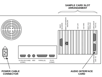
FIGURE 3.
SAMPLE BACK OF ASSEMBLED AXXESSORY TALK PC
SAMPLE CARD SLOT ARRANGEMENT
NOTE: Depending on the model of PC being used, the sample card slot arrangement and connector locations shown above could vary somewhat.
AUDIO INTERFACE CARD
2
N
D
VPC
1
S
T
VPC
POWER CABLE CONNECTOR
OP
T
ION
A
L
FA
X
C
A
R
D
MO
N
IT
O
R
CA
RD
TO
O
P
C
(P
CM
P
O
RT
)
TO
C
P
U
(P
CM
P
O
RT
)
TO PC (COM2) TO RS-232-C
(COM1)
NE
T
W
O
R
K
IN
T
E
R
F
AC
E
C
AR
D
PARALLEL KBD
FIGURE 4.
SAMPLE PC MOTHERBOARD CARD SLOT ARRANGEMENT
NOTE: Depending on the specific model of PC Motherboard being used, the sample card slot arrange-ment shown above could vary somewhat.
AUDIO INTERFACE CARD (AIC)
1ST VOICE PROCESSING CARD (VPC) OPTIONAL FAX CARD OR 3RD VPC
VIDEO CARD 2ND VPC
Fax Delivery Report Indicates Failed
Deliveries
The Fax Delivery Report now displays an asterisk (*) immediately to the left of the delivery status in the Fax Delivery Report for an entry representing a fax delivery that failed and was removed from the delivery queue. The sample Fax Delivery Report below illustrates the change. The last entry indicates a fax delivery failure.
Fax deliveries can fail for many reasons, but the most common problem is that the fax number entered was not a fax machine, but was a company’s main number or answering service. In the sample below, the failures to 1–415–345–2159 all were No Answer, probably in-dicating that the number was not a fax machine. The System Administrator should review the Fax De-livery Report on a regular basis to check for deDe-livery failures.
FAX DELIVERY REPORT Date: 4/02/1997 Delivery Date/Time Request Date/Time Delivery Status Fax Number
4–02–1997 13:44:46 4–02–1997 13:43:40 Successful 16176251201 – 8615
4–02–1997 13:52:14 4–02–1997 13:51:17 No Answer 14153452159 – 218
4–02–1997 13:56:21 4–02–1997 13:55:14 Busy 15056327936 – 111
4–02–1997 14:01:35 4–02–1997 13:54:52 Successful 15056327936 – 52
– 53 – 101 – 102 – 110
4–02–1997 14:03:28 4–02–1997 13:51:17 No Answer 14153452159 – 218
4–02–1997 14:08:07 4–02–1997 13:55:14 Successful 15056327936 – 111
4–02–1997 14:13:15 4–02–1997 13:58:51 Busy 19089963039 – 61
– 60
4–02–1997 14:14:36 4–02–1997 13:51:17 No Answer 14153452159 – 218
4–02–1997 14:25:05 4–02–1997 13:51:17 No Answer 14153452159 – 218
4–02–1997 14:28:00 4–02–1997 13:58:51 Successful 19089963039 – 61
– 60
AXXESSORY Talk VisualMail
This is available in the AXXESSORY Talk NT version only. AXXESSORY Talk VisualMail is a feature that
provides the first step to linking Inter-Tel’s NT version of AXXESSORY Talk voice mail with E-mail. AX-XESSORY Talk VisualMail provides users the ability to receive a voice mail message as an E-mail message with a voice attachment. The voice attachment will be in the form of a “wave” (.wav) file that can be played on any computer equipped with a sound card, speakers, and multimedia software (such as Sound Recorder).
When a mailbox receives a voice mail message or uses the voice mail Record-A-Call feature, one of three things can occur, depending on how the mailbox’s VisualMail field is programmed.
• If the field is programmed to DISABLED, the voice mail or Record-A-Call message is delivered to the mailbox just as normal and no E-mail is sent. • If the field is programmed to FORWARD ONLY, the AXXESSORY Talk will convert the voice mail or Record-A-Call message to an 8-bit WAV file, build an E-mail message, attach the WAV file, and send the E-mail message to the address specified in the mailbox’s mail Address field. Once the E-mail message is sent, the original message will be deleted from the mailbox. (If the E-mail message cannot be delivered to the specified address, it will be stored as a voice mail message in the mailbox and will not be deleted.) NOTE: If VisualMail is programmed for FORWARD ONLY, the mailbox cannot use the Remote Notification feature. Be-cause all messages are automatically sent to the E-mail address, there is no voice E-mail message to trigger the Remote notification.
• If the mailbox’s VisualMail field is programmed to COPY & FORWARD, the voice mail or Record-A-Call message will be stored in the mailbox and the AXXESSORY Talk will convert the file to WAV, attach it to an E-mail message, and deliver the E-mail message to the address specified in the mailbox’s E-mail Address field.
NOTE: Due to the nature of network connections, the AXXESSORY Talk software is designed to handle a network failure gracefully. If the network link from the AXXESSORY Talk to the E-mail server is down, AX-XESSORY Talk will store the messages in a queue. If the network does not come back up in 15 minutes, the AXXESSORY Talk will deliver all pending messages in the queue back to the voice mailboxes and tempo-rarily disable the E-mail queue until the network is
available. This means that new messages will remain in the mailboxes and will not be converted to E-mail mes-sages until the network link is restored.
AXXESSORY Talk VisualMail is a “one-way” feature. That is, the user cannot reply to the sender of a voice mail message using E-mail. If a user attempts to reply, the message will be sent to the Administrator’s E-mail Address instead of to the sender of the voice mail mes-sage. The user should forward the message or send a new message instead of replying.
E-mail messages containing WAV files can be for-warded to other E-mail addresses or stored on the com-puter’s local drive, just like any other E-mail message. Or, the WAV file can be detached from the message and stored on the computer.
E-mail System Requirements
To use this new feature, the customer must have an existing E-mail system based on Message Application Programming Interface (MAPI), Vendor Independent Messaging (VIM), or Simple Mail Transport Protocol/ Post Office Protocol (SMTP/POP3). The following list shows the E-mail systems that are supported, and the protocols on which they are based.
• Microsoft Mail or Microsoft Exchange (MAPI) • cc:Mail or Lotus Notes (VIM)
• Internet mail (SMTP/POP3)
NOTE: Be sure the AXXESSORY Talk PC has Win-dows NT 4.0 Service Pack 3 installed.
The AXXESSORY Talk VisualMail feature requires that the AXXESSORY Talk PC is able to communicate with the customer’s E-mail system through the custom-er’s TCP/IP network (such as a LAN). This requires a network interface card in the AXXESSORY Talk PC. Since each customer’s network can be different, the customer’s network administrator should be responsi-ble for configuring the network interface card in the AXXESSORY Talk PC as well as the network settings in Windows NT. (Note that the AXXESSORY Talk software will use TCP/IP protocol, therefore the cus-tomer’s network must support this protocol.)
System Software Keys
To use the AXXESSORY Talk VisualMail feature, you must have a software key attached to the parallel port on the AXXESSORY Talk PC. The software key also determines the number of users that can be pro-grammed to use AXXESSORY Talk VisualMail. If the key is removed, the VisualMail feature will default to five-user status. Keys are available for the following quantities of users:
NO. OF USERS PART NUMBER
5 NO KEY NEEDED
25 827.8703 50 827.8704 100 827.8705 250 827.8706 500 827.8707 1000 827.8708
A user is defined as a mailbox that has VisualMail en-abled or has a Fax E-mail Address programmed. The software compares the number of mailboxes pro-grammed for VisualMail against the user limit of the software key periodically. It then sends a message showing the number of users to Avdapmon, which can be viewed using the Avdapmon utility. Exceeding the user limit of the software key will disable VisualMail for all mailboxes. If this happens, there will be a warn-ing message in Avdapmon and an alarm at the System Administrator’s station. You must install a higher-limit software key or disable VisualMail or Fax E-mail Ad-dresses at some mailboxes to be back within the user limit. When you are within the limit, VisualMail will restart automatically.
WAV File Storage Requirements
WAV files require more storage space than Rhetorex voice files. For example, a 1MB voice mail message will require 2.67MB as a WAV file. Here are some sample file sizes for comparison:
DURATION OF MSG IN SECONDS
VOICE MAIL FILE SIZE IN BYTES
WAV FILE SIZE IN BYTES
30 89,640 239,148
60 180,480 481,324
90 269,568 718,892
120 361,536 964,140
600 1,801,056 4,802,860
Because the WAV files are stored on the customer’s E-mail server, the customer’s network administrator is
responsible for allotting sufficient space for the mes-sages.
E-mail Message Format
The E-mail message sent by the voice mail will have the following components:
• To: The TO line will contain the recipient’s E-mail address.
• From: The FROM line will contain the E-mail ad-dress of the AXXESSORY Talk. If an E-mail Real Name has been programmed for the AXXESSO-RY Talk, it will also be shown on this line. • Subject: The SUBJECT line will contain the line
“<length of message> Message for MB <number> from <source>.” If the message is marked prior-ity, the subject line will be preceded by the word “PRIORITY.” The source of the voice mail mes-sage will appear as one of the following: — MB <number>
— x <extension number> — the voice mail system — an unknown caller
— an outside caller at <phone number>
NOTE: If the message is from an extension ID or a mailbox, the programmed username will be shown inside parentheses after the number. For example: mailbox 1000 (ADMIN).
• Received on: The RECEIVED ON line contains the date and time that the voice mail was received by the mailbox.
• Priority, Private, or Certified: If the voice mail message was sent with a delivery option, the body will contain the line “Message marked
<PRIOR-ITY, PRIVATE or CERTIFIED>.” Note that this is
for informational purposes only and does not affect on the E-mail message itself. For example, if a voice mail message is marked for certified deliv-ery, the sender will receive a confirmation when the recipient listens to the voice mail message us-ing the mailbox. However, the sender will not re-ceive confirmation when the recipient reads the E-mail.
Programming
AXXESSORY Talk VisualMail must be programmed on the system-wide level and the mailbox level. It can-not be programmed through the AXXESSORY Talk mailboxes.
System-wide programming is performed through the AXXESSORY Talk System-Wide Information screen, as shown on the next page. After the system-wide E-mail fields have been programmed and saved to the database, the AXXESSORY Talk will log on to the cus-tomer’s E-mail system. At that point, it is ready to start sending E-mail messages.
NOTE: The installer should watch the voice mail mon-itor closely and examine the AXXESSORY Talk mes-sages to make sure that VisualMail is started. If it does not start, the AXXESSORY Talk will keep trying every 30 seconds until login is successful or VisualMail is manually disabled.
Next, each mailbox that is going to use the AXXESSO-RY Talk VisualMail feature must be configured. This requires programming of the mailbox’s VisualMail and E-mail Address fields. Once these fields are
pro-grammed, AXXESSORY Talk VisualMail is fully op-erational. Mailbox programming is performed using the Mailbox screen shown on page 30.
Note that there are some other external configurations involved in getting the AXXESSORY Talk VisualMail to work:
• The network interface card installed in the AX-XESSORY Talk PC must be configured properly. • Windows NT networking must be properly
config-ured for the customer’s network configuration. • The customer’s E-mail System that is used by
AX-XESSORY Talk VisualMail should be tested to send and receive E-mail properly.
The installer/programmer should test the AXXESSO-RY Talk to make sure that:
• All E-mail addresses are programmed correctly. • E-mail messages are sent to the E-mail server
suc-cessfully.
↓NEW VISUALMAIL PROGRAMMING FIELDS↓
NEW BUTTON→ ←NEW BUTTON
System-wide AXXESSORY Talk VisualMail fields cannot be programmed if you enter the database using the “User” password. The programming fields are as follows:
E-MAIL SYSTEM: This system-wide field specifies the type of E-mail system that will be used to transfer messages. The value programmed in this field must correspond to the customer’s underlying E-mail sys-tem. For example, if the customer’s E-mail system is Lotus Notes, this field should be programmed to VIM. This field can be programmed to NONE, MAPI, VIM, or SMTP/POP3. If it is programmed to NONE, the AX-XESSORY Talk VisualMail feature is disabled for the entire voice mail system. The default value for this field is NONE.
E-MAIL SETTINGS: After you have selected the E-mail System, the E-mail Settings command button is available. When you select it, the window shown on the next page appears. The fields that need to be pro-grammed depend on the E-mail System selected:
• If the E-mail System field is programmed to MAPI or VIM, only the E-mail Username and E-mail Password fields need to be programmed.
• If the E-mail System is programmed to SMTP/ POP3, the E-mail SMTP Server and E-mail Ad-dress fields must also be programmed, in addition
to the username and password fields. The E-mail Real Name field is optional when using SMTP/ POP3.
NETWORK SETTINGS: For VisualMail to function, the “Avdap” service must be able to log on to the net-work as a user. To program the logon information (net-work domain, username, and password), select the Net-work Settings command button. A window appears as shown on page 29.
E-MAIL ADDRESS: This field specifies the AXXES-SORY Talk’s E-mail address. It is only required if the E-mail System field is programmed to SMTP/POP3. When the voice mail PC sends an Internet mail mes-sage, this address will be used as the E-mail address in the “Reply-To” field of the E-mail header. This is the address at which the voice mail PC will receive Internet mail messages. This field can contain up to 127 charac-ters and it is empty by default. For example, when using Internet mail, this field might look like johndoe@inter-tel.com.
E-MAIL REAL NAME: This field specifies the AX-XESSORY Talk’s user name (such as VOICE MAIL). It is only programmable if the E-mail System field is programmed to SMTP/POP3 and it is optional. When the voice mail PC sends an Internet mail message, this name will be included in the FROM field of the E-mail header. This field can contain up to 127 characters, and it is empty by default.
E-MAIL USERNAME: This field specifies the user-name for the voice mail PC’s E-mail account. Before the voice mail PC can send or receive E-mail messages, it must log on to the underlying E-mail system. There-fore, the voice mail PC must have an account on the customer’s E-mail system, and this field specifies the username for that account. This field can contain up to 127 characters and it is empty by default.
E-MAIL SMTP SERVER: This field specifies the AXXESSORY Talk’s SMTP mail server. It is only pro-grammable if the E-mail System field is programmed to SMTP/POP3. The SMTP mail server is the server that the voice mail PC connects to in order to send
E-mail messages over the Internet. This field can con-tain up to 127 characters and it is empty by default.
E-MAIL POP SERVER: This field specifies the POP mail server that will be used to receive E-mail mes-sages. It is only programmable if the E-mail System field is programmed to SMTP/POP3. The POP mail server is the server the voice mail PC connects to in order to send E-mail messages through the Internet. This field can contain up to 127 characters and it is empty by default.
ADMINISTRATOR E-MAIL ADDRESS: This field specifies the E-mail address of the System Administra-tor. Whenever an E-mail message is undeliverable (due to invalid or wrong E-mail address, etc.) it will be for-warded to this address. Or, if a user attempts to reply to a VisualMail E-mail message, the message will go to this address instead of going to the AXXESSORY Talk PC. This field can contain up to 127 characters and it is empty by default. NOTE: Even though this field is not required, Inter-Tel strongly recommends that you pro-vide an E-mail address to forward any E-mail received by the AXXESSORY Talk PC. It will alert the Admin-istrator to any problem with the E-mail addresses.
The following information is used by the Avdap service when it logs on to the network. Refer to page 18 for information about setting up the Avdap user account. NETWORK DOMAIN: This field specifies the name of the network domain in which the AXXESSORY Talk PC is a member.
USERNAME ON NETWORK DOMAIN: This field specifies the username that the Avdap service user ac-count will use to log on to the network.