Removal of Impulse Noise from Remote
Sensing Images Using Wavelets Based on
Image Fusion Algorithm
T. Ajay1, G. Anand Kumar2
M.Tech [CSP], Dept. of ECE, GVP College of Engineering (A), Visakhapatnam, Andhra Pradesh, India1.
Assistant professor, Dept. of ECE, GVP College of Engineering (A), Visakhapatnam, Andhra Pradesh, India2
ABSTRACT: Remote sensing plays a prominent role in many domains related to the observation of the earth such as agriculture monitoring, military battles, land cover, oceanography etc. The multiple sensors are used for capturing the images in remote sensing applications. In remote sensing applications the sensor output images are mainly affected by Impulse noise. This impulse noise can be removed by using various filtering methods. In this paper Image fusion is used for combining multiple sensor images into single image. The resultant image can be de-noised by using wavelets filtering algorithm. The performance evaluation of the filtered and fused image with respect to the original image is calculated by using Peak signal to noise ratio (PSNR).
KEY WORDS: Remote sensing, noise, wavelets, image fusion, DWT.
I. INTRODUCTION
Noise is unwanted information that corrupts an image. There are various sources of noise. In remote sensing applications multiple sensors are used for capturing the images. Depending on the propinquity to the object, sensor features and environmental disturbances these images are affected by noise. The image is contaminated by different types of noise depending on the sensor application and hardware. In image processing uniform noise, impulse noise, Gaussian noise, gamma noise and exponential noise are the prominent noise models which effect the image. In this paper the main aim is to remove the effect of impulse noise from remote sensing images which are captured by multiple sensors.
In most of the remote sensing images, the images from different sensors are combined to form a single image, which retains the prominent features of images from each sensor individually. The process is called as Image Fusion [1]. In this paper, the noised images from multiple sensors can be combined into a single image by using Fusion algorithm. The Impulse noise that effects the fused image can be removed by using Wavelet transform technique.
II. LITERATURE SURVEY
Algorithms for the removal of Impulse noise using filters and image fusion techniques are existing in the literature. During the years many algorithms have developed for the reduction of impulse noise and for image fusion technique, a few of them are M. Jaya Manmadha Rao [1] proposed an algorithm Image Fusion Algorithm for Impulse Noise Reduction in Digital Images. L Ganesh [2] proposed an algorithm Development of Image Fusion Algorithm for Impulse Noise Removal in Digital Images using the quality Assessment in Spatial Domain. Salem Saleh Al-amri [3] proposed an algorithm A Comparative Study of Removal Noise from Remote Sensing Image. Sachin D Ruikar [4] proposed an algorithm Wavelet Based Image De-noising Technique. Reeta Charde [5] proposed an algorithm Performance Comparison of Wavelet De-noising and Median Filter De-noising over AWGN Channel.
images, may be effected by impulse noise. In this paper, the noise can be detected from every sensored images individually by calculating the noise density. After detecting the noise the noised images can be filtered by using pixel restoration median filter individually. Finally, all the filtered images are combined into a single image using fusion algorithm. The fused image is more reliable than the input images.
III. PRELIMINERIS
(A) Impulse Noise: Digital images are prominently effected by Impulse noise. Impulse noise [1] [2] is uncorrelated and is independent to the image pixels; it is distributed randomly over the image. Unlike Gaussian noise effected images, Impulse noise images all the image pixels are not completely noisy, some will be effected by noise and remaining will be noise less or noise free. The impulse noise is categorized as two types namely Salt and Pepper noise and Random valued impulse noise.
In Salt and Pepper type noised image, the noise pixels takes the values either salt value which is having gray level -225 or Pepper value having gray level-0. The salt and pepper type noise appears as white and black spots on the images. In the case of Random valued impulse noise, the pixels contaminated by noise can takes any gray level values from 0 to 225. In this type also, noise is distributed randomly over entire the image and there will be equi-probable occurrence of any gray level value as noise.
(B) Wavelets: Wavelet is a transform technique is used for Image compression, signal processing, pattern recognition and De-noising. A ‘wavelet’ is a small wave having oscillating wave like characteristics with its energy concentrated in time & it as time-scale and time-frequency analysis tools have been extensively used in topographic reconstruction and still mounting. Wavelets are generated from a single basis function ψ(t) called mother wavelet by means of scaling and translation:
, ( ) = | |
−
; , ⋲ , ≠ .
where s is the scaling parameter and τ is the translation parameter. Wavelets must have zero mean and have band pass like spectrum. Wavelets are of two types continuous wavelet transform (CWT) and Discrete wavelet transform (DWT).
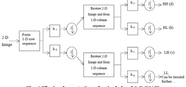
The DWT is extensively used in its non-redundant form as standard DWT. The standard DWT implemented for images using filter bank is viewed in two dimensions known as 2-D DWT [3]. Two-dimensional implementation of wavelet transform is required for Image-processing applications. The Implementation of 2-D DWT is also called as ‘multidimensional’ wavelet transform. The analysis filter bank for the implementation of a single level 2-D DWT is shown in figure.
Fig. 1 The implementation of a single level 2-D DWT
channel in a similar manner. This process provides a multilevel decomposition [4]. The structure of multilevel decomposition of an image is shown in figure.
Fig. 2 Multilevel decomposition of an image with 2-D DWT
(C) Image Fusion:
Multi sensor data is available in many fields like remote sensing, machine vision, medical imaging and military applications etc. because of which sensor fusion has emerged as a new and potential research area. The main goal of Image Fusion is to form a new image that contains more reliable information which is used for the purpose of human visual perception, target recognition and object detection.
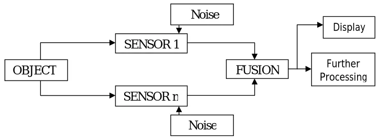
Image Fusion is referred to a process of combining two or more images from multiple sensors to form a single composite image that contains more reliable information. A simple diagram of a system using pixel-level image fusion [5] is shown in the block diagram in figure below.
Fig. 3 Block diagram of Image Fusion
In remote sensing applications a single object can be captured by multiple sensors. These sensor images may contain an impulse noise. In fusion algorithm, split the image captured by individual sensors into 8X8 non-overlapping blocks. Calculate the variance for every block. Based on the variance value, the block which is having the least variance value that block will be reconstructed into the fused image. This process is continued for all the non-overlapping blocks for all the input images and forms a fused image.
SENSOR 1
SENSOR n
FUSION
OBJECT
FurtherProcessing
Noise
Noise
IV. PROPOSED METHOD
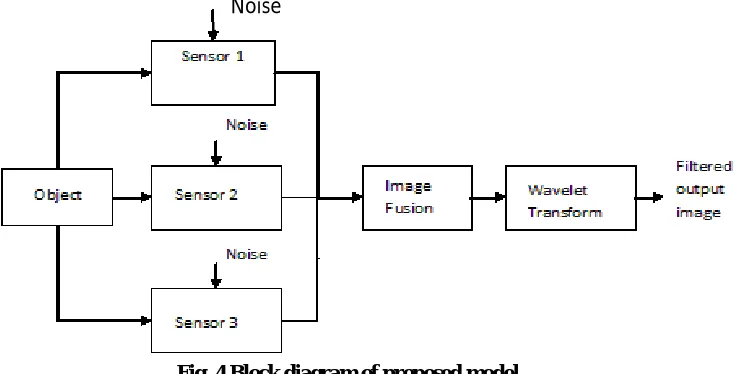
This paper proposes a method for the removal of impulse noise using wavelets. In this proposed method, first all the images from different sensors can be fused into a single image. After fusing the images, the noise can be removed by using wavelets. The Discrete wavelet transform is used for de-noising purpose. The block diagram for the proposed method is shown in fig.
Fig. 4 Block diagram of proposed model
Algorithm for the removal of Impulse noise using Wavelets:
Step 1: Consider the fused image as input image for the wavelet decomposition Step 2: Split the image into RGB planes
Step 3: Decompose each plane using 2D-DWT; the decomposed image consists of four sub bands LL, LH, HL, and HH.
Step 4: Consider a 3x3 mask, center of the mask is placed in the present pixel
Step 5: The edges in the sub-band are calculated using the center pixel and neighboring pixels by using the formula Gray level Difference (GD) = ∑ ∑ | (0,0)− ( , )| where (i, j) ≠ (0, 0)
Step 6: Step 2 treats edges and noise present in an image as noise. So edges of the image should be removed by using Average Background Difference (ABD).
Step 7: Noise in the image can be calculated by using ABD.
ABD = (0,0)−( ∑ ∑ ( , ))/8 , where (i, j) ≠ (0, 0)
Step 8: The pixel values containing noise are removed by taking 3x3 mask which gives the mean of neighboring pixels based on the threshold values obtained from GD and ABD
Step 9: Perform Thresholding on each sub band of the decomposed image Step 10: Apply IDWT for the four sub bands.
V. EXPERIMENTAL RESULTS
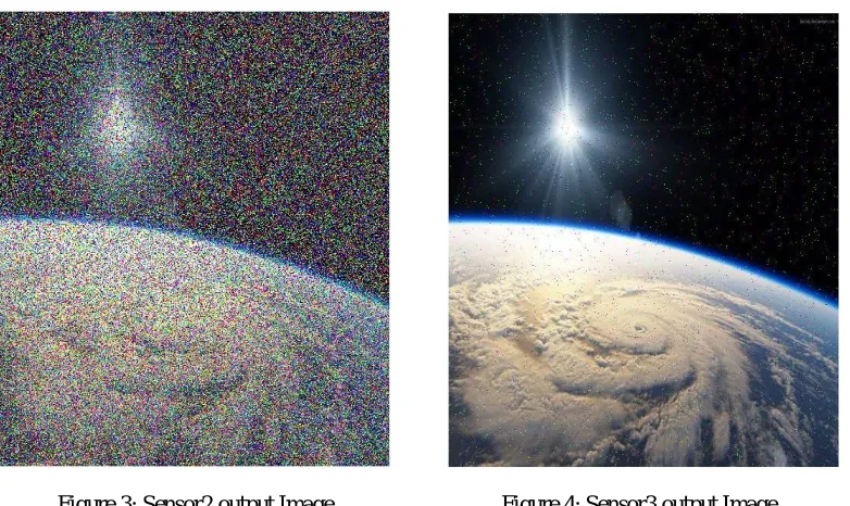
In this paper, consider an input image which is shown in Figure1. This image is captured by different sensors. For this example, three sensors are considered. The sensor output images with adding Impulse noise having different noise densities are shown in Figure2, Figure3, and Figure4 respectively. The three sensor images are combined to form a fused image which is shown in Figure5. The fused image is filtered by using wavelet transform. The filtered output is shown in Figure6.
Figure1: Original Image Figure 2: Sensor1 output Image
The Fig 1 is the original satellite image and fig 2 represents sensor 1 output image which is contaminated by 5% of impulse noise.
Figure 3: Sensor2 output Image Figure 4: Sensor3 output Image
Figure 5: Fused Image Figure 6: Wavelet Filtered output Image
Fig 5 represents Fused image, it is formed by combination the three sensors output images. Fig 6 represents the filtered output image using Wavelet. Finally, the performance of all the sensor output images, fused image and filtered image can be evaluated using PSNR with respect to the original input image. The performance of the fused and filtered image by using PSNR values is shown in Table.
S.NO Output PSNR (in dB)
1 Sensor1image 9.4742
2 Sensor2 image 2.5101
3 Sensor3 image 19.5999
4 Fused image 19.7850
5 Wavelet filtered Image 28.4193
Table 1: Performance evaluation of images using PSNR values
From the results shown, it can be cleared that the fused image has high PSNR value when compared with all the sensor output images individually and Filtered output image has high PSNR value compared with the Fused image.
VI. CONCLUSION
image. The Wavelet Filtering method reduced the noise up to 10dB when compared with the fused image, where as compared with all the sensor output images the noise is reduced from 9dB to 20 dB approximately.
REFERENCES
1. M. Jaya Manmadha Rao, Dr.K.V.V.S.Reddy, “Image Fusion Algorithm for Impulse Noise Reduction in Digital Images”, Global Journal of Computer Science and Technology Volume 11, Issue 12 Version 1.0, July 2011.
2. L Ganesh, S P Krishna Chaitanya, J Durga Rao and M N V S S Kumar, “Development of Image Fusion Algorithm for Impulse Noise Removal in Digital Images using the quality Assessment in Spatial Domain”, International Journal of Engineering Research and Applications (IJERA) Vol. 1, Issue 3, pp.786-792.
3. Reeta Charde, “ Performance Comparison of Wavelet Denoising and Median Filter Denoising over AWGN Channel”, International Journal of Engineering Research & Technology (IJERT) Vol. 1 Issue 5, July – 2012.
4. Burhan Ergen, “Signal and Image Denoising Using Wavelet Transform”, Fırat University,Turkey.
5. Sachin D Ruikar and Dharmpal D Doye, “Wavelet Based Image Denoising Technique”, (IJACSA) International Journal of Advanced Computer Science and Applications, Vol. 2, No.3, March 2011.
6. Chang, S. G., Yu, B., and Vetterli, M. (2000), “Adaptive wavelet thresholding for image denoising and compression”, IEEE Trans. On Image Proc., 9, 1532–1546.