Storage Technology Corporation
2920
Tape
Subsystem
Maintenance Manual
Information contained in this publication is subject to change. In the event of changes, the publication will be revised. Comments concerning the contents of this manual should be directed to Tape/Disk Tecl:mical Publications at the address below. A prepaid Reader's Comment Form is provided at the back of the manual.
This publication was prepared by Storage Technology Corporation, Tape/Disk Technical Publications, MD 97, 2270 . South 88th Street, Louisville, Colorado 80028.
Warning; For the purpose of designing a system that complieS with FCC Rules and Regulations, Volume II, Part 15, Subpart J, this product is considered to be a component within the total system configuration. It is the customer's responsibility to take such action as necessary (shielded cabling, cabinet considerations, etc.) while integrating this product into his system so as to comply with the above ruies. Contact Storage Technology Corporation for technical assistance in this matter.
Copyright © 1984 by
LIST OF EFFECTIVE PAGES
Publication PN 95521
Issue Date: August 1983 EC 49546
Reissue Date: October 1984 EC 49717 KIT PN 97772
Total number of pages in this document is 260, consisting of the following pages:
Page
Tit le Copyright
i i i thru XX 1-1 thru 1-12 2-1 thru 2-22 3-1 thru 3-20 4-1 thru 4-38 5-1 thru 5-30 6-1 thru 6-16 7-1 thru 7-12 8- 1 thru 8- 30 9-1 thru 9-20 A-1 thru A-2 B-1 thru B-8 C';'l thru C-6 D-1 thru D-6 E-1 thru E-6 Index 1 thru 8
Reader's Comment Form Business Reply Mailer
EC No.
49717 49717 49717 • 49717 49717 49717 49717 49717 49717 49717 49717 49717 49717 49717 49717 49717 49717 49717 None None
Kit PN
97772 97772 97772 97772 97772 97772 97772 97772, 97772 "97772 97772 97772 97772 97772 97772 97772 97772 97772' " '.' None"
None,
~ . , '
Disposition
TABLE OF CONTENTS
Paragraph Title
CHAPTER 1 GENERAL INFORMATION
1.1 1.2 1 ,2, 1 1 ,2.2 1 ,2.3 1 .2.4 1.2.5 1.3 1 ,3. 1 1 .3,2
1 .3.3
Introduction . . . . General Description. Power Features . . Interface Features Mounting Options . Diagnostic Features Electronics . . . . Specifications . . . .
Physical Dimensions . . .
Environmental Requirements Power Requi rements . . . .
CHAPTER 2 OPERATION
2. 1 2.2 2.3 2.4 2.4.1 2.4.2 2.4.3 2.4.4 2.4.5 2.4.6 2.4.7 2.4.8 2.4.9 2.4.10 2.4. 11 2.4.12 2.5 2.5.1 2.5.2 2.5.3 2.5.4 2.5.5 2.5.6 2.5.7 2.6 2.6.1
Introduction .
Power On/Off Switch
Display . .
Operator Functions Area . Ready Indicator (Green) Se 1 ect Indi ca tor (Ye llow) EDT/BOT Indicator (Green) On Line Indicator (Green) Machine Check Indicator (Red)
File Protect Indicator (Red) . System Select/1600/6250 Indicators
(Yellow)
Density Select Key Rewind/Unload Key Reset Key
Load/Rewind Key On Line Key
Diagnostic Keypad .
Enter Address Key Display Address Key Modify Memory Key Enter Probe Key
Enter Diagnostic Key
Enter Key . . .
Clear Key . . . .
Tape Threading Operations . . . . Automatic Thread/Load--Vertical Mount
Page
1 - 1 1 - 1 1-7 1 -7 1-7 1-7 1 -7 1-10 1-10 1-10
1 - 11
'Paragraph 2.6.2 2.6.3 2.6.4 2.6.5 2.6'.6 2.6.7 2.7 2.7.1 2.7.2 2.7.3 2.7.4 2.7.5 2.8 2.8.1 2.8.2 2.9 2.10 2. 11 2.12 2.13 2.14
TABLE OF CONTENTS CONT
Title
SemiAutomatic Thread/Load-Vertical Mount . SemiAutomatic Thread/Load--Center of
Gravity Mount . . . . Manual Thread/Load--Vertical or Center
of Gravity Mount . . . .
Midtape Load, EDT Area . . . . . . .
Rewind . . . . . , . . Unload . . . . . . . .
Opera tor Ma i ntenance . . . . . . . . Read/Write Head and Tape Cleaner Block EDT/BOT and Leader Sensors . . .
Tape Guides, Rollers, and Swing Arms. Capstan . . . .
File Reel Hub . . . .
Tape Motion Characteristics . . . . . . . Start/Stop Mode . , . . . .
Streaming Mode . . . . InterblocK Gap (IBG) Generation '. Reposition Timing . . .
Reinstruct Times
50/100 ips Speed Change . Turnaround Delays
Duty Cyc le·· . . . . CHAPTER 3 INST ALLA TION
3. 1 Introduction
·
·
..
·
·
· ·
·
·
3.2 Inspection
.
·
· ·
·
·
3.3 Power Connection
·
·
·
· · ·
3.4 Pre 1 im; nary .ChecKout
.
· ·
·
· · ·
3.5 Vertical Cab; net Mount i ng . . .· ·
·
· ·
·
3.6 Center of Gravity (Horizontal) CabinetMount
. . . · ·
i : I I : , I· · · ·
3.7 StorageteK Standard Interface Cabling
·
3.8 Industry Standard Interface Cabling· · · ·
3.9 Address Selection
·
·
· ·
3.10 Reshipping
· · · . · · · ·
CHAPTER 4 STORAGE TECHNOLOGY STANDARD INTERFACE
4,1 4.2 4.2.1
Introduct ion . . . . Inp!Jt Line Defin; tions . .
MTS Address (ADO, AD1)
Paragraph 4.2.2 4.2.3 4.2.4 4.2.5 4.2.6 4.2.7 4.2.8 4.2.9 4.3 4.3.1 4.3.2 4.3.3 4.3.4 4.3.5 4.3.6 4.3.7 4.3.8 4.3.9 4.3.10 4.3. 11 4.3.12 4.3.13 4.3.14 4.3.15 4.3.15.1 4.3.15.2 4.3.15.3 4.3.15.4 4.3.16 4.3.17 4.3.18 4.3.19 4.3.20 4.3.21 4.3.22 4.3.23 4.3.24 4.3.25 4.4 4.4.1 4.4.1.1 4.4.1.2 4.4.1.3 4.4.1.4 4.4.1.5
TABLE OF CONTENTS
CO NT
Title
Initiate Command (START) . . . . Command Select (CMDO, CMD1, CMD2, CMD3) Density Select (DSO, DS1) . . . . . Transfer Acknowledge (TRAK) . . . . Terminate Command (STOP) . . . .
System Reset (RESET) . .
Select Multiplex (SLXO, SLX1, SLX2) Bi-Directional Data (DATA 0-7,P) Output Line Definitions.. . . .
Transfer Request (TREQ) . . . Expecting Data (RECV)
Block Sensed (BLOCK) .
Oscillator (OSC) . . . End of Data Pulse (ENDATP) Busy (BUSY) . . . . Identification Burst (ID BRST) . Tape Mark Status (TMS) . . . Command REJECT (REJECT) . Operation Incomplete (OP INC) Overrun Status (OVRNS) . . . EPROM Error (ROMPS) . . . . . Slave Status Change (SSC)
Da ta Check (DATA CHK) . . . Error Multiplex (ERRMX 0-7,P)
Mux Byte 0 . . . Mux Byte 1 . . . . Mux Byte 2 . . . MUX Byte 3 .
Corrected Error (CRERR) . . Data Bus Parity Error (BUPER) Online Status (ONLS) . . . . . Ready Status (RDYS) . . . .
Beginning of Tape Status (BOTS) . . . End of Tape Status (EOTS) . .
File Protect Status (FPTS) . Write Status (WRTS)
High Density Status (HDNS)
Rewinding Status (REWS) . .
Functional Mode Command Descriptions . . . .
General Information . . . . . . .
Command Initiation . . . . .
REJECT Conditions . . . .
Operation Completed . . . . Ending Status Validity .
End of Tape Status (EOTS)
Paragraph 4.4.1.6 4.4.1. 7 4.4.2 4.4.3 4.4.4 4.4.4.1 4.4.4.2 4.4.4.3 4.4.4.4 4.4.4.5 4.4.4.6 4.4.4.7 4.4.4.7.1 4.4.4.7.2 4.4.5 4.4.5.1 4.4.5.2 4.4.5.3 4.4.6 4.4.6,1 4.4.6.2 4.4.7 4.4.7.1 4.4.7.2 4.4.8 4.4.9 4.4.9.1 4.4.10 4.4.10.1 4.4.10.2 4.4.10.3 4.4.11 4.4.11.1 4.4.12 4.4.12.1
TABLE OF CONTENTS
CO NT
Title
Commands with MTS in Write Status Improper Command Sequences . . . No Operation (NOP) Command (0000)
Drive Clear (CLR) Command (0001) . .
Diagnostic Mode Set (DMS) Command (0010) . DMS/NOP (Status Lines Test Command) DMS/WRT (SLX 2,1,0
= 000) (Write In
Place Command) . . .
DMS/WRT (SLX 2,1,0
= 001) (Write No
Motion Command) . .DMS/RDF (SLX 2,1,0
= 000) (Read No
Mot ion Command) . . . .
DMS/WRT (SLX 2,1,0
=
111) (FunctionalSpeed/Gap Select) . . .
DMS/FSF (SLX 2,1,0,= 000) (Perform Loaded Di agnost ics) . . , . DMS/FSB (SLX 2,1,0
= 000) (Perform
All Diagnostics) . . . . DSB5 and DSB6 Description
DSB8 Through DSB55 Description . Read Forward. a Block (RDF) Command
(0100) . . . . . .
Signal Sequ~nce . . .
RDF/BOT. . . . . . . . .
RDF /Tape Mark BlocKs . . .
Read BacKward a BlocK (RDB) Command
(0101) . . . .
RDB/BOT . . . . . . .
RDB/Tape MarK Blocks . . . .
Write a Data Block (WRT) Command (0110)
Signa 1 Sequence . . . . ,
WRT/BOT. . . . . . . . , . .
Loop Write-to-Read (LWR) Command (0111) BacKspace a File (BSF) Command (1000)
BSF /BOT . . . . . . . Backspace a BlocK (BSB) Command (1001)
Signal Sequence. . .
BSB/BOT . . . .
BSB/Tape Mark . . . . .
Forward Space a File (FSF) Command
(1010) . . . . . .
FSF/BOT . . , . . . . .
Forward Space a Block (FSB) Command
(1011) . . , . . . , , . , '
Signal Sequence. . . .
Paragraph 4.4.12.2 4.4.12.3 4.4.13 4.4.13.1 4,4.14 4.4.14.1 4.4.15 4.4.15.1 4,4.16 4.4.16.1 4.4.17 4.4.17.1 4.4.17.2
TABLE OF CONTENTS CONT
FSB/BOT . . . . FSB/Tape Mark . . . . Write Tape Mark (WTM) Command (1100) .
WTM/BOT . . . .
Erase Gap (ERG) Command (1101) . . . ERG/BOT . . . . R ew ; nd (R E W ) Command (1 11 0 ) . . . .
REW/BOT . . . , . . Rewi nd and Un load (RUN) Conmand (1.111)
RUN/BOT . . . .
Sense Drive Status (SNS) Conmand (0011) Signal Sequence . . .
Sense Bytes Description .
CHAPTER 5 INDUSTRY STANDARD INTERFACE
5. 1 5.2 5.2.1 5,2.2 5.2.3 5.2.4 5.2.5 5.2.6 5.2.7 5.2.8 5.2.9 5.2.10 5.3 5.3.1 5,3,2 5.3.3 5.3.4 5.3.5 5.3.6 5.3.7 5.3.8 5.3.9 5.3.10 5.3.11 5.3.12
Introc:luct ion . . . . Input Line Definitions . . . .
MTS Address (FFAD, FTADO, FTAD1) Initiate Command (FGo) .
Rewi nd To BOT (FREW) . . . . . . Command Offline (FoFL) . . . .
Formatter Enable (FFEN)
Last Word (FLWD) . . . .
Write Data Lines (FWDO-7,p) . . . High Speed Select (FHISP) (2922 devices
only) . , . . . . fI •
Long Gap Select (FLGAP) (2922 devices
only) . . . . I • • • • • • • • • • I
Conmand Select Lines (CMDO, 1, 2, 3, and
4) • • . • . • • . • . • .
Output Signal Definitions . .
Formatter Busy (FFBY) . . .
Da ta Busy (FDBY) . . . . . . . . . Identification Burst (FID) . . .
Hard Error (FHER) .
File Mark Detected (FFMK) Corrected Error (FCER) Ready (FRDY) . . . . Online (FoNL) . . Rewind (FRWD)
End Of Tape (FEOT) . File Protect (FFPT) Load Point (FLDP)
Paragraph 5.3.13 5.3.14 5.3.15 5.3.15.1 5.3.15.2 5.3.16 5.3.16.1 5.3.16.2 5.3.17 5.4 5.4.1 5.4.2 5.4.3 5.4.4 5.4.5 5.4.6 5.4.7 5.4.8 5.4.9 5.4.10 5.4.11 5.4.12 5.4.13 5.4.14 5.4.15 5.5 5.5.1 5.5.2 5.5.3 5.5.4 5.5.4.1 5.5.4.2 5.5.5 5.5.6 5.5.7 5.6 5.6.1 5.6.1.1 5.6.1 .2
TABLE OF CONTENTS CONT
Tit le
High Speed Streaming (FHSPD) . . . High Density Status (GCR) . . : . Demand Write Data Strobe (FDWDS) . .
FDWDS Timing, 50 IPS Operations FDWDS Timing, 100 IPS Operations
Read Data Strobe (FRSTR). . .
FRSTR Timing, 50 IPS Operation . . FRSTR Timing, 100 IPS Operation
Read Data Lines '0-7,p (FRDO-7, p) . . Command Lines Decodes - Functional Commands
Description . . . . . . . . . Read Forward Command (00000) . .
Read Reverse Command (01000) .
Write Command (00100) . . . .
Write File Mark Command (00110) Write Extended Command (01110) Fixed Erase Command (00111)
Controlled Erase Command (00101) . . Data Security Erase Command (10111) Space Forward Command (00001)
Space Reverse Command (01001)
File Search Forward Command (Ignore
Data) (00011) . . . . . . . .
File Search Reverse Command (Ignore Data) (01011) . . . . . .
Select PE Command (10011) . . . . . Se 1 ec t GC R Command (1 1 0 11) . . . . .
Read Sense Command (1100'1) . . .
Detailed Functional Sense Bytes Description Sense Byte 0 (Faults. Mode And Not
Ready). ... . .
Sense Byte 1 (Last Command Issued) Sense Byte 2 (Tape Status) . . . . Sense Bytes 3 And 4 (Hard Errors)
Sense Byte 3 . . .
Sense Byte 4
Sense Byte 5 (Reject Status) . . . Sense Byte 6 (Corrected Error And Dead
Track P) .
Sense Byte 7 (Dead TracK register)
Command Lines Decodes - Diagnostic Commands
Descr i p t i on . . .
Invoke Diagnostics (01100) . .
Run Diagnostic Package (Byte 1
= 01)
Run Loaded Diagnostics (Byte 1=
02)Paragraph 5.6.2 5.6.3 5.6.4 5.6.5 5.6.6 5.7 5.7.1 5.7.2 5.7.3
TABLE OF CONTENTS CONT
Title
Loop Write to Read (01111) . . . . Initiate Status Sequencer (10000) Command to Status Wrap (10001) . . Data Loopback (1111) . . . .
Read Extended Sense (11101) . . .
Detailed Diagnostic Sense Bytes Description DSBO and DSBl Description
DSB2 and DSB3 Description
DSB8 Through DSB55 Description ,
CHAPTER 6 FUNCTIONAL DESCRIPTION
6, 1 6.2 6.3 6.4 6.5 6.6 6.6.1 6.6.2 6.7 6.8
Introduction . . . .
Interface/Microprocessor (IF Card) Write Data Path (DP Card). . . . Write Drivers (WR Card) .
Read (RD Card) . . . Read Data Path (DP Card)
PE Operation . . . . GCR Operation . . . . Servo System (SV Card) Power System . . . . .
CHAPTER 7 MAINTENANCE
7, 1 7.2 7.3 7.4 7.4.1 7.4.2 7.5 7.6 7.7
r-ntroduct ion . . . . Quarterly Preventive Maintenance Checklist Quarterly Power Supply Check . . . . Tape Tracking and Skew Adjustment after
parts replacement . . . . Capstan Alignment (Tape Tracking) . Head Skew Adjustment . . . , Quarterly Tape Skew Checks . . . , , . , Bit Position Check After Part Replacement Quarterly Read Amplitude Checks . . .
CHAPTER 8 REMOVAL AND REPLACEMENT
8.1 8. 1 . 1 8.1 .2
8.2
Introduction Fuses
Torx Screws Tape Path . . .
Page 5-25 5-25 5-26 5-27 5-27 5-28 5-28 5-28 5-28 6-1 6-1 6-4 6-6 6-6 6-9 6-9 6-11 6-12 6-15 7-1 7-1 7-2 7-2 7-3 7-5 7-9 7-10
7 - 11
Paragraph
8 ~ 2, 1 8.2.2 8.2.3 8.2.4 8.2.5 8.3 8.3,1 8.3.2 8.3,3 8.3.4 8.3.5 8.4 8.4.1 804,2 8,4,3 8.4.4 8.4.5 8.5 8.5. 1 8.5.2 8.5.3 . 8.5.4 8.5.5 8.6 8.6.1 8.6.2 8.6.3 8.6.4 8.7 8.7,1 8.7.2 8.7.3 8.7.4
TABLE OF CONTENTS
CO NT
Title
EDT/BOT Sensor Replacement Leader Sensor Replacement
Tape Cleaner Block Replacement . File Protect Sensor Replacement Read/Write Head Replacement
Swing Arms . . . . Lower Swing Arm Assembly Replacement Lower Swing Arm Tach Assembly
Replacement . . . . . . . . Upper Swing Arm Assembly Replacement Upper Swing Arm Tach Assembly
Replacement . . . . Retractor Assembly Replacement Capstan, Reels, and Blower
Capstan Motor Replacement File Reel Hub Replacement
File Reel Motor Replacement .
Machine Reel Motor Replacement . . . . Vacuum Blower Replacement
Circuit Cards . . . . Card Cage Circuit Cards Replacement Front Operator Panel Replacement AK Card Replacement
PK Card Replacement . . . . Motherboard Replacement
Power Supply and Fans . . . . Regulator Assembly Replacement .
Transformer Replacement .
Main Circuit Breaker Replacement. Cooling Fan Replacement
Cable Harness Replacement . Cable Harness, Power . Cable Harness, AC
Cable Harness, Motor . . Cable Harness, Sensor
CHAPTER 9 DIAGNOSTIC/MAINTENANCE PROGRAMS
9, 1 9. 1 . 1 9,1.2 9.2 9.2, 1 9.2,2
Introduction . . , . , Test Initiation
Status Buffers . . . Section 0 - Maintenance
Forward Motion (00) Backward Mot ion, (01 )
Paragraph 9.2.3 9.2.4 9.2.5 9.2.6 9.2.7 9.2.8 9.2.9 9.2.10 9.2. 11 9.2.12 9.2.13 9.2.14 9.2.15 9.3 9.3.1 9.3.1.1 9.3.1 .2 9.3.1 .3 9.3.1.3.1 9.3.1.3.2 9.3.1.4 9.3.1.4.1 9.3.1.4.2 9.3.1.5 9.3.1.6 9.3.1. 7
9.3.1.8 9.3.1.9 9.3.2 9.3.2.1 9.3.2.2 9.3.2.3 9.3.2.4 9.3.2.5 9.3.2.6 9.3.2.7 9.3.2.8 9.3.2.9 9.3.2.10
TABLE OF CONTENTS
CO NT
Title
Shoeshine Motion (02) Start/Stop Motion (03) Speed Select Option (04) Continue Option (05) . . Loop Option (06) . . . . Bypass Error Option (07) Keyboard/LED Driver (08) Reel/Capstan Driver (09) Status A Display (OAI . Status B Display (OBI Status C Display (OC) Maintenance Write (OE) Maintenance Write (OF) Internal Diagnostics
Section 1 - Power-Up Tests . . Test Package Initiator (101 Memory/PROM Checksum (12) .
IF T es t 1 (1 3 I
Routine 13 for Storagetek
Interface Card .
Routine 13 for Industry Standard
Interface Card. . .
IF Test 2 (14) .
Routine 14 for Storagetek
Interface Card .
Routine 14 for Industry Standard Interface Card
Keyboard Status (15)
Servo-LSI Register Loop (18) Data Path Status (1B) . . . Write Card Status (1D)
Release/Retract Swing Arms (iF)
Section 2 - Formatter Tests .
PE
Basic Loop Write-to-Read, 50 IPS· ( 221 . , . . . .PE
LWR Velocity (23) .GCR Basic Loop Write-to-Read, 50 IPS ( 24 ) . . . .
GCR LWR Velocity (25) .
PE
LWR, One Track Dead (26) GCR LWR, One Track Dead (27)PE
LWR, Two Tracks Dead (28) GCR, LWR, Two Tracks Dead (29)PE
Basic LWR, 100 IPS (2C)GCR Basic LWR, 100 IPS (2E) •
Paragraph
9.3.3 9.3.3.1 9.3.3.2 9.3.3.3 9.3.3.4 9.3.4 9.3.4.1 9.3.4.2 9.3.4.3 9.3.4.4 9.3.4.5 9.3.4.6 9.3.4.7 9.3.4.8 9.3.4.9 9.3.4.10 9.4TABLE OF CONTENTS CONT
T; t 1e .
Section 3 - Transport Tests . . . . . Un load/Load (32) . . . . Drive Basic Motion, 50 IPS(34) . . . . Drive Basic Motion, 100 IPS (35)
Drive Rewind (36) . . . . Section 4 (50 IPS) and Section 5 (100
IPS) - R/W Tests . . . . PE Amplitude Sensor (42=50 IPS,
52=100 IPS) . • . . . GCR Amplitude Sensor (43=50 IPS,
53=100 IPS) . • ; . . . . PE Write Records (48=50 IPS, 58=100 IPS) . . . . ~ . .: . Ii • • • • • • PE Read Forward (49=50 IPS, 59=100
IPS) . . 0" 0 • ~ • (I 8 • • • • II • • • CII •
PE Read Backward (4A=50 IPS, 5A=100 IPS) iii • • • II • • IJ . . . .
PE Positioning (4B=50 IPS, 5B=100 IPS) . . . . : . . . . " . . . • . GCR Write Records (4C=50 IPS, 5B=100 IPS) . . . . i:. " '.' ' . . . .
GCR Read Forward (4D=50 IPS, 5D=100 IPS) . . . . ~ . . . " . . . . " ' . . :. '" . GCR Read Backward (4E=50 IPS, 5E=100
IPS) I . B . , : , " , 1 1 < " • • . . • • • • • •
GCR Positioning (4F=50 IPS. 5F=100 IPS) . . . . I . " , • • • • • • • • • . 1 · .
External Diagnostics . . . • . . .
APPENDIX A SPECIAL TEST EQUIPMENT, TOOLS, AND SUPPLIES .. .
APPENDIX 8 DATA FORMATS
Page
9-15 9-15 9-15 9-16 9-16 9-16 9-16 9-17 9-17 9-17 9-17 9-17 9-18 9-18 9-18 9-18 9-18APPENDIX
C
MEMORY ALLOCATION, STK STANDARD INTERFACE - 2921APPENDIX D MEMORY ALLOCATION, STK STANDARD INTERFACE - 2922
Paragraph
INDEX
TABLE OF CONTENTS CONT
LIST OF ILLUSTRATIONS
F ; gu re T ; t 1 e
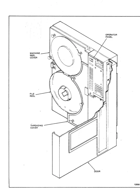
1-1 Model 292X MTS Front View (Vertical Mount)
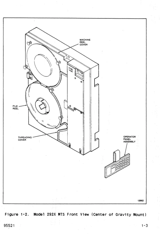
1-2 Model 292X MTS Front View (Center of Gravity
Mount) . . . .
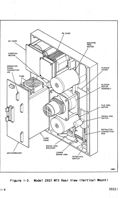
1-3 Model 292X MTS Rear View (Vertical Mount) . .
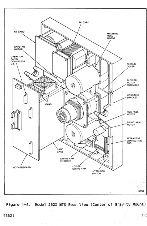
1-4 Model 292X MTS Rear View (Center of Gravity
Mount) . . . .
1-5 Model 292X MTS STORAGETEK Standard Card Cage
1-6 Model 292X MTS Industry Standard Card Cage
2-1 Operator Panel, Vertical Mount . . . .
2-2 Operator Panel, Center of Gravity Mount
2-3 Tape Thread Path . . . .
2-4 Tape Path Components--Tape Not Loaded
2-5 Start/Stop Mode Velocity Profile
2-6 Capstan Velocity Profile
3-1 Cables and Connectors . . . .
3-2 Interface Card Address, . . . .
3-3 IF Card Terminator and Address Switch Locations
3-4 Vertical Mounting Installation
3-5 Ver t i ca 1 Mount; ng Di mens ions . . . . .
3-6 Suggested Lifting Methods . . . .
3-7 Center of Gravity Mounting Dimensions
3-8 Storagetek Standard Interface Cabling
3-9 Storagetek Standard Interface Cable
Configuration . . . .
3-10 Industry Standard Interface Cabling.
4-1 MTS-User Interface Ci rcui ts . . . .
4-2 Command Initiation, Operation, and Completion
4-3 RDF or RDB Command TREQ, TRAK, and DATA Timing
4-4 Write Commands Initiating TREQ/TRAK/DATA Timing
(Applies to First Byte of Datal . . . .
4-5 WRT Command TREQ, TRAK and DATA Timing (Applies
to All Subsequent Bytes of Data)
5-1 Standard Industry Interface Circuits .
5-2 Interface Timing For 50 IPS Start Stop, Worst
Case . . . .
5-3 Interface Timing For 100 IPS Streaming, Worst
Case . . . .
6-1 MTS Block Diagram . . . .
LIST OF ILLUSTRATIONS CONT
Figure Title
6-2 Interface/Microprocessor Block Diagram (IF
Card) , . . . , . . . .
6-3 Write Path Block Diagram (DP Card)
6-4 Write Driver Block Diagram (WR Card)
6-5 Read Block Diagram (RD Card) . . . .
6-6 Read Path Block Diagram (DP Card) .
6-7 Capstan Servo System Block Diagram
6-8 Reel Servo System Block Diagram . .
6-9 Power System Block Diagram . . . .
7-1 Static and Dynamic Skew and Turnaround Jump
7-2 Capstan and Read/Write Head Alignment.
7-3 +Dif Analog Test Points
7-4 Bit Position Check . . . .
8-1 2920 MTS Deck (Front)
8-2 Read/Write Head . . . .
8-3 Swing Arm Assemblies
8-4 Retractor Assembly
B-1 PE Tape Format
B-2 GCR Tape Format . . . .
B-3 GCR Data Block Format (Sheet 1 of 3).
Page
6-3 6-5 6-7
6-8
6-10 6-13 6-14 6-16
7-3 7-4
7-7
7-11
8-2 8-6 8-8
8-17
Table
1 - 1 1-2 1-3 2-1 2-2 2-3 2-4 2-5 3-1 4-1 4-2 4-3 4-4 4-5 4-6 4-7 4-8 4-9 4-10 4-11 4-12 4-13 4-14 4-15 4-16 5-1 5-2 5-3 5-4 5-5 5-6 5-7 5-8 5-9 5-10 5-11 5-12 7-1
LIST OF TABLES
Title
Performance Specifications . . . . Nominal Access Time From Stop (milliseconds)
Power Requirements . . .
Generated Interblock Gap Lengths Selectable Interblock Gaps
Repos; t i on Times . . . . Nominal Reinstruct Times (Maximum Nominal Reinstruct Times (Minimum
PK Board Wiring for Input Power.
.
.
Gap) Gap)
STK Standard Interface Output Lines STK Standard Interface Input Lines MTS Address Line Decode . . .
Command Select Decode . . . . Density Select Line Decode . Select Multiplex Decode . . .
Error Conditions Setting DATA CHK . . . . Error Multiplex Bus Decode for Functional Mode Status Lines Asserted with WTM CHK
REJECT Codes (Sheet 1 of 2) . . . . Status Line Assertion For DMS/NOP Command Sheet
1 of 2 . . . .
Status Line Assertion For Diagnostic Wrap Mode Speed And Gap Selection Decodes . . . Diagnostics Extended Sense Bytes Summary . A-O Through C-F Sense Bytes Cross Reference Operational Sense Bytes Summary . . .
Industry Standard Interface Input Lines. Industry Standard Interface Output Lines Interface Connector J6 Pin Functions Interface Connector J7 Pin Functions MTS Address Line Decodes . . . . Functional Command Lines Decodes Diagnostic Command Lines Decodes Reject Codes (Sheet 1 of 2) . . .
Status Line Assertion for ISS Command . . . . Status Line Assertion For Diagnostic Wrap Mode Diagnostic Sense Bytes Summary . . . A-O Through C-F Sense Bytes Cross Reference
Capstan Alignment Instructions
Page
1-6 1-6 1 - 11
Table
9-1 9-2
LIST OF TABLES CONT
Title
Maintenance Routines .
Internal Diagnostics (Sheet 1 of 2) .
Page
CHAPTER 1
GENERAL INFORMATION
1. 1 INTRODUCTION
This chapter is an introduction to the Storage Technology
Corporation Model 292X Magnetic Tape Subsystem (MTS). This
chapter includes a general description of the physical and
functional layout of the MTS and includes the MTS specifications.
Two model types are available, the 2921 and the 2922. The 2921 has a tape speed of 50 inches per second (ips) (127 cmps) ,
start/stop. The 2922 has a tape speed of 50 ips (127 cmps)
start/stop and 100 ips (254 cmps) streaming.
1.2 GENERAL DESCRIPTION
The MTS (Figures 1-1 through 1-4) is an integrated tape
formatter/controller and half-inch (12.7 cm) tape drive packaged as a single self-contained unit (1x1). The MTS is a dual-density device capable of recording and reading ANSI compatible tapes in phase-encoded (PE) format at 1600 bits per inch (bpi) (63 bpmm) and group-coded recording (GCR) format at 6250 bpi (246 bpmm) at a tape speed of 50 (127 cmps) or 50/100 ips (127 cmps/254 cmps) , depending on the model.
The MTS is a low-cost, medium performance device intended for use
in normal tape processing and/or disk off-loading. The device
features automatic or semiautomatic tape threading/loading of
open reel sizes 7, B.5, and 10.5 inches; tension arm tape
buffering; microprocessor capstan servo and microprocessor reel servo; and on-board diagnostics for functional verification and fault detection.
Data can be read when tape is moving either forward or backward but recording can be performed during forward tape motion only. Performance specifications are shown in Table 1-1.
Nominal access time from stop ;s shown in Table 1-2. Access time is defined as the time from assertion of Busy on receipt of a read or write command at the interface to the time the beginning of the record is read from or written to tape. This is assuming tape starts from a stopped position, no turn-around condition is required, and tape is not positioned at BOT. See Chapter 2 for a
detailed description of the access time and interblock gap
MACHINE REEL COVER
FILE REEL
THREADING COVER
~
'r
4Jl '
~\®
\
~
~
THREADING COVER
OPERATOR PANEL ASSEMBLY
INTERLOCK SWITCH
CAPSTAN MOTOR
LOWER SWING ARM
INTERLOCK SWITCH
SWING ARM MOTOR
RETRACTOR CONNECTING ROD
Table 1-1. Performance Specifications
Tape Speed 50 ips/127 cmps 100 ips/254 cmps
Data Density
6250 bpi (246 bpmm) 6250 bpi(246 bpmm) GCR
PE
1600 bpi(63 bpmm) 1600 bpi(63 bpmm)Data Transfer Rate
GCR 313 kB/s 625 KB/s
PE
80 kB/s 160 KB/sAccess Time (nomi na 1 ) 5.0 ms See Table 1-2
Write Interbloek
(nomi na 1 ) Gap
GCR 0.45 in.(1.14 cm) See Chapter 2
PE 0.60 in. (1.52 em)
Rewind Time (nominal) 2.5 minutes 2.5 minutes
(2400-foot reel) (731,52 meter reel)
Table 1-2. Nomi na 1 Access Time F rom Stop (mill; seconds)
MODE lBG READ WRITE
Start/Stop 0.28 in./0.71 em 5.6 ms
-
-6250 bpi 0,30 in./0.76 em 6.0 ms
-
-246 bpmm 0.45 in./1.14 em 9.0 ms 6.0 ms
Start/Stop 0.50 in./1.27 em 5.6 ms
-1600 bpi 0.60 ; n. / 1 .52 em 7,6 ms 6,0 ms
63 bpmm
Streaming 0,28
-
1.2 in./ 12.0 ms-
-0.71
-
3.05 cm6250 bpi 0.30 in./0.76 em
-
- 12.5 ms246 bpmm
Streaming 0.5 - 1.2 in./ 12.0 ms
-1. 27 - 3.05 em
1600 bpi 0.60 in./1.52 em
-
-
12.5 ms1.2.1 Power Featu res
Models 2921 and 2922 operate from either a 120 Vac, 60 Hz power source or a 220 Vac, 50 Hz power source. Chapter 6 provides a description of the power supply.
1.2.2 Interface Features
Both models can be provided with either the StorageTek Standard Interface or the Industry Standard Interface (Pertec). The STK Standard Interface is described in Chapter 4 and the Industry Standard Interface is described in Chapter 5.
1.2.3 Mounting Options
Both models are available with either gravity (horizontal) mounting options.
installation.
1.2.4 Diagnostic Features
vertical or center of Chapter 3 describes each
The internal diagnostics programs are capable of detecting fault conditions in the tape subsystem and isolating failures within a
specific number of field replaceable units (FRUs). A unique
package is required for machines using the Industry Standard
Interface. Optional programs are available on floppy diskettes
to provide 292X interface verification and limited online
exercising. See Chapter 9 for details.
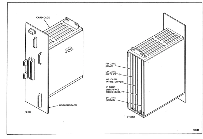
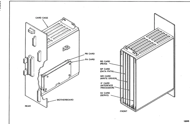
1.2.5 Electronics
The electronics of the MTS are located on five plug-in printed circuit cards located in a card cage below the operator panel.
The Industry Standard Interface requires two additional cards: PA and PB adaptor cards. These cards are identified in Figures 1-5
and 1-6. In addition, there;s an operator panel circuit card
(KK) and three power supply circuit cards: the AK and NK
I
. 00
REAR
CARD CAGE
MOTHERBOARD
RD CARD (READ) DP CARD (DATA PATH) WR CARD (WRITE DRIVER) IF CARD (INTERFACE PROCESSOR) SV CARD (SERVO)
<D
U1
.(J1
I\J -.0.
PB CARD
PA CARD
RD CARD
(READ) -~I
DP CARD
(DATA PATH)--uI, WR CARD
'IA'RITE DRIVER)~I II II
IWW II Ii"'1\oo.I
IF CARD
INTERFACE ~"I
~ROCESSOR)
II II Iml1.3 SPECIFICATIONS
Physical, environmental -and power requirements for the MTS are as follows:
1.3.1 Physical Dimensions
The nominal outside dimensions of the MTS are:
Height 24.5 inches (S2.2 cm)
Width 19.0 inches (48.3 cm)
Depth 1S.0 inches (40.S cm)
Projection 4.8 inches ( 12.2 cm) from RETMA
Weight 125 pounds (57 kg) mounting surface
1.3.2 Environmental Requirements
Temperature (Ambient Room Air):
Optimum Operating Non-Operating
Relative Humidity:
Optimum Operating Storage Shipping
+1S0C to +22°C (+SooF to +72°F)
+1SoC to +31°C (+SooF to +90oFl
-40oC to +70 oC (-400F to +158°F)
37% to 42%, noncondensing 20% to 80%, noncondensing 10% to 90%, noncondensing Any, noncondensing
The storage environment must not exist outside the limits of the operating environment for a period longer than six months.
The MTS must not be subjected to a temperature change greater than 8°C (15°F) per hour.
Altitude:
Operating
Non-Operating
Up to 1830 meters (S,OOO feet) standard Up to 3050 meters (10,000 feet) with
manual-assisted thread
1.3.3 Power Requirements
The MTS is designed to operate on anyone of the following single-phase power sources (refer to Table 1-3)
Table 1-3. Power Requirements
Nominal Voltage Maximum
Vo 1 tage Range Frequency Current
100 Vac 85-110 60 (± 1) Hz 4 amps
120 Vac 102-132 60 ( ± 1 ) Hz 4 amps
100 Vac 85-110 50 (± 1) Hz 4 amps
200 Vac 170-220 50 (± 1) Hz 2 amps
220 Vac 187-242 50 ( ± 1 ) Hz 2 amps
240 Vac 204-264 50 (± 1) Hz 2 amps
The MTS is assembled and shipped to operate from either a 120
Vac, 60 Hz power source or a 220 Vac, 50 Hz power source.
CHAPTER 2
OPERATION
2.1 INTRODUCTION
This chapter describes the operator panel functions and status indicators, the common MTS operating procedures, and the required operator maintenance.
2.2 POWER ON/OFF SWITCH
The Power On/Off switch is used to power up or power down the MTS. When powered up, the MTS initializes and invokes a series of power-up diagnostics.
2.3 DISPLAY
The operator panel contains a four-character display. When the
MTS is in Online Status, the display is blank. During machine check conditions, the display contains a three-digit fault code. When theMTS is offline and at idle, the display contains four
dashes indicating that the MTS is ready to accept diagnostic
commands . . When a key is depressed, all segments of the display are lit to indicate that the key has been recognized and
accepted. When pressure is removed from the key, the display
returns to its previous state.
Throughout this manual, display conditions are shown enclosed
within parentheses. To summarize the display conditions and their meanings:
( )
(----) (@n ) (@nn ) ( nn) (nnnn)
( ??)
(????)
( nnn)
Onl ine
Offline, panel idle, test successfully completed Executing test
Executing test
Displaying data (flashing if from probe) Displaying address
Request for data or test 10 input Request for address input
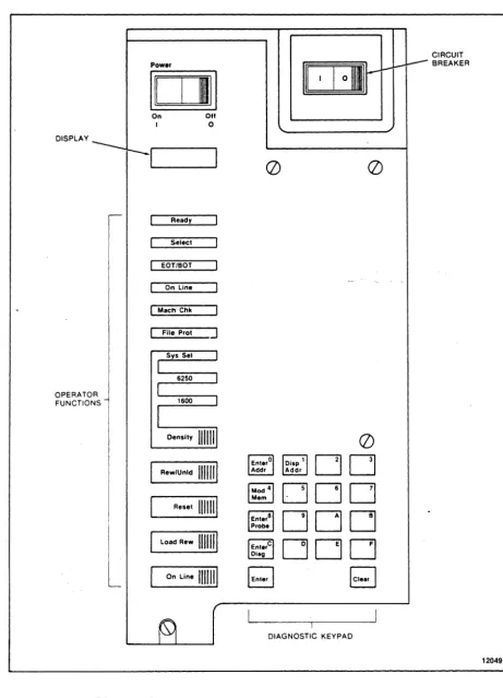
2.4 OPERATOR FUNCTIONS AREA
The operator functions area of the operator panel and 2-2) provides status indicators and a keypad control of the normal functions of the MTS.
2.4.,1 Ready Indicator (Green)
(,Figures 2-1 for operator
The Ready indicator is illuminated when the MTS is fully loaded and not performing a rewind operation. The indicator is active whether or not the MTS is in Online Status.
2.4.2 Select Indicator (Yellow)
The Select indicator is illuminated when the MTS is in Online Status and has been selected for use by the USER (that is, the MTS Address lines match the address of the MTS).
2.4.3 EOT/BOT Indicator (Green)
The EDT/BOT indicator is illuminated when EDT or BOT Status is set in the MTS; that is, when the BOT marker is detected by the BOT sensor or when the EDT marker has been detected by or is past the EDT sensor. When the indicator is lit at. EDT, it remains illuminated until a rewind or backward read operation moves the EDT marker back past the EDT sensor.
2.4.4 On Line Indicator (Green)
The On Line indicator is illuminated when Online Status is set in the MTS; that is, when the MTS is available to the USER.
2.4.5 Machine Check Indicator (Red)
The Machine Check (MACH CHK) indicator flashes to signal either a load check, which may be operator correctable, or to signal a malfunction of the MTS that requires service. A fault code of
three characters will be posted in the display.
2.4.6 File Protect Indicator (Red)
The File Protect (FILE PROT) indicator is illuminated when tape is loaded and a write enable ring is not in place on the file reel. ,Write operations can not be performed when this indicator
DISPLAY
OPERATOR FUNCTIONS
Power
1011
On OffI 0
Ready
Select
EOT/BOT
On Line
I Mach Chk
File P r o t ]
Reset
IIIml
Load Rew 111111
I
On Line 1111111II I
I
01111111(])
(])
DO
~DDD
DOD
DOD
I
DIAGNOSTIC KEYPAD
CIRCUIT BREAKER
C8JREADY
a
C8J SELECT C8J EOT/BOT
C8J ON LINE C8J SYS SEL
(
REW UNLD)
ENTERo~DDAODR AODR
(
RESET)@[]DDD
(
LOAD REW)
~~6~aDDD
C8J MACH CHK C8J 6250(
ON LINE)
~I~RcDDD
C8J FILE PROT C8J 1600(
DENSITY) (ENTER)DD(CLeAR)
12039
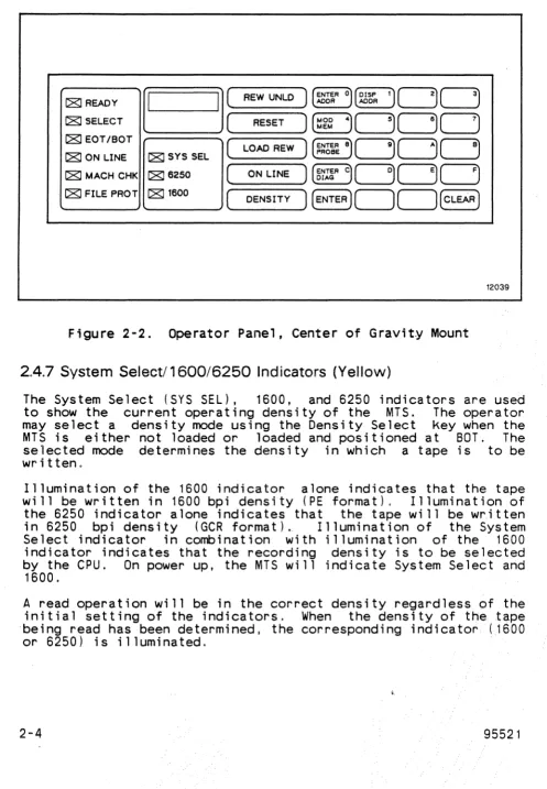
Figure 2-2. Operator Panel, Center of Gravity Mount
2.4.7 System Selectl 1600/6250 Indicators (Yellow)
The System Select (SYS SEL), 1600, and 6250 indicators are used to show the current operating density of the MTS. The operator may select a density mode using the Density Select key when the MTS is either not loaded or loaded and positioned at BOT. The selected mode determines the density in which a tape is to be written,
Illumination of the 1600 indicator alone indicates that the tape will be written in 1600 bpi density (PE format), Illumination of the 6250 indicator alone indicates that the tape will be w~itten
in 6250 bpi density (GCR format).. Illumination of the System Select indicator in combination with illumination of the 1600
indicator indicates that the recording density is to be selected by the CPU. On power up, the MTS will indicate System Select and
1600.
A read operation will be in the correct density regardless of the initial setting of the indicators, When the density of the tape ·being read has been determined, the corresponding indicator (1600
2.4.8 Density Select Key
The Density Select (DENSITY) key is used to select a recording density when the drive is unloaded or tape is loaded and at BOT. Successive actuations of the key causes the MTS to cycle through the possible density modes. Upon power up, the MTS will be set to SYS SEL/1600 mode. Pressing DENSITY causes the MTS to go to 1600 bpi density. A second press causes the MTS to go to 6250 bpi density. Entering DENSITY a third time returns the MTS to SYS
SEL/1600 mode.
Execution of a diagnostic routine may cause the density status of the MTS to change. A tape load operation will reinitialize the MTS to SYS SEL/1600 mode.
2.4.9 Rewind/Unload Key
The Rewind/Unload (REW/UNLD) key is used to unload tape. If tape is not at BOT when the key is pressed, a high speed rewind to BOT is initiated, the swing arms are retracted, and tape is unloaded from the tape path. Select and Ready Status are reset by this key. This key is not accepted if the MTS is in Online Status.
2.4.10 Reset Key
The Reset key is used to generate a subsystem reset. Pressing
this key resets Select, puts the MTS in Offline Status,
terminates any operation and tape motion that is in progress, clears any machine check condition, and returns the display to
idle (----).
2.4.11 Load/Rewind Key
The Load/Rewind (LOAD/REW) key serves a dual purpose. If tape is not loaded, this key is used to load tape and position tape at BOT. If tape is loaded, this key causes tape to be rewound and positioned at BOT. This key ;s disabled if the MTS is in Online Status.
2.4.12 On Line Key
2.5 DIAGNOSTIC KEYPAD
Commands entered on the diagnostic keypad (Figures 2-1 and 2-2)
allow access to various functions. These include maintenance
programs execution, internal diagnostics execution, memory
examination and modification, and a continuous readout of a
memory space location (probe). The operations available are
dependent upon the status of the MTS and the current display
contents. The keypad will not respond when the MTS is in Online
Status or if a machine check is present (nnn). While idle
(----) or error ( nnn) is present, all panel functions are
available. During the execution of a maintenance program or
diagnostic routine (@n ) or (@nn ), only memory read functions are available (Enter Address, Enter Probe, and Display Address). The Reset key serves to return the panel to an idle condition
(----),
The main function of each key on the keypad is marked on the key.
Some keys have alternate control functions. The protocol for
using the diagnostic keypad consists of entering a control
function and then entering data characters as required. The
display contains input and output symbols appropriate to the function in process.
The diagnostic keypad is also used to enter data characters. The data character associated with a given key appears in its upper
right corner.
2.5.1 Enter Address Key
The Enter Address key is used to select an address from which data display is desired. Pressing the Enter Address <ENTER ADDR>
key allows the entry of a hexadecimal number representing a
location within the memory of the MTS controller. The display prompts for the entry with four question marks
(????)
until the first entry is made. The first entry then appears right-justified in the display with subsequent entries producing a shift left on the display. Any number of entries may be made. If the target address desired is the same as that most recently referenced, a press of the Enter key directly following the prompt display is sufficient.2.5.2 Display Address Key
When using the Enter key to display. a long series of memory
locations, it may be necessary to determine the location
currently being displayed. The Display Address key is used to
display the MTS current address. Pressing the Display Address
(DISP ADDR> key causes the current address to be displayed as
four hexadecimal digits. Press the Enter key to display the
contents of this address as in a normal enter address sequence.
The address last displayed is stored so that normal machine
operation will not destroy it. The Display Address key may then
be used at any time (for instance, following a diagnostic
routine) and the Enter key may be pressed to recall a frequent memory location.
If the Display Address key is pressed following subsystem power up and before the Enter Address function is used, memory location 0000 is displayed.
2.5.3 Modify Memory Key
The Modify Memory (MOD MEM> Key is used to modify a writeable memory location within the MTS controller. This Key is recognized only while data from the target location (from an (ENTER ADDR> or
(DISP ADDR> Key sequence) is being displayed. No memory
modification is allowed while a diagnostic routine is executing. If this Key is pressed at any other time, there will be no response.
CAUTION
If the memory is modified, MTS operation is not guaranteed.
Following the actuation of the Modify Memory key, the display
prompts for a byte value input (two hexadecimal entries) by
displaying two question marks ( ??). The operator may now use as many Keystrokes as necessary to produce the required data in the display. Each entry results in a shift left of the two digits on
the right (the two digits on the left remain blank).
2.5.4 Enter Probe Key
The Enter Probe <ENTER PROBE) key is used· to cause a constant ly updated display of a particular controller memory space location. The updating is indicated by a rapidly flashing byte on the display.
Following the actuation of the Enter Probe key, the display
prompts for address input by displaying four question marks
(????).
Input of the address is as described in Section 2.5.1.Following the delimiting Enter key actuation, the contents of
that address is displayed in the two digits on the right. The
display flashes the byte continuously at about ten times per
second. The system may be brought back to idle by using either the Clear or Reset key.
2.5.5 Enter Diagnostic Key
The Enter Diagnostic <ENTER DIAG> key is used to initiate the entry of subsystem self-contained diagnostic routine numbers. After pressing the Enter Diagnostic key, the display prompts for the entry of a two-digit hexadecimal routine identification by displaying two question marks (
??).
The operator may now use as many keystrokes as necessary to produce the required 10 in the· display. Each entry results in a shift left of the two digits onthe right (the two digits on the left remain blank).
When the desired routine number appears in the display, pressing the Enter key results in the attempted execution of that routine. The 10 is displayed while the routine is being executed. If the
routine is not successful, fault codes are displayed as three
hexadecimal digits. If the routine is successful, completion is indicated by the idle display (----).
A routine in progress may be terminated by pressing the Reset key.
2.5.6 Enter Key
2.5.7 Clear Key
The Clear <CLEAR) key is used to clear the last data and/or address entry in the display and return to the prompt mode (question marks .in the display) of the last function attempted. If the MTS is currently in a prompt mode (no entry has been made), the MTS returns to an idle state and awaits a function request. If a diagnostic routine is being executed, its ID is again displayed.
2.6 TAPE THREADING OPERATIONS
MTS operations are provided by the operator functions keypad on the operator panel. Machines with vertical mount can have tape
loaded automatically, semiautomatically, or manually. Machines
with center of gravity mount can have tape loaded
semiautomatically or manually. Procedures are described below.
2.6.1 Automatic Thread/Load--Vertical Mount
The automatic thread/load is the normal procedure for vertically mounted machines.
1. Power up the MTS, if necessary; the swing arms automatically extend and then retract. Ensure the machine reel cover and
the thread cover are closed.
2. Unlatch the file hub locking lever. Place the reel of tape
3.
on the file reel hub, then relatch the lever. Make certain that the reel is secure.
Press LOAD/REWIND. sensqrs are enabled, on.
The vacuum blower motor turns on, the and power for the reel motors is turned
The MTS initially assumes that the tape leader is positioned at the entrance of the tape threading path and rotates clockwise to slip the tape leader into the path. If tape is not sensed at the EDT/BOT sensor within a given amount of time, the file reel reverses and attempts to position the tape leader using the leader sensor. If the leader cannot be sensed, it is assumed that the leader is stuck to the tape reel with static and 'the file reel is rotated rapidly to try
to break the static. When the leader is sensed, it is
positioned at the entrance of the tape threading path.
Tape Present. When the tape has wrapped the machine reel hub, it ;s sensed as Tape Attached and the blower motor turns off. If any of these steps fails to occur in the prescribed time,
a mark is counted against the load. If three marks are
counted, the load has been unsuccessful and a ,fault code is
posted in the display. ..
When Tape Attached is sensed, the tape is rnc:)ved forward until the begi nni ng-of- tape (BOT) marker is found. Tape cont i nues .. to move forward a few feet and stops. The swing arms are lowered into their normal operating area.
Tape is rewound to BOT. When BOT is sensed and tape is
stopped, the file reel is moved such that the MTS logic can determine file reel size. Tape then moves forward past BOT and a series of start/stop operations is run forward and then
repeated backward. These start/stops allow the adaptive
features of the capstan control algorithms to initialize for the current tape.
Tape is then brought back to BOT and stopped. The Ready
indicator is illuminated and the MTS is ready for operation.
4. Pressing ON LINE after the Ready indicator is lit enables the MTS to accept commands from the user.
2.6.2 Semiautomatic Thread/Load-Vertical Mount
If the tape does not load successfully during automatic
thread/load, the semiautomatic thread/load procedure can be used.
1. Power up the MTS and load the file reel onto the hub.
2. Press the Load/Rewind button twice,
interval between presses. with a four second
3. Manually and slowly rotate the file reel clockwise to allow the tape leader to drop into the tape path until the file motor moves on its own.
2.6.3 Semiautomatic Thread/Load--Center of Gravity Mount
The semiautomatic thread/load is the normal procedure for center of gravity mounted machines.
1. Power up the MTS and load the file reel onto the hub.
3. Manually and slowly rotate the file reel clockwise and pull the tape leader into the tape path cavity.
4. Continue to rotate the file reel until enough tape leader is released into the tape path for the file motor to move on its own.
2.6.4 Manual Thread/Load--Vertical or Center of Gravity Mount
If the blower motor is not operating, tape must be loaded
manually. Refer to 2-3
1. Power up the MTS and load the file reel onto the hub.
2. Open the thread cover and remove the machine reel cover.
3. Pull the tape leader under the lower swing arm roller,
through the tape path, over the capstan wheel, under the
upper swing arm roller and over the machine reel.
4. Manually wind the upper reel clockwise, using a finger to
hold the tape leader against the machine reel hub, until the tape is secured to the reel.
5. Press the Load/Rewind button.
2.6.5 Midtape Load, EOT Area
If a load is required when the tape is in the EDT area (after POWER DOWN or LOOP OUT), a load problem may occur. A forward search for BOT will be initiated and may cause tape to be pulled off the file reel. To avoid this, use the following procedure:
1. Power up the machine if necessary (allow diagnostics to
comp lete) ,
2. Press' UNLOADI •
3, Allow the tape to rewind onto the file reel for about 10 seconds.
4. Press I RESETI to halt the unload,
5. Press I LOAD' for a midtape load.
2.6.6 Rewi nd
TAPE PATH
CAPSTAN WHEEL
READ/WRITE HEAD
CLEANER BLOCK
2. Press LOAD/REWIND. Tape rewinds at high speed, passes BOT, stops, moves forward to the BOT marker, and stops in Ready Status.
2.6.7 Unload
1. If the MTS is in Online Status, press RESET.
2. Press REWIND/UNLOAD. If tape is positioned off BOT, it will rewind at high speed, pass BOT, stop, and move forward to t~e
BOT marker. With tape at BOT, the swing arms retract, tape 1S
unloaded onto the file reel, and power for the reel motors is turned off.
2.7 OPERATOR MAINTENANCE
Because cleanliness is crucial to successful magnetic tape
operations, there are several operator cleaning procedures which should be performed daily or after each eight-hour shift under normal operating conditions.
These procedures are for cleaning components of the tape path
(Figure 2-4). Cleaning should be done using only Storage
Technology Hub and Transport Cleaner Fluid to moisten a lint-free
cloth or foam-tipped swab. Refer to Appendix B for the part
number of the cleaning supplies. After applying cleaner, allow a few minutes for excess fluid to evaporate before mounting a tape.
2.7.1 Read/Write Head and Tape Cleaner Block
WARNING
The tape cleaner blade is sharp. Use extreme care when handling the tape cleaner block.
Clean the read/write head and the tape cleaner block using a lint-free cloth moistened with Hub and Transport Cleaner Fluid. Make certain the head and cleaner block are free of oxide deposits. Use foam-tipped swabs to clean the cleaner block.
2.7.2 EaT/BOT and Leader Sensors
CAPSTAN WHEEL
UPPER TAPE GUIDE
READ/WRITE HEAD
TAPE CLEANER BLOCK
LOWER TAPE GUIDE
EOT/BOT SENSOR
THREADING DIVERTER
2.7.3 Tape Guides, Rollers,. and Swing Arms
Clean the two tape guides, the three fixed rollers, and the four swing arm rollers using a lint-free cloth moistened with Hub and Transport Cleaner Fluid. To reach otherwise inaccessible areas, foam-tipped swabs may be used. If necessary, the edge of a data processing card may be used to clean the flange corners of the guides.
2.7.4 Capstan
Clean the capstan using a lint-free cloth wrapped around the
index finger and moistened with Hub and Transport Cleaner Fluid.
CAUTION
Do not touch the outer, tape-contacting surface of the capstan with the bare hand as the surface is
sensitive to contamination. Always use a cloth
when handling the capstan and grip only the hub of the capstan.
With the free hand, slowly rotate the capstan hub while wiping
the capstan surface with the moistened cloth. Two or three
revolutions is sufficient. Wipe the capstan with a dry, lint-free cloth to remove excess cleaner fluid.
2.7.5 File Reel Hub
Clean the expansion surface of the file reel hub using a
lint-free cloth moistened with Hub and Transport Cleaner Fluid.
2.8 TAPE MOTION CHARACTERISTICS
The MTS will operate at a nominal tape velocity of 50 ips in start/stop mode or 100 ips in streaming mode.
NOTE
The MTS will default to 50 ips mode at power on.
2.8.1 Start/Stop Mode
during which the MTS can be given a new command and remain traveling at full speed. The nominal holdover distances at 1600 bpi are 0.25 inches (0.64 cm) for a read and 0.19 inches (0.48 cm) for a write, which translates into reinstruct windows of 4.0 milliseconds and 2.8 milliseconds, respectively.
If the MTS is reinstructed during the deceleration ramp in either density, tape will not come to a full stop. Refer to Figure 2-5.
0.43 IN. GAP
0.37 IN. GAP
•••
j
o IPS _ _ _ _ _
::L _____ _
f - - - + - - 5 . 0 MILLISECONDS NOMINAL
Figure 2-5. Start/Stop Mode Velocity Profile
12040
In GeR, if a write reinstruct is issued within the first half of
the deceleration period (within 2.5 milliseconds) a 0.37 in.
(0,94 cm) gap will result. The gap after a full stop will be 0.43 in. (1.09 cm). See Figure 2 - 5.
2.8.2 Streaming Mode
In the 100 ips s treami ng mode, tape shou ld not s top at all if reinstructed promptly enough. However, if the end of the lnterblock Gap is reached and a new command has not been received, then a repositioning cycle is performed. Repositioning is accomp.lished relatively quickly by using the capstan to stop tape and back it up to the point where it is ready for the next
instruction. Meanwhile, the machine and file reels are
decelerated more slowly, with the difference i'n tape being taken up by the tension arm buffer. The reels need not come to a full stop before the next conmand is executed. If the time between commands is long enough, the reels will stop, but will not back up. See Figure 2-6.
+ 100 IPS _ _ _ _ --,.
o IPS _ _ _ _ _
-100 IPS _ _ _ _ _ _ _ ~.~C _ _ _ ~D
t---Tl---~
T1 = REPOSITION TIME T2 = START TIME T3 = ACCESS TIME
Figure 2-6. Capstan Velocity Profile
12041
command is received. The nominal streaming mode start time
between E and F is 10.0 milliseconds. Point G denotes the
beginning of the next record on tape.
2.9 INTERBLOCK GAP (IBG) GENERATION
Interblock gaps will be generated by the MTS as shown in Table 2-1. In the 50 ips start/stop mode, the nominal GCR IBGs wi 11 vary as a function of reinstruct time. In this mode, tape will
decelerate but need not stop if reinstructed early enough,
causing the shorter 0.37 in. (0.94 cm) nominal gap to be written.
When in the 100 ips streaming mode, variable gaps may be
selected. The gap size is then a function of how quickly the MTS is reinstructed, up to the maximum length selected. For example, if 0.9 (2.29 cm) inch maximum gap length is selected and the MTS is reinstructed before tape moves that far, then a shorter gap (between 0.3 and 0.9 inch (0.76 and 2.29 cm) for 6250 bpi) will be generated. If not reinstructed in time, then a repositioning cycle is necessary and the next gap generated is the short gap length listed under fixed. For example, after repositioning in
6250 bpi, a 0.30 in. (0,76 cm) gap will be generated. The maximum
gap lengths which may be selected are shown in Table 2-2.
Table 2-1. Generated Interblock Gap Lengths
50 IPS START/STOP 100 IPS STREAMING
DENSITY MIN NOMINAL MAX FIXED VARIABLE
(ANSI)
6250 BPI 0.28 0.37 - 0.43 0,50 0.30 0.30 - SELECT
0.71cm 0.94 - 1.09cm 1 .27cm 0.76cm 0.76cm - SELECT
1600 BPI 0.50 0.60 0.65 0.60 0.60 - SELECT
1 .27cm 1.52cm 1.65cm 1 . 52cm 1.52cm - SELECT
When reading either 6250 bpi or 1600 bpi in the 100 ips streaming mode, a reposition cycle will occur if a gap of 1.2 in. (3.05 cm)
is traversed or no reinstruct is received before the next block is encountered. This is independent of the gap size selected. The minimum read gap which is supported is 0.28 in. (0.71 cm) in 6250 bpi and 0.50 in. (1.27 cm) in 1600 bpi. If the next block is encountered before being reinstructed, tape will be repositioned relative to the start of this next block, rather than to the
beginning of the lBG, so that minimum access time can be
Table 2-2. Selectable Interblock Gaps
DENSITY GAP SIZE
6250 BPI 0.3, 0.6, or 0.9 in.
0.76, 1.52, or 2.29 cm
1600 BPI 0.6, 0.9, or 1.2 inches
1 .52, 2.29, or 3.05 cm
2.10 REPOSITION TIMING
Reposition time ;s the time to get from Point A to Point E in Figure 2-6. It ;s a function of the maximum interblock gap length
selected. For the gap lengths shown in Table 2-2, the
corresponding reposition times are shown in Table 2-3.
Table 2-3. Reposition Times
INTERBLOCK GAP
DENSITY 0.3 in. 0.6 ; n. 0.9 in. 1.2 in.
0.76 cm 1.52 cm 2.29 cm 3.05 cm
6250 BPI 50 ms 53 ms 56 ms
-1600 BPI - 50 ms 53 ms- - 56 ms
----2.11 REINSTRUCT TIMES
Reinstruct time is defined for streaming mode as the amount of time from the completion of a command when the interface output signal busy ;s reset to the time when tape moves to the latest point in the interblock gap beyond which a reposition cycle is required. These times are a function of gap size, density, and read- or write-type operation. Table 2-4 shows the times for the
longest gaps and Table 2-5 for the shortest gaps.
2.12 50/100 IPS SPEED CHANGE
Changing speeds between 50 ips and 100 ips is accomplished by an interface command sequence. The MTS can change speed at various times, for example, at beginning of tape or after reading some
Table 2-4. Nominal Reinstruct Times (Maximum Gap)
DENSITY INTERBLOCK GAP READ WRITE
(BPI) (INCHES) (MILLISECONDS) (MILLISECONDS)
6250 BPI 0.9 in. 8.0 ms 6.5 ms
2.29 cm
1600 BPI 1.2 in. 11.0 ms 9.5 ms
3.05 cm
Table 2-5. Nominal Reinstruct Times (Minimum Gap)
DENSITY INTERBLOCK GAP READ WRITE
(BP 1) ( INCHES) (MILLISECONDS) (MILLISECONDS)
6250 BPI 0.3 in. 2.0 ms 0.5 ms
0.76 cm
1600 BPI 0.6 in. 5.0 ms 3.5 ms
1.52 cm
.
This will cause tape, if loaded, to be repositioned and the tension arms to move to a new position. The amount of time to accomplish this change is:
100 ips to 50 ips: approximately 400 milliseconds, 50 ips to 100 ips: approximately 700 milliseconds.
2.13 TURNAROUND DELAYS
Turnaround delays are encountered between certain command sequences. For example, when a Write command follows a Read Forward or Read Backward command, the erase head must be properly repositioned within the Interblock Gap. When a Read Backward (Reverse) follows a Write, a gap is erased in the forward direction before the backward (reverse) command is executed.
In the 100 ips mode a change in direction will necessitate a delay even if the swing arms are stable. Since the stop position forward is different from the stop position backward, a change in direction means the swing arms must first move toward their new stop position before any motion can take place. This change of stop positions takes about 160 milliseconds.
2.14 DUTY CYCLE
There is no duty cycle limit for 50 i~s start/stop or 100 ips
streaming mode. If the tape speed 1S operated in 100 ips
start/stop operation and the number of starts exceeds
CHAPTER 3
INSTALLATION
3.1 INTRODUCTION
This chapter provides instructions for inspection, power set up, preliminary checkout, and cabinet mounting of the MTS.
Each MTS is shipped on a foam cushion shipping pallet assembly
with a corrugated overcarton. The container provides stability
and protection for the MTS and should not be removed until the unit is ready to be mounted into an equipment rack. Provision has been made for an operational checkout of the MTS while on the shipping pallet.
3.2 INSPECTION
1. Position the packaged MTS upright at the operational checkout station.
WARNING
The MTS and its shipping carton weigh
approximately 150 pounds (68 kg). Use
appropriate mechanical aids and sufficient
personnel when moving the unit to prevent
personnel injury or equipment damage.
2. Remove the unpacking instructions and any other documents
from the exterior of the shipping carton.
3. Visually inspect the exterior of the shipping carton for
evidence of physical damage that may have occurred in
transit. Verify that a shock watch is located on the carton and inspect the bubble. A red bubble indicates that damage has occurred. If any damage is found or if no shock watch is located on the carton, promptly report the condition to a company representative.
4. Remove only the top of the shipping container (corrugated
carton, corrugated inner tray, and top foam cushion). The MTS . should be sitting upright, supported by the bottom of the
5. Remove the front cushion foam from the lower front area of the cushion pallet. This permits access to the front of the MTS.
6. Open the taped end of the antistatic polybag. Pull the bag completely down around the sides of the MTS. Cut the po1ybag as necessary to permit free opening of the front door of the MTS. Do not attempt to remove the polybag from under the MTS until ready to mount the unit in a rack.
7. Check all items against the shipping list to verify container contents. Verify that the serial number of the unit corresponds to that on the shipping invoice. Contact a company representative in case of a packing shortage or
incorrect serial number.
8. Visually inspect the MTS for evidence of physical damage that may have occurred during handling or in transit. If any damage is found, promptly report the condition to a company representative.
9. Open the front door of the MTS and remove any cellophane and tape.
10. Remove all packing materials from cables and connectors . Check for bent or . mi sa 1 igned pins and straighten as necessary.
11, Verify that all cable connections are tight. (Refer to Figure 3-1 . )
12. Check for· loose hardware throughout the MTS and tighten as necessary. Ensure that all DIP packages on the circuit cards
in the card cage are secure in their sockets.
3.3 POWER CONNECTION
The input frequency rating for the unit is determined by the frequency