Alarm Clock With Keypad Entry
ECE331 Final Project
Fall 2007
A. Introduction
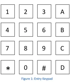
The goal of this project was to create an alarm clock using the MC9S12C32, Hitachi-style LCD panel,
16-key keypad, and speaker. The keypad is used for entering the time of the clock and the time of the
alarm. The clock is kept track of by using time-based interrupts which interrupt every 10 ms. Every time
the 10 ms interrupt occurs, the hour, minute, second, and centisecond (10 ms) variables are updated
accordingly. To input an alarm time, the user may push the “*” key. The LCD will then go into an alarm
entry mode. At this point, the user will be prompted to put in the hours, minutes, and seconds they
would like the alarm to go off on. While the user is in the alarm entry mode, the clock will still be able to
keep track of the time, as we do not want time to stop when an alarm is being entered. The time may
also be entered in a similar way by pressing “#.” To turn on the alarm, the user may press “A”.
B. External Specification: User Manual
§
The “Alarm Clock with Keypad Entry” may be used to keep track of time and set an alarm. A
keypad is used to avoid the need to awkwardly press multiple buttons countless times in order to set the
time, as is done in traditional alarm clocks. NOTE: All times are in “military time” (i.e. 22:48:00 would be
10:48:00 p.m.).
Time Entry
To enter the current time, press the “#” button. The display will stop incrementing the time,
and an “S” will be displayed to the right of the time. Press any of the numeric buttons (0-9) to enter the
ten’s hour digit(hh:mm:ss). The time will be updated and displayed to reflect the change of this bit.
Next, set the unit’s hour digit (hh:mm:ss). Continue setting the time in this order, from leftmost digit to
rightmost digit. If you would like to accept your changes before entering the remaining digits, hit the
1
2
3
A
4
5
6
B
7
8
9
C
*
0
#
D
“#” sign again. For example, press # to enter time entry mode, then press “1” then “2” to set the hour
to 12, and press “#” to leave the remaining digits as they are.
Alarm Set
To set the alarm, press the “*” key. The display will stop updating the current time, and a “M”
will be displayed to the right to show that you are in the alarm set mode. You will be able to enter the
time the alarm will go off just as the time is entered in the “Time Entry” section above (i.e. from leftmost
to rightmost digit). To turn the alarm on, press one of the keys “A”,”B”,”C”, or ”D”. When one of these
keys is pressed, the alarm will be turned on or off. When the alarm is on an “A” will be displayed to the
right of the current time.
Turn Off Alarm
When an alarm is sounding, you may turn it off by hitting one of the keys “A”, “B”, “C”, or “D”.
This will turn off the alarm sound, as well as the alarm, until the alarm is set again (i.e. an “A” is to the
right of the current time).
C. Internal Operation
The basic structure of the program is based on case statements. The system essentially implements
a state machine. The ports and variables are all initialized at program entry. The hardware diagram can
be seen in the Appendix. Port T is used for the keypad input, and port AD is used for the LCD output.
The program uses the same LCD display routines used in Lab 5. Port M2 is used to drive a transistor that
powers a speaker.
The main loop of the program checks to see if a key is pressed, and then determines what key is
pressed. The processKey subroutine sets a variable, “rc”, based on the key pressed. Since this
subroutine runs every time the main loop runs, it also determines whether the current time equals the
alarm time. If the current time equals the alarm time, the mode is set to sound the alarm. The program
uses a case statement on the variable “mode” which stores what state the program is in. There are 5
different states: TIME_DISPLAY, TIME_ENTRY, ALARM_ENTRY, ALARM_ENABLE, and ALARM_SOUND.
The purpose of these states can be seen from their names.
Just as in Lab5, there is an interrupt routine that interrupts every 10ms, and updates the time
variable. This interrupt service routine is called no matter what, since it is the only interrupt, all other
code runs in subroutines or the main function. This was necessary to make sure the time updated even
while the program was doing other things.
D. Testing Procedures and Results
The general testing procedure implemented in our design was iterative testing. We slowly coded
portions of the program and then tested them. We started off with the LCD display and clock code from
lab 5. We had to put the LCD display on port AD rather than port T, since we decided to connect the
keypad to port T. We edited the lab 5 code to set the LCD display to port AD and then connected the
keypad (port T) and LCD display (port AD). This was then tested to make sure the LCD and clock still
worked. After this, we created code to receive input from the keypad. This was very similar to lab 3,
however slightly modified to fit into our program. This was tested by writing the inputted key pressed
onto the LCD display. The previous two steps were relatively easy to implement.
E. Bill of Materials
2. 16-key, 8 pin keypad (Available from parts room) - $5.95
3. Hitachi-style LCD Display (Available from parts room) - $3.50
4. Speaker (Available from parts room) - $2.00
5. Breadboard (or circuit board) - $2.00
6. Various Wires - $2.00
7. LM7805 - $0.5
8. LED - $0.2
9. 0.1 µF capacitor - $0.05
10. 2 kΩ resistor - $0.05
11. 10 Ω resistor - $0.05
12. 100 Ω resistor - $0.05
Appendix
Circuit Schematic
L C D 1 1
V c c = 5 V
L C D 1 4 P 5
S p e a k e r
Q 1 3 9 0 4
L C D 1 3
D 1 P w r L E D
P 7
P 2
L C D 1
G r o u n d B u s
L C D 6
R 5 1 0 0 o h m
P 4
L C D 4
L M 7 8 0 5
3
2
1
I n p u t G N D
O u t p u t
C 1
0 .1 U F
L C D 1 2
R 5 1 0 o h m
P 6
P 0
R S T S W
L C D 3
R e d + 5 V D C P o w e r B u s ( T o p o f B r e a d b o a r d )
R 4 2 k
+
7 - 1 5 V D C D C A d a p t o r
R 5 1 k
L C D 2
P 1
L C D 5 P 3
C S M 1 2 C 3 2 J 1 C o n n e c t o r
1 2 3 4 5 6 7 8 9 1 0 11 12
13 15 17 19 21 23 25 27 29
3 0 31 32 2 8 26 2 4 22 2 0 18 1 6 14 3
3 35 37 39
3
4 36 38 40
Main.c:
#include <hidef.h> /* common defines and macros */ #include <mc9s12c32.h> /* derivative information */ #pragma LINK_INFO DERIVATIVE "mc9s12c32"
#include "main_asm.h" /* interface to the assembly module */ #define NUM_KEYS 16
enum operationMode { NO_KEY,
TIME_DISPLAY, TIME_ENTRY, ALARM_ENTRY, ALARM_ENABLE, ALARM_SOUND, DUPLICATE_KEY, INVALID_KEY, DIGIT_KEY };
/* coded/decoded key value tables */
static unsigned char keys[] = {0xB7, 0x7E, 0xBE, 0xDE, 0x7D, 0xBD, 0xDD, 0x7B, 0xBB, 0xDB, 0xEE, 0xED, 0xEB, 0xE7, 0x77, 0xD7}; static unsigned char decodedKeys[] = {0x30, 0x31, 0x32, 0x33, 0x34, 0x35, 0x36, 0x37, 0x38, 0x39, 0x41, 0x42, 0x43, 0x44, 0x2A, 0x23}; /* Global TIME Variable */
static unsigned char time[] = {
0x30, //Hours (digit 1) 0x30, //Hours (digit 2) 0x30, //Minutes (digit 1) 0x30, //Minutes (digit 2) 0x30, //Seconds (digit 1) 0x30, //Seconds (digit 2) 0x30, //Centiseconds (digit 1) 0x30 //Centiseconds (digit 2) };
static unsigned char alarmTime[] = { 0x30, //Hours (digit 1) 0x30, //Hours (digit 2) 0x30, //Minutes (digit 1) 0x30, //Minutes (digit 2) 0x30, //Seconds (digit 1) 0x30, //Seconds (digit 2) 0x30, //Centiseconds (digit 1) 0x30 //Centiseconds (digit 2) };
/* Status Digits "ASM" * A: Alarm is enabled * S: Set time mode * M: Set alarm mode */ static char dispDigits[] = { 0x20, //A digit 0x20, //S digit 0x20, //M digit
0x00 //NULL terminate so we can use as string };
static unsigned char keyVal; //most recent key press static unsigned char prevKey = 0x00; //most recent processed key static unsigned char keyPress = 0x00; //current key value
/* Function Prototypes */
extern void updateTimeISR(void); static void displayTime(void);
static int getKey(void); static int processKey(int press); static void delay(int count);
static int setTime(int mode, unsigned char key); void main(void) {
int rc; int x = 0; int i = 0;
int displayThisTime = 0; int mode = TIME_DISPLAY;
unsigned char prevSec = time[5] - 0x01;
PLL_INIT(); //set internal clock to 24 MHz KEYPAD_INIT(); //init the keypad LCD_INIT(); //init the LCD panel
DDRM = 0x07; //set PM2 to output PTM = 0x00;
TSCR2 = 0x05; //set pre-scalar bits TSCR1 = 0x80; //start counter TIE = 0x01; //enable TC0 interrutps
TIOS = 0x01; //set TC0 as output compare register TC0 = TCNT + 750*10; //schedule interrupt to occur in 10ms TFLG1 = 0x01; //clear TC0 interrupt flag
asm("cli"); //enable interrupts for(;;){
rc = getKey(); //look at input values for keypad if(rc == 0) { //if no key pressed, reset prevKey
prevKey = 0x00; //prevKey is used to make sure we don't count a held key more than once }
rc = processKey(rc); //determine if valid key press occurred and if we've hit an alarm
switch(mode) {
/* display time */ case TIME_DISPLAY:
if(rc == TIME_ENTRY || rc == ALARM_ENTRY || rc == ALARM_ENABLE || rc == ALARM_SOUND) { //see if we should go to a new mode mode = rc;
}
if(time[5] != prevSec) { //if a second has changed display the time (this avoids flicker) prevSec = time[5];
displayTime(); }
break;
/* set time */ case TIME_ENTRY:
if(rc == TIME_ENTRY) { //if '#' hit while entering time, leave time entry setIndex = 0; //reset time setting index
dispDigits[1] = 0x20; //disable 'S' status digit mode = TIME_DISPLAY; //switch to display time } else {
if(dispDigits[1] != 0x53) { //activate 'S' status digit dispDigits[1] = 0x53;
displayTime(); //refresh screen }
if(rc == DIGIT_KEY) { //wait for keypress, then set next digit
if(setTime(mode, keyPress) == 1) { //if we've set last digit, reset 'S' status digit and leave mode mode = TIME_DISPLAY;
dispDigits[1] = 0x20; }
} } break;
case ALARM_ENTRY:
if(rc == ALARM_ENTRY) { //if '*' hit while entering alarm, leave alarm entry dispDigits[2] = 0x20; //reset 'M' status digit
mode = TIME_DISPLAY; //switch to display time } else {
if(dispDigits[2] != 0x4D) { //activate 'M' status digit dispDigits[2] = 0x4D;
displayTime(); //refresh screen }
if(rc == DIGIT_KEY) { //wait for keypress, then set next alarm digit
if(setTime(mode, keyPress) == 1) { //if last digit set, reset 'M' status digit and leave mode dispDigits[2] = 0x20;
mode = TIME_DISPLAY; }
} } break;
/* enable alarm */ case ALARM_ENABLE:
enableAlarm = !enableAlarm; //toggle alarm if(enableAlarm) {
dispDigits[0] = 0x41; //if alarm on, set 'A' status digit } else {
dispDigits[0] = 0x20; //if alarm off, disable 'A' status digit }
mode = TIME_DISPLAY; //leave mode break;
/* activate alarm */ case ALARM_SOUND:
if(rc == ALARM_ENABLE) { //if A,B,C,D hit, turn off alarm mode = ALARM_ENABLE;
} else {
displayTime(); //refresh time for(x=0;x<1000;x++) { //turn off alarm for(i = 0; i < 1000; i++) {}
}
for(x=0;x<1000;x++) {
for(i = 0; i < 2000; i++) {} //turn on sound PTM = ~(PTM & 0x07);
}
for(x=0;x<1000;x++) { //turn off sound for(i = 0; i < 1000; i++) {}
PTM = 0x00; } } break; default: break; } } }
/* set one digit of time or alarm time */ static int setTime(int mode, unsigned char key) { int rc = 0;
if(mode == TIME_ENTRY) { //determine whether to set time or alarm time time[setIndex++] = key; //set the new digit
displayTime(); //increment array index
if(setIndex > 5) { //if we've set seconds we're done so reset index and return setIndex = 0;
rc = 1; }
} else if(mode == ALARM_ENTRY) {
alarmTime[setIndex++] = key; //set the new digit displayTime(); //increment array index
if(setIndex > 5) { //if we've set seconds we're done so reset index and return setIndex = 0;
} return rc; }
/* Interrupt Service Routine - increments time */ interrupt void updateTimeISR(void) {
int i = 0;
TFLG1 = 0x01; //clear TC0 interrupt flag
time[7] += 1; //increment centiseconds
for(i = 7; i > 5; i--) { //determine if either centisecond digit is passed 9 if(time[i] > 0x39) {
time[i] = 0x30; time[i - 1] += 1; } else { break; } }
/* Check and see if any other digits need to be incremented/reset */ for(i = 5; i >= 0; i--) {
if((time[i] > 0x35) && (i == 2 || i == 4)) { time[i] = 0x30;
time[i - 1] += 1;
} else if((time[i] > 0x39) && (((i == 1) && (time[0] < 0x32)) || i == 3 || i == 5)) { time[i] = 0x30;
time[i - 1] += 1;
} else if((time[i] > 0x33) && (time[0] >= 0x32) && (i == 1)) { time[i] = 0x30;
time[i - 1] += 1;
} else if((time[i] > 0x32) && (i == 0)) { time[i] = 0x30;
} }
TC0 = TCNT + 750*10; //schedule another interrupt return;
}
/* Get a key value from keypad */ static int getKey(void) {
keyVal = PTT; //set first digits of keyVal
DDRT = 0x0f; //reverse input/output pins on Port T delay(10); //delay for input/output lines to level off keyVal = (PTT | keyVal); //set rest of digits for keyVal DDRT = 0xf0; //revert input/output pins for Port T delay(10); //delay so input/output lines can level off
if(keyVal != 0xff) { //if keyVal == 0b11111111 then no key was pressed return 1;
} return 0; }
/* simple delay (delay count number of loop iterations) */ static void delay(int count) {
int i;
for(i = 0; i < count; i++) { }
return; }
/* Process a key press and return a mode of operation */ static int processKey(int press) {
int i;
/* If there was a key press then check to see if it was valid */ /* If not, just see if we've hit an alarm time */
if(press) {
for(i = 0; i < NUM_KEYS; i++) { //look for key press in key values table if(keyVal == keys[i]) {
if(decodedKeys[i] == prevKey) { //if key is a repeat (key being held down) ignore rc = DUPLICATE_KEY;
} else if(decodedKeys[i] == 0x23) { //if key is '#' then enter time setting mode rc = TIME_ENTRY;
} else if(decodedKeys[i] == 0x2A) { //if key is '*' then enter alarm setting mode rc = ALARM_ENTRY;
} else if(decodedKeys[i] > 0x40) { //if key is A,B,C,D then toggle alarm rc = ALARM_ENABLE;
} else { //if none of above, we've hit a digit key rc = DIGIT_KEY;
}
prevKey = decodedKeys[i]; //a valid key was found - lookup decoded ascii key value keyPress = decodedKeys[i];
break; } } }
/* check if time equals alarm time */ for(i = 0; i < 6; i++) {
if(time[i] != alarmTime[i]) {
alarm = 0; /* found an unmatching digit - don't activate alarm */ break;
} }
/* if we hit an alarm time and alarm is enabled, enter alarm_sound mode */ if(alarm && enableAlarm) {
rc = ALARM_SOUND; }
return rc; }
/* Print current time and alarm settings on LCD display*/ static void displayTime(void) {
int i = 0;
LCD_CMD(1); //clear the LCD panel
LCD_MESSAGE("Time ", 0x00); //print out time on first line LCD_ADDRESS(0x07);
for(i = 0; i < 6; i+= 2) { //print out all digits if(i != 0) {
LCD_DTA(0x3A); }
LCD_DTA(time[i]); LCD_DTA(time[i + 1]); }
LCD_MESSAGE(dispDigits, 0x11); //display status digits LCD_MESSAGE("Alarm ", 0x40); //print out alarm on second line LCD_ADDRESS(0x47);
for(i = 0; i < 6; i+= 2) { //print out all digits if(i != 0) {
LCD_DTA(0x3A); }
LCD_DTA(alarmTime[i]); LCD_DTA(alarmTime[i + 1]); }
LCD_ADDRESS(0x25); //move cursor off screen (don't want to see it blinking)
Main_asm.h
#ifndef _MAIN_ASM_H #define _MAIN_ASM_H #ifdef __cplusplus
extern "C" { /* our assembly functions have C calling convention */ #endif
/* Driver Function Definitions */
void LCD_INIT(void); ;assembly functions found in lcd_subroutines.asm void LCD_DTA(char);
void LCD_ADDRESS(unsigned char); void LCD_MESSAGE(char*, unsigned char); void LCD_CMD(char);
void KEYPAD_INIT(void); ;assembly functions found in keypad_subroutines.asm void PLL_INIT(void);
#ifdef __cplusplus }
#endif
Keypad_subroutines.asm
XDEF PLL_INIT XDEF KEYPAD_INIT
NOLIST
INCLUDE 'mc9s12c32.inc' LIST
;initialize keypad KEYPAD_INIT: PSHY
BSET PERT, #%11111111 ;enable input/output pins BCLR DDRT, #%00001111 ;set input pins on Port T BSET DDRT, #%11110000 ;set output pins on Port T LDY 10000
JSR wait_y ;delay so input/output lines can level off PULY
RTS
;****Initialize clock generator and PLL for 24 MHz internal bus clock*********** ;This initialization is performed by the serial debugger UBUG12, but it is not
;performed when a user program is run by itself (out of RESET without the serial debugger ;In that case, the internal clock defaults to 16/2 = 8 MHz. That is why I have included this ;code in this program... since we want the delay routine and the serial port baud rate to remain ;the same whether we are running under the debugger or without it!
;
;NOTE: This PLL initialization section may NOT be single stepped through using the serial debugger, ; since the bus clock changes, and thus so does the serial port baud rate change
; as the PLL is disconnected from the system. ;
PLL_INIT: bclr CLKSEL,$80 ;disconnect PLL from system bset PLLCTL,$40 ;turn on PLL
movb #2,SYNR ;set PLL multiplier movb #1,REFDV ;set PLL divider
;PLLCLK = OSCCLK*(SYNR+1)/(REFDV+1)= 16MHz *(2+1)/(1+1) = 24MHz
nop ;NOP delays put here to allow time for nop ;CRGFLG flag register to become valid.
wt_PLL_Lock:
brclr CRGFLG,8,wt_PLL_Lock ;Wait for PLL to lock bset CLKSEL,$80 ;Connect PLL into system rts
;*********End of PLL initialization. Now module clk = 24 MHz!
;*******************************************************************************
;simple delay (delay y number loop iterations) wait_y:
PSHY PSHD
BSET TSCR1, %10000000 ;set timing registers up BSET TSCR2, %00000100
BCLR TSCR2, %00000011 BSET TIOS, %00000100 BCLR TIE, %00000100 TFR y, d
ADDD TCNT ;add wait time to current time STD TC2Hi ;store this values
BSET TFLG1, %00000100 ;reset TFLG1
wait_cnt_done: ; wait for TFLG1 to go low (finished waiting) LDAA TFLG1
ANDA #%00000100 BEQ wait_cnt_done
PULD ;pull pshed values off stack so we can return PULY
lcd_subroutines.asm
;*************************************************************** ;Type: M68HCs12 Assembly Program for Code Warrior ;Program Name: lcd4bit_display
;Written By: Jianjian Song & Keith Hoover ;Date: October 5 2007
;Purpose: 4-Bit Mode LCD Panel interfacing via E, RS, DB7-4 ;Display Panel Connections
;1--Vss(0V), 2--Vcc(5V), 3--Vee (0V), 4--RS = PT2, 5--R/W = 0V, ;6--E clock = PT3,11--DB4 = PT4,12--DB5 = PT5,13--DB6 = PT6 ;14--DB7 = PT7.
;***************************************************************
xdef LCD_INIT ;MAKE THE FOLLOWING SUBROUTINES AVAILABLE TO OTHER FILES xdef LCD_DTA
xdef LCD_ADDRESS xdef LCD_MESSAGE xdef LCD_CMD
nolist include 'mc9s12c32.inc'
list
;LCD hardware interface LCD_DATA: EQU PTAD LCD_CTRL: EQU PTAD
LCD_DATA_DIRECTION EQU DDRAD LCD_CTRL_DIRECTION EQU DDRAD DATA_OUTPUT EQU %11110000 CTRL_OUTPUT EQU %00001100
E: EQU %00001000 ;E = MASK TO ACCESS PT3 = LCD CONTROL LINE E RS: EQU %00000100 ;RS = MASK TO ACCESS PT2 = LCD CONTROL LINE RS
; variables
DataSec: SECTION
TIME: DS 2 ;delay time variable CodeSec: SECTION
;************************************************************* ;LCD_INIT subroutine
;Initializes LCD Display according to manufacturer's directions
;************************************************************ LCD_INIT:
BSET LCD_DATA_DIRECTION,DATA_OUTPUT ;MAKE PT7:4 DRIVE LCD DB7:4 DATA INPUTS
BSET LCD_CTRL_DIRECTION,CTRL_OUTPUT ;MAKE PT2:3 DRIVE LCD RS AND E CONTROL INPUTS BCLR LCD_CTRL,E ; Set E to 0
BCLR LCD_CTRL,RS ; Set RS=0 to select instruction entry mode CLR LCD_DATA
; 1st wait for 20 milliseconds (minimum of 15 ms) MOVW #400, TIME
JSR VAR_DELAY
; Note: the LCD display always powers up in 8-bit transfer mode, but even though all 8 ; bits are transferred into the display module when E falls, the bottom 4 bits of each ; byte are IGNORED when an INIT command is set, so it is OK that the bottom 4 bits of the ; LCD panel data bus (DB3:0) are not connected to anything!
; send 8-bit mode INIT command 3 times in a row... ; Here is the first INIT command
LDAB #$30 JSR SEND4bits
; wait for 10 ms ( minimum of 4.1 ms) before sending next INIT command. MOVW #200, TIME
JSR VAR_DELAY ; send second INIT command
LDAB #$30
JSR SEND4bits; 3rd wait for 1 millisecond (minimum of 0.1 ms) MOVW #20, TIME
JSR VAR_DELAY ; Send third INIT command
MOVW #20, TIME
JSR VAR_DELAY
; Now send a fourth init command so that it changes the data transfer mode ; from 8-bits all at once to the 4-bit transfer mode, in which an 8-bit ; byte is transferred over the most-significant 4 bits of the display panel ; data bus (DB7:4)by two back-to-back calls to SEND4bits
LDAB #$20 JSR SEND4bits MOVW #20, TIME
JSR VAR_DELAY
; This command sets data transfer mode to 4-bit mode, so now a full 8-bits are transferred ; by two back-to-back calls to SEND4bits
LDAB #$28
JSR SENDBYTE ; Function Set Command Format: 0 0 1 DL N F * * ; We just sent: 0 0 1 0 1 0 0 0 ; DL=0 => 4-bit mode, ; N=1 => 1/8 duty cycle ; F=0 => 5 X 7 dot font LDAB #$08
JSR SENDBYTE ; Display OFF command LDAB #$01
JSR SENDBYTE; ;Clear display and return home LDAB #$06
JSR SENDBYTE ;Entry mode set command format: 0 0 0 0 0 1 I/D S
;I/D = 1 => Increment display addr ptr. ;S = 0 => Do not shift (scroll) display LDAB #$01
JSR SENDBYTE; ;Clear display and return home LDAB #$0F
JSR SENDBYTE ; Display ON command RTS
;************************************************************************* ; Subroutine SEND4bits drives 4-bit data outon upper 4 bits of LCD data port
; then, after > 1 us delay, raises the E line, then, after > 1 us delay ; lowers the E line to complete the write cycle, then, after > 1 us delay ; returns.
;************************************************************************* SEND4bits:
PSHB ANDB #$F0 LDAA LCD_DATA ANDA #$0F STAA LCD_DATA ORAB LCD_DATA
STAB LCD_DATA ;DRIVE 4-BIT DATA OUT ON UPPER 4 BITS OF DATA PORT JSR WT5US
BSET LCD_CTRL,E ; RAISE E LINE JSR WT5US ; LET IT STAY HIGH FOR > 1 US BCLR LCD_CTRL,E ; LOWER IT MOVW #2, TIME ; Wait 1 us for BF flag JSR VAR_DELAY
PULB RTS
;******************************************************** ; Subroutine WT5US waits approximately 5 us, then returns ;******************************************************** WT5US:
PSHY ;WAIT ABOUT 5 US LDY #10
WTHERE: DBNE Y,WTHERE PULY RTS
;**************************************************************** ; Subroutine: VAR_DELAY
; Delays for a period of time equal to Tdelay = TIME*50 microseconds ; This assumes a 24MHz bus clock, and that the RAM location
; "TIME" is a input variable that must be loaded prior to calling VAR_DELAY ; Note: The inner loop delay time = (4*300+4)*(1/24MHz)=50 microseconds ;**************************************************************** LOOPS EQU 2400
VAR_DELAY:
LDY TIME ; 3 cycles LP1: LDX #LOOPS ; 2 cycle
LP2: DEX ; 1 cycle BNE LP2 ; 3 cycles DEY ; 1 cycles BNE LP1 ; 3 cycles PULY ; 3 cycles PULX ; 3 cycles
RTS ; 5 cycles ;*********************************
; SUBROUTINE: SENDBYTE
; Writes a byte in Accumulator B to LCD panel in "4-bit transfer" mode ; via two back-to-back 4-bit writes over bits DB7:4)
;********************************* SENDBYTE:
PSHB
; send higher nibble out on DB7:4 first JSR SEND4bits
MOVW #2,TIME ;Wait 100 us after first 4-bit transfer cycle JSR VAR_DELAY
PULB PSHB
; rotate lower nibble up into B7:4 ROLB
ROLB ROLB ROLB
; send lower nibble out on DB7:4 last JSR SEND4bits MOVW #2,TIME
JSR VAR_DELAY ;Wait 100 us after second 4-bit transfer cycle PULB
RTS
;********************************* ; SUBROUTINE: LCD_ADDRESS
; Sends an address in Accumulator B to LCD and thereby positions cursor ; to any arbitrary position on display. Addr 1 => 1st row
; Addr 2 => second row of display. ;********************************* LCD_ADDRESS:
PSHB
BCLR LCD_CTRL,RS ; Place LCD in command mode ORAB #$80 ; Set MSB so the ddr address set command is sent JSR SENDBYTE
PULB RTS
;********************************* ; SUBROUTINE: LCD_CMD
; Sends an 8-bit LCD PANEL command in Accumulator B to LCD. For example ; if B contains 0x01, a CLEAR Display command is sent when this routine
; is called.
;********************************* LCD_CMD:
PSHB
BCLR LCD_CTRL,RS ; Place LCD in command mode JSR SENDBYTE ; Send command in Acc B.
PULB RTS
;********************************* ; SUBROUTINE: LCD_DTA
; displays 8-bit ASCII-coded character in B register ;*********************************
LCD_DTA: PSHB
BSET LCD_CTRL,RS ; Place LCD in DATA CHARACTER DISPLAY mode JSR SENDBYTE
PULB RTS
;********************************* ; SUBROUTINE: LCD_MESSAGE(B,X)
; X register contains starting address of the ASCII-coded text message ; The text message must be terminated in an ASCII NULL ($00) character.
;********************************* LCD_MESSAGE:
PSHB PSHX
LDX 5, SP ; We need to pull the first parameter from off the stack JSR LCD_ADDRESS ; send address to LCD NEXT: LDAB 0,X ; load character
BEQ DONE ; exit if character is 0
JSR LCD_DTA ; send character in Accumulator A to LCD INX
BRA NEXT DONE: PULX