Volume 2007, Article ID 20542,13pages doi:10.1155/2007/20542
Research Article
Resource Allocation with Adaptive Spread Spectrum OFDM
Using 2D Spreading for Power Line Communications
Jean-Yves Baudais and Matthieu Crussi `ere
Institute for Electronics and Telecommunications of Rennes (IETR), CS 14315, 35043 Rennes, France Received 31 October 2006; Revised 28 February 2007; Accepted 16 May 2007
Recommended by Mois´es Vidal Ribeiro
Bit-loading techniques based on orthogonal frequency division mutiplexing (OFDM) are frequently used over wireline channels. In the power line context, channel state information can reasonably be obtained at both transmitter and receiver sides, and adap-tive loading can advantageously be carried out. In this paper, we propose to apply loading principles to an spread spectrum OFDM (SS-OFDM) waveform which is a multicarrier system using 2D spreading in the time and frequency domains. The presented al-gorithm handles the subcarriers, spreading codes, bits and energies assignment in order to maximize the data rate and the range of the communication system. The optimization is realized at a target symbol error rate and under spectral mask constraint as usually imposed. The analytical study shows that the merging principle realized by the spreading code improves the rate and the range of the discrete multitone (DMT) system in single and multiuser contexts. Simulations have been run over measured power line communication (PLC) channel responses and highlight that the proposed system is all the more interesting than the received signal-to-noise ratio (SNR) is low.
Copyright © 2007 J.-Y. Baudais and M. Crussi`ere. This is an open access article distributed under the Creative Commons Attribution License, which permits unrestricted use, distribution, and reproduction in any medium, provided the original work is properly cited.
1. INTRODUCTION
Different techniques are proposed to provide reliable and high data rate communication access. One of these possible techniques is power line communications (PLC) which ex-ploits the power supply grid for indoor and outdoor commu-nication purpose. Recently, orthogonal frequency division multiplexing (OFDM) has been retained as a good modula-tion able to ensure high data rates in this frequency selective medium [1,2].
The power line channels essentially offer quasistatic pulse responses, like in other wireline channels, which im-plies that the channel state information (CSI) can be made available at the transmitter by sending adequate feedback information from the receiver. Under this assumption, the channel knowledge is exploited by bit-loading algorithms to increase the capacity of the transmission systems, as done with the well-know discrete multitone (DMT) system in the digital subscriber line (DSL) applications. This adap-tive loading approach results in substantial improvements in terms of system throughput or robustness [3]. In a general approach, each subcarrier can be assigned a given energy and be loaded with a given modulation, such as quadrature
am-plitude modulations (QAM). In order to ensure reliable com-munications, the loading pair constellation energy is driven by the signal-to-noise ratio (SNR) achieved per subcarrier.
Distribution of the code chips within the time-frequency grid Symbols spread onto
pavementp(2D spreading) Frequency Kpdata symbols
Spread symbols
Lp Kp
Lf,p
Lt,p
Code Time
Figure1: Schematic representation of the 2D-spreading technique.
The purpose of this paper is to generalize the above men-tioned merging principles exploited for adaptive resource al-location purpose, in the case of 2D timeandfrequency merg-ing. The related transmission system thus combines OFDM and SS in both domains, time and frequency. Consequently, applying resource allocation to such a system means that the loading algorithm has to take into account not only the sub-carriers but also the time and the frequency spreading com-ponents of the system to perform bit, energy, and code al-location. Some preliminary works to this study have already been introduced in [8,9] in the case of one dimensional SS-OFDM systems. This paper constitutes an overview, a gener-alization, and an extension to these previous contributions.
This paper is organized as follows.Section 2presents the SS-OFDM system. Section 3 gives the optimal solution to the throughput maximization problem of the SS-OFDM sys-tem within a 2D time and frequency elementary pavement.
Section 4gives some results with 1D spreading, in time or in frequency, andSection 5generalizes the spreading in 2D space.Section 6extends the previous results to the multiuser case. The performance of the proposed scheme is given in
Section 7over power line channels when 2D spreading is ap-plied, in single and multiple user contexts. Finally,Section 8
concludes the paper.
2. SYSTEM DESCRIPTION
As previously stated, the studied system results from the combination of multicarrier modulation and spread spec-trum. In the general case, the data symbols are spread in time and frequency, and OFDM modulation is applied over the chips of the spreading codes, as presented in [10], thus lead-ing to the 2D SS-OFDM waveform which we are interested in. In our study, the SS component is not used to share access between users, as CDMA does, but instead to multiplex dif-ferent data symbols belonging to a given user. We then prefer to use the abbreviation SS instead of CDMA. In a multiple
user context, developed inSection 6, frequency division mul-tiple access (FDMA) will be used to perform mulmul-tiple access between users.Figure 1depicts the construction of the sym-bol data-flow with respect to the spreading process in time and frequency. As illustrated, theKpdata symbols are spread
using code sequences of lengthLp. The resulting chips are re-shaped into anelementary pavementand are then distributed across the time-frequency grid. The elementary pavement p basically defines theLpchips that are connected by the same
codes, and transmitted over a setLpofLp elements of the
time-frequency grid. The distribution is performed overLt,p OFDM symbols and Lf,p subcarriers. Lt,p and Lf,p corre-spond to the time and frequency spreading factors, respec-tively, andLt,p×Lf,p =Lp. The numberP of pavements is
clearly restricted to be such thatPp=1Lf,p ≤N, whereNis
the number of available subcarriers of the SS-OFDM system. The baseband discrete-time equivalent transmitter and receiver model is depicted inFigure 2. The information sym-bol streamxk,p(n) associated to pavement p∈[1;P] is first
spread by the code vector Ck,p of length Lp, where k ∈
[1,Kp].Kpis the number of active codes (seeFigure 1), out of
a maximum that can be accommodated by the used spread-ing matrix. With an orthogonal Hadamard matrixKp ≤Lp, andLp ∈ {1, 2, 4i | i ∈ N} [11], the Kp symbols xk,p(n)
transmitted over the pavementpare
Yp= Kp
k=1
Ck,pxk,p(n)
= ⎡ ⎢ ⎢ ⎣
c1,1,p · · · c1,Kp,p ..
. . .. ...
cLp,1,p · · · cLp,Kp,p
⎤ ⎥ ⎥ ⎦×
⎡ ⎢ ⎢ ⎣
x1,p(n) .. .
xKp,p(n)
⎤ ⎥ ⎥ ⎦,
(1)
D/A h(t) F−1 T−1 F
T A/D Gp Gk,p
zk,p(n) xk,p(n)
Ck,p
HL
ζ(t)
Figure2: Continuous and discrete-time equivalent SS-OFDM model.
allocation algorithm. The resulting data stream is multiplied by the Hermitian Fourier matrixF that performs the mul-ticarrier modulation. Then digital-to-analog (D/A) conver-sion yields the continuous-time signal transmitted through the frequency-selective channelh(t).
The received signal is analog-to-digital (A/D) converted and then the multicarrier demodulation F−1 and the dual time-frequency T−1 distribution are applied. The multi-carrier component of the SS-OFDM signal is supposed to be adapted to the channel which is assumed to be constant over one SS-OFDM symbol. In that case, the channel can be mod-eled by one single complex coefficient per subcarrier [12] and represented by a diagonal matrix that takes into account the time and frequency distributionT. Now focusing on a given elementary pavement p, that is, on a particular set of ele-ments of the time-frequency grid (seeFigure 1), denotedLp, we define the equivalent subchannel matrixHpby
Hp= ⎡ ⎢ ⎢ ⎣
hLp(1)(n) 0 . ..
0 hLp(Lp)(n)
⎤ ⎥ ⎥
⎦, (2)
wherehLp(l)(n) is the frequency channel coefficient of “time-subcarrier”Lp(l). By “time-subcarrier” we mean one sub-carrier among theLf,p subcarriers of the elementary pave-ment p, this subcarrier belonging to one of theLt,pOFDM symbols of the SS-OFDM symbol. Before despreading, chan-nel correction based on the zero forcing (ZF) criterion is per-formed with diagonal matrixGp. Hence, diagonal elements
ofGparegl,p=1/hLp(l). Finally, the received symbolzk,p(n) obtained after despreading using codeCk,pwrites
zk,p(n)=xk,p(n) + 1
Lp Lp
l=1
cl,k,p
ζLp(l)(n)
hLp(l)(n)
, (3)
whereζLp(l)(n) is the sample of complex background noise associated to time-subcarrierLp(l). This noise is assumed to be Gaussian and white with variance N0 for all l. Note that if the spreading code is only applied in the time do-main, then for all l = lh
L(l) = hL(l), but ζL(l) = ζL(l). On the other hand, it is important to keep in mind that the SS-OFDM system is reduced to the DMT system when
Lp=Lt,p=Lf,p=1.
To make the notation more compact and without loss of generality, the time variablenis omitted in the following.
3. THROUGHPUT MAXIMIZATION
The proposed SS-OFDM system offers many degrees of free-dom which are the code length, the number of codes, the time and frequency spreading factors, the number of bits per code, and the energy per code. In a general approach, these degrees of freedom define variable parameters that can be adjusted to manage resource allocation and maximize the throughput of the system. Let us first focus on the optimal resource allocation within a given elementary pavementpof the SS-OFDM system. The optimal allocation of bits, ener-gies, spreading factors, and codes has to be found consider-ing a particular set of subcarriersLpsuch that|Lp| =Lpand
under PSD constraint. In this section, one single elementary pavement is considered and the subscriptpis omitted.
3.1. Rate upper-bound
A rate upper-bound of the system can be derived by evalu-ating the system capacity which takes into account the chan-nel, the used waveform, and the receiver structure. The sys-tem capacity is derived from the mutual information of the SS-OFDM system. It has been proved in [7] that optimal waveform capacity is obtained with Hadamard matrices as spreading matrices. Due to orthogonality, each received sym-bolzkis estimated independently without intersymbol
inter-ference, as evident from (3). Thus, the total system capacity is the sum of the system capacities associated with each code
k. This total system capacity, expressed in bit per SS-OFDM symbol, with ZF detection is then
C=
K
k=1 log2
1 + L
2
l∈L1/hl2 ek N0
, (4)
whereekis the energy associated to the codek. The energyek
has to respect the PSD constraint expressed as
∀k∈[1;K],
K
k=1
ek≤E, (5)
whereEis given by the maximal PSD.
Applying classical Lagrange optimization to concave functionCin (4) under PSD constraint (5) leads to the fol-lowing theorem which gives the maximal system capacity.
Theorem 1. With ZF detection, the maximal SS-OFDM sys-tem capacity using code lengthLand a setLof subcarriers is
C=Llog2
1 + L
l∈L1/hl2 E N0
The fairly simple solution stated inTheorem 1 consists in achieving a uniform distribution of energies between the
Lavailable codes, that is, for allk ∈ [1;L],ek =E/L. Note
that this result implicitly says that all of the available codes must be exploited to ensure maximal capacity, that is,K=L. In order to work on a throughput bound rather than on a capacity bound, a convenient quantity called the signal-to-noise ratio gapΓ, sometimes called thenormalized SNR, is introduced. This gap is a measure of the loss introduced by the QAM with respect to theoretical optimum capacity. With channel coding, the SNR gap is modified to include the coding gain and can also include an additional noise margin which takes into account the impairments of the system [3].
The maximal SS-OFDM throughputR∈Rfor one
elemen-tary pavement is then
R=Llog2
1 +1
Γ
L
l∈L1/hl2 E N0
. (7)
This throughput is the rate upper-bound of the SS-OFDM system and will be referred to as such in the remain-der of the paper.
3.2. Discrete modulations
The above obtained optimal allocation leads to noninteger modulation orders except in the particular case ofR/L =
R/L. Hence,Theorem 1 cannot be applied in practice, and workable rates have to be considered. DenotingRk the rate
associated with codek, the total throughput of the system can be decomposed as
R=
K
k=1
Rk= K
k=1 log2
1 +1
Γ
L2
l∈L1/hl2 ek N0
, (8)
and in the case of integer order modulations, the following theorem gives the optimal allocation.
Theorem 2. With ZF detection and integer order QAM, the maximal reliable throughput of SS-OFDM using code length
L, a setLof subcarriers, and with a rate upper-bound Ris obtained withR/L+ 1bits assigned toL(2R/L−R/L−1)
codes andR/Lbits assigned toL−L(2R/L−R/L−1)codes.
The details of the proof are given in [9], and are based on simple analytical tools. This proof basically shows (i) that the proposed bit distribution among the codes is the one that costs minimum energy, and (ii) that the given throughput is the maximal throughput that is achieved respecting the energy constraint (5). From (5) and (8) this energy cost ex-presses
L
k=1
ek=ΓLN20
l∈L
1 hl2 ×
L
k=1
2Rk−1≤E. (9)
Theorem 2 simply says that maximal throughput is reached when bits and energies are distributedas uniformly
as possibleacross the codes. The optimal reliable throughput then writes
R=
L
k=1
Rk=LR/L+L2R/L−R/L−1 (10)
and the throughput Rk per code are such that Rk ∈
{R/L,R/L+ 1}. This theorem also gives the numberK of codes to use which isLifR/L = 0, andL(2R/L−1) otherwise.
4. 1D SPREADING CASE
Previous results are given for one elementary pavementp. In this section we apply the previous results with time or fre-quency spreading, and for multiple pavementsp∈[1;P]. In a general approach, each elementary pavement can exploit its own code lengthLpwhich also becomes an adaptive
pa-rameter. But finding the optimal code lengths amounts to re-solving a complex combinatorial optimization problem that cannot be reduced to an equivalent convex problem. Then, no analytical solution exists and optimal solution can only be obtained following exhaustive search. In order to avoid prohibitive computations, we assume that all the codes have the same lengthLindependently ofp, such thatL=Lt×Lf. This suboptimal but simple solution gives very satisfying re-sults compared to the adaptive code length solution [7]. Fur-thermore, using unique code length allows to derive useful analytical results. In the sequel, let thenLp = L,Lt,p = Lt,
andLf,p=Lf for allpin [1;P].
4.1. Time spreading
In the case of 1D time spreadingLt =L, the system would then be an multicarrier direct sequence code division multi-ple access (MC-DS-CDMA) system if the spreading compo-nent were used to realize multiple access between users [13]. Subcarrier coefficientshl,pof one elementary pavementpare equal, since the channel is unchanged over one SS-OFDM symbol. The throughput inRthen writes
Rp=Llog2
1 +1
Γhl,p
2 E
N0
, (11)
and the throughputRof an SS-OFDM system usingN sub-carriers, orP=Nelementary pavements, is simply the sum overNof the throughputsRpof each elementary pavement
p. ThroughputRp is then simply expressed replacingRby Rpin (10).
As evident from (11) and (10),Rp(L) andRp(L) are
in-creasing functions. Expressed in bit per OFDM symbol, the reliable rateRp/Lcan reach the rate upper-bound per OFDM symbolRp/Lif and only ifRp/Lis integer, which is stated in the following proposition.
0 100 200 300 400 500
Thr
o
ug
hpu
t
Code length
0 20 40 60 80 100
20 (dB) 15 (dB) 10 (dB)
90 95 100
R
elati
ve
thr
o
ug
hput
Code length
0 100 200 300 400 500
20 (dB) 15 (dB) 10 (dB)
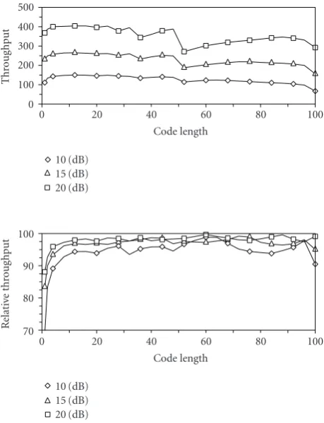
Figure3: ThroughputRpin bit per SS-OFDM symbol and relative
throughputRp/Rpin percent versus code lengthLt=L, for 1
sub-carrier, 3 received SNR{10, 15, 20}dB andΓ=6 dB.
Proof. It is simply proved using that ifx ∈Randx = x, then 2x−x−1< x− x. Thus
Rp=L Rp
L
+L2Rp/L−Rp/L−1
≤LRp L
+L2Rp/L−Rp/L−1
<Rp.
(12)
This inequality is true for allL∈N∗.
To illustrate Proposition 1, Figure 3 shows that the throughput Rp is an increasing function ofL, whereas the relative throughputRp/Rp converges to a value inferior to
100%. In this figure, the received SNR equals|hl,p|2(E/N0). This relative throughput is overall increasing withL, but can locally decrease due to the integer part operator.
We have introduced a rate upper-bound inSection 3.1
which gives a bound inRof a reliable rate inN. This bound is actually not a reachable rate in general as it can be viewed inFigure 3.Proposition 1then induces a new upper-bound well suited for reliable throughputs defined inN. LetRpbe
this new reliable upper-bound:
Rp=lim
L→∞ Rp
L = Rp
L
+ 2Rp/L−Rp/L−1. (13)
This upper-bound is then expressed in bit per OFDM sym-bol, and combining (11) with (13) it is clear thatRpis
inde-pendent ofL.
In terms of system performance,Figure 3shows that the time spreading exploits energy merging to improve the throughput. Indeed, the SS-OFDM throughput with Lt = L > 1 cannot be lower than that obtained with Lt = 1
which corresponds to the DMT system. The difference be-tween the throughputRpand the rate upper-boundRpis
re-duced which means that the energy merging translates into a compensation of the energy loss brought by the integer order modulations.
4.2. Frequency spreading
With 1D time spreading, the energy merging is realized be-tween the same time-subcarriers of several successive OFDM symbols. With 1D frequency spreading, the merging is in-stead realized between different subcarriers belonging to the same OFDM symbol. One SS-OFDM symbol is then reduced to one OFDM symbol, and the corresponding system would be an MC-CDMA (multicarrier coded division multiple ac-cess) system if the spreading component were used to realize multiple access between users [14]. In a general approach, the gains of the subcarriers over a subsetLpare not equal, that is, for all{l,l} ∈ L2
p andl=l,|hl,p|2= |hl,p|2. Then, the
rate upper-boundRpof pavementpis directly given by (7) without any simplifications, and the achievable throughput
Rpis simply expressed replacingRbyRpin (10).
This SS-OFDM system can benefit from carrier merg-ing to improved the system throughput even if the sub-carriers have different gains. For example, let P = 2, and |hi|2 = |hi|2(E/ΓN0), with|h1|2 =3.4 and|h2|2 =2.9. The DMT throughput corresponding to this two-subcarrier sys-tem equals 3 whereas the SS-OFDM throughput equals 4:
RDMT=
log2(1 + 3.4)+log2(1 + 2.9)=3,
RSS-OFDM=2×
log2(1 + 3.13)+ 0=4. (14)
The throughput gain is expected to be all the more im-portant than the amount of merged energies is high, that is, the frequency spreading factor increases. However, merging subcarriers with variable gains also leads to distortion within pavements. The ZF detector suppresses this distortion restor-ing the code orthogonality to the detriment of a noise level enhancement.
As it is shown inFigure 4over uncorrelated Rayleigh fad-ing channel of 100 subcarriers, the throughput overall in-creases with the code length but when the system exploits subcarriers with small received SNR, the carrier merging cannot compensate for the distortion. This is the case, for example, whenh30 or h40 are exploited with code lengths, respectively, equal to 30 and 40. For small code lengths, the throughput Rp is very far from upper-bound Rp, whereas
the differenceRp/Rp reaches a minimum for code lengths around 10–40 as evident from the relative throughput curve inFigure 4. Now focusing on the code throughputRp/K, it is
−20 0 20
0 20 40 60 80 100
Code length
0 35 70
0 20 40 60 80 100
Code length
50 75 100
0 20 40 60 80 100
Code length
0 1.5 3
0 20 40 60 80 100
Code length
Figure4: Received SNR in dB per subcarrier (a), throughputRpin bit per SS-OFDM symbol (b), relative throughputRp/Rpin % (c),
and code throughputRp/K(d) versus code lengthLf =Lover 100
subcarriers,Γ=6 dB.
code length. This means that the gain brought by the energy merging cannot compensate for the distortion.
A solution to mitigate the distortion is to use multi-ple elementary pavements thus reducing the spreading fac-tor while exploiting the highest possible number of subcar-riers. The corresponding system is commonly called spread-spectrum multi-carrier multiple access (SS-MC-MA) system [15]. Such a system needs to distribute subcarriers between the elementary pavements. The following proposition gives the optimal distribution that maximizes the throughputR.
Proposition 2. The optimal subcarrier subsetsLp,p∈[1;P], that maximize the throughputR=Pp=1Rpare such that for
allp=p, for alll∈Lp, for alll∈Lp, then|hl| ≥ |hl|.
Proof. We have basically shown that any subcarriers swap-ping between two subsetsLpandLp given by the
proposi-tion leads to a rate loss. This is done using simple derivaproposi-tion study of a sum of logarithm functions. The result obtained for two subsets is easily generalized forPsubsets.
A practical solution to make use ofProposition 2is to sort the subcarriers in descending order of power gain. The same result is obtained by symmetric with ascending order and also minimizes the distortion within each subset and maximizes the total throughputR. However,Proposition 2
0 100 200 300 400 500
0 20 40 60 80 100
Thr
o
ug
hpu
t
10 (dB) 15 (dB) 20 (dB)
Code length
70 80 90 100
0 20 40 60 80 100
R
elati
ve
thr
o
ug
hput
10 (dB) 15 (dB) 20 (dB)
Code length
Figure5: ThroughputRin bit per SS-OFDM symbol and relative throughputR/Rin percent versus code lengthLf = Lover 100
subcarriers, for 3 average SNR{10, 15, 20}dB, andΓ=6 dB.
which gives the unique optimal subcarrier distribution be-tween subsets forR∈R, only yields a suboptimal solution to theR ∈ Nmaximization problem. The optimal subset choice forR∈Rwould consist in finding the subcarriers that fully exploit the PSD in each subset. This optimal solution could be obtained following a subcarrier swapping approach after initial subcarrier distribution given by Proposition 2. The resulting algorithm would require a prohibitive inten-sive computation and the resulting rate gain would however not be sufficiently high to compensate for this complexity in-crease [9]. Therefore, we directly exploitProposition 2to dis-tribute subcarriers and then simply applyTheorem 2in each resulting pavement to maximizeRwith low complexity cost.
Figure 5 gives throughput R = pRp and relative
throughputR/Rof the SS-OFDM system over uncorrelated Rayleigh fading channel of 100 subcarriers. The average SNR is given by
Ehi2NE
0
= 1
100 100
i=1
hi2 E
N0.
(15)
All the 100 subcarriers are used if and only if the code length
120 140 160 180 200 220 240
0 20
40 60
80 100
Thr
o
ug
hput
(bit/OFDM
sy
m
bol)
0 20
40 60
80 100 Fre
q. spread.
Codelength
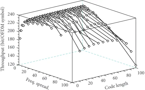
Figure 6: Throughput R/Lt versus code lengthL and frequency
spreading factorLf over 100 subcarriers, with an average SNR of
20 dB andΓ=6 dB.
obtained throughputs are lower than those obtained with lower code lengths. As inFigure 3, for small code lengths, the throughput Rp is very far from upper-bound Rp, whereas
this difference reduces for higher code lengths.Figure 5also shows thatLf =1 is not the optimal code length
configura-tion for throughput inN. However, the optimal configura-tion cannot be derived analytically.
Note that a more powerful equalizer such as minimum mean square error (MMSE) equalizer rather than ZF equal-izer could have been chosen to mitigate noise effect. How-ever,Proposition 2leads to subcarrier distribution that min-imizes channel distortion—and noise effect—within each subset. Then, ZF detection leads to throughputs very close to those obtained with MMSE equalizer. Furthermore, mathe-matical expressions obtained with MMSE have a form such that the studied optimization problem is not convex, whereas derivations with ZF are fairly simple and lead to a closed form solution to the optimization problem.
5. 2D SPREADING OPTIMIZATION
Merging the results inSection 4obtained with 1D time or frequency spreading, the throughput per elementary pave-ment writes with 2D time and frequency spreading
Rp=Llog2
1 +1
Γ
Lf Lf
l=1(1/hl,p2) E N0
, (16)
and applying (10) the total reliable throughput yields
R=
P
p=1
LRp L
+
P
p=1
L2Rp/L−Rp/L−1. (17)
Figure 6gives reliable throughputR/Lt per OFDM
sym-bol of the SS-OFDM system over uncorrelated Rayleigh fad-ing channel of 100 subcarriers. It firstly appears that the throughput increases withLt, that is, withLfor a fixed value ofLf, as already mentioned inFigure 3, and quickly reaches
its maximal value. On the other hand, for a fixed spreading
factorL, the throughput degrades for high values ofLfdue to
the increase of the frequency distortion. If the maximal time spreading factorLtis only limited byL, the highest
through-puts are obtained for small values ofLf and for high values
ofLt. Such configurations minimize the distortion within 2D pavements. The DMT throughput given byL=Lt=Lf =1 is around 130 bits per OFDM symbol, and is then easily out-performed by the SS-OFDM system.
It turns out that the optimal configuration, that is, code length, time, and frequency spreading factors, cannot be reached analytically for throughput inN, whereas the follow-ing proposition gives the optimal configuration inR.
Proposition 3. The throughputR=Pp=1Rpis maximal for
Lf =1.
Proof. The case of two subcarriers andLf ∈ {1; 2}is
ana-lyzed, the generalization being obvious. Letx,ybe the two normalized SNR per subcarrier. The throughputs write
R(Lf=1)=Ltlog2(1 +x) +Ltlog2(1 +y),
R(Lf=2)=Lt×2 log2
1 + 2
1/x+ 1/y
. (18)
The difference between these two functions shows that
R(Lf=2)≤R(Lf=1)for allLt.
The reliable rate upper-boundRpintroduced in Section 4.1remains valid usingRpdefined in (16) and (13).Rpthen
depends on the frequency spreading factorLf and, contrary
toR∈Rgiven byProposition 3, we cannot obtain any ana-lytical total reliable upper-boundR∈Nindependent ofLf.
6. MULTIUSER EXTENSION
In the single user context, the bit-loading algorithm applies
Theorem 2to perform bit, code, and energy allocation across the spectrum.
In the multiuser context different resource sharing strate-gies can be used (see, e.g., [16,17] and related references). We choose here to maximize the smallest throughput over all users, which is equivalent to maximize the total throughput of the system while ensuring equal rates between users. This strategy then sacrifices the overall performance of the system, measured as the sum rate of all active users. Maximizing this sum rate can be done at low computational complexity but favors only users with good channels and does not ensure bandwidth for all users. Maximizing the minimum through-put ensures minimum quality of services for all the active users, and then guarantees fairness between them.
To realize multiple access, we use a modified version of the subcarrier allocation algorithm proposed in [18]. LetNu
be the number of users,R(u)the throughput of useru, andBu the subset of subcarriers used by useruthat gathers several elementary pavements. Because of spectrum sharing between users following FDMA, we have for allu=u,Bu∩Bu= ∅.
For givenL,Lf, andLt, the proposed allocationAlgorithm 1
(1) Initialization
(a) Compute ∀u αu=R(u), with Bu=[1;N]
(b) Set ∀u R(u)=0, Bu= ∅
(2) While ∃u, Bu= ∅
(a) Find u=argminuαu|Bu= ∅
(b) For the foundu, find the best unused
Lf subcarriers (c) Update Bu, R(u), αu
(3) While there exists unused subcarrier
(a) Find u=argminuR(u)| ∃p, R(u) p >0
(b) For the foundu, find the best unused
Lf subcarriers (c) Update Bu, R(u).
Algorithm1
The modifications of the algorithm proposed in [18] are as follows (i) subcarriers are allocated to users by sets ofLf
subcarriers instead of being allocated one by one; (ii) theNu
first sets of subcarriers are assigned in step 2 with respect to a priority order among the users based on the achievable throughput of each user computed over all the available sub-carriers; and (iii) the user which cannot improve its rate is no more taken into account by the allocation procedure in step 3. The user with the smallestR(u)is being allocated at first, and then are the others. Of course step 3 is stopped when no more user can improve its throughput. Without condition in 3(a), the user with the worst channel would impose its throughput on all the other users, which would reduce the total throughput. Note that the structure of the algorithm is independent of the code lengthLand can be applied for
L=1 as well as forL >1.
7. SIMULATION RESULTS OVER POWER LINE CHANNELS
In practical systems, there isP = N/Lfelementary
pave-ments overNsubcarriers then
R=
P
p=1
Rp, R=
P
p=1
Rp, R= P
p=1
Rp, (19)
and in order to compare the performance of the systems, the throughputs are given in bit per OFDM symbol, that is, these throughputs areR/Lt,R, andR/Lt.
In this section, we present simulation results for the proposed adaptive SS-OFDM scheme and we compare the performance of the new scheme with the performance of DMT, that is, whenL = Lf = Lt = 1. The generated
SS-OFDM signal is composed of 2048 subcarriers transmitted in the band [0; 20] MHz, and 1880 subcarriers are used to transmit information data. ThenN = 1880 and the result-ing used bandwidth is [1.6; 20] MHz. The subcarrier spac-ing equals 9.765 kHz and a long enough cyclic prefix is used to overcome intersymbol interference. We assume that the
−60 −40 −20 0
Channel
tr
ansfer
function
(dB)
0 5 10 15 20
Frequency (MHz) #1
#2
#3 #4
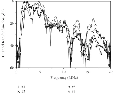
Figure7: Measured PLC channel transfer functions.
synchronization and channel estimation tasks have success-fully been treated. The used PLC responses, displayed in
Figure 7, have been measured in an outdoor residential net-work by the French power company Electricit´e de France
(EDF). We assume a background noise level of−110 dBm/Hz and the signal is transmitted with respect to a maximal PSD of−40 dBm/Hz. We consider that 2q-ary QAM are employed withq∈[2; 15] as in DSL specifications. Results are given for a target symbol error rate (SER) of 10−3corresponding to an SNR gapΓ=6 dB without channel coding. Some results are given versus channel attenuation which is related to maximal received SNR per subcarrier in the following way:
max SNR(dB)=70−Att(dB). (20)
From (7) withL=1, it comes that the DMT system needs a received SNR larger than 10.8 dB to transmit a minimal number of 2 bits per subcarrier, corresponding to a chan-nel attenuation lower than 59.2 dB. The following simulation results show that the SS-OFDM system can benefit from en-ergy merging to lower the required minimal received SNR and then improve the system range.
To perform bit-loading which needs CSI at the transmit-ter side, we assumed that the channel is constant over one SS-OFDM symbol, that is, overLtOFDM symbols. This
as-sumption cannot be valid for large values of time spread-ing. Furthermore, the SS-OFDM receiver have to memorize
Lt times the result of the FFT 2 K before any signal
process-ing. In order to limit this memory size and to assume con-stant channel over one SS-OFDM symbol, the maximal time spreading is then limited to 8.
7.1. Single-user case
Figures8and9give results with time spreading andLf =1, and with frequency spreading andLt = 1, respectively. In
70 80 90 100
R
elati
ve
thr
o
ug
hput
1 10 100
Time spreading factor 20 (dB)
40 (dB) 50 (dB)
60 (dB)
70 (dB)
Figure8: Relative throughputR/(LtR) in percent of SS-OFDM sys-tem withLf =1 versus code length, over PLC channel no. 1 and for
six channel attenuations{20, 30, 40, 50, 60, 70}dB.
25 5e3 1e4
Thr
o
ug
hpu
t
20 30 40 50 60 70
Channel attenuation (dB)
0 50 100
F
req.
spr
eading
20 30 40 50 60 70
Channel attenuation (dB)
90 95 100
R
elati
ve
thr
o
ug
hput
20 30 40 50 60 70
Channel attenuation (dB) 16
64 188
Figure9: Maximal throughput max(R) in bit per SS-OFDM sym-bol, corresponding code length, and relative throughputR/max(R) for three code lengthsLf = {16, 64, 188}of SS-OFDM withLt=1
versus channel attenuation in dB, over PLC channel no. 1.
Figure 8shows that the higher the channel attenuation is, the larger the time spreading factor should be to achieve a given percent of the reliable upper-boundR. With chan-nel attenuation of 70 dB, the time spreading factor must be higher than 100 to reach 90% of the reliable throughput upper-bound. For lower channel attenuations, that is, higher
1 2 3 4 5 6 7 8
T
ime
spr
eading
fact
or
20 40 60 80 100
50 (dB) 40 (dB) 30 (dB)
Figure 10: Time and frequency spreading configurations of SS-OFDM system which lead to at least 99.5% of the maximal value of the reliable rate upper-boundR, over PLC channel no. 1 and for three channel attenuations{30, 40, 50}dB.
received SNR, shorter time spreading factors are sufficient to reach a high percentage of the bound. When the chan-nel attenuation increases, the energy per subcarrier and per OFDM symbol decreases and drops under values for which no more bits can be transmitted for an increasing number of subcarriers. To transmit bits over these zeroed subcarri-ers larger time spreading factors must be used to merge more OFDM symbols.
Since none analytical reliable upper-bound can be de-rived, as already mentioned inSection 4.2, the optimal fre-quency spreading factor that maximizes the throughput is worked out through simulation search. Figure 9 then shows the maximal throughput and the corresponding fre-quency spreading factor obtained for channel attenuations in [20; 70] dB. The optimal frequency spreading is Lf ∈
[36; 96] with an average value around 52. When comparing the throughput of fixed frequency spreading configurations with the optimal throughput for each channel attenuation, it appears that all the frequency spreadings, except very high
Lf, give throughputs up to 99% of the maximal throughput for low channel attenuations. For high channel attenuations, the system cannot merge enough subcarriers with lowLf,
and cannot compensate for the channel distortion with very highLf in order to improve the throughput. For these high
channel attenuations, the optimal frequency spreading factor is around 64.
Figure 10 gives results with both time and frequency spreadings, that is, with 2D spreading. The reliable rate upper-bound R is frequency spreading dependent. In or-der to work with a frequency spreading independent upper-bound, the maximal rate upper-bound is computed over all the possible time and frequency spreading configurations,
0 5e3 1e4
Thr
o
ug
hpu
t
DMT
Reliable upper bound
20 30 40 50 60 70
Channel attenuation (dB)
60 70 80 90 100
R
elati
ve
thr
o
ug
hput
4×94 6×40
8×2 1×1
20 30 40 50 60 70
Channel attenuation (dB)
Figure 11: Throughput of DMT and SS-OFDM maximal reli-able upper-bound in bit per OFDM symbol, relative through- put R/(LtR) of SS-OFDM systems in percent versus channel
attenua-tion in dB, with configuraattenua-tions{Lt,Lf} ∈ {{4, 94};{6, 40};{8, 2}; {1, 1}}.
that lead to at least 99.5% of this maximal bound. The num-ber of these configurations decreases when the channel at-tenuation increases. For example, this number of configura-tions is equal to 285, 155, and 13 for channel attenuation, re-spectively, equal to 30, 40, and 50 dB. With 50 dB of channel attenuation, most of the optimal configurations use a time spreading factor close to the maximal available one, that is,
Lt = 8. It is important to note that there exist several con-figurations that lead to throughputs very close to the maxi-mal rate upper-bound. In practice, it is then possible to fix in advance, that is, not in real time but as of the system de-sign, a subset of configurations that yield performance close to the optimal. This approach reduces the number of config-urations that the system has to compare in real-time.
Figure 11gives the throughput of the DMT system and the optimal rate upper-bound of the SS-OFDM system, and compared the throughputs of four SS-OFDM configurations relative to this upper-bound. The DMT throughput, corre-sponding to the SS-OFDM system withL=Lt =Lf =1, is easily improved by the SS-OFDM system. The DMT system cannot reach 60% of the reliable upper-bound for channel attenuations higher than 55 dB, whereas the SS-OFDM sys-tem with{Lt,Lf} ∈ {{4, 94};{6, 40}}can reach at least 90%
of this upper-bound even for a channel attenuation equals to 70 dB. Let us recall that for this channel attenuation the received SNR per subcarrier is lower or equal to 0 dB. The SS-OFDM system is then able to transmit information even
0 1k 2k 3k
Me
an
th
ro
u
gh
p
u
t
SS-OFDM DMT
20 30 40 50 60 70
Channel attenuation (dB)
1 4 8
T
ime
spr
eading
20 30 40 50 60 70
Channel attenuation (dB)
0 100 200
F
req.
spr
eading
20 30 40 50 60 70
Channel attenuation (dB)
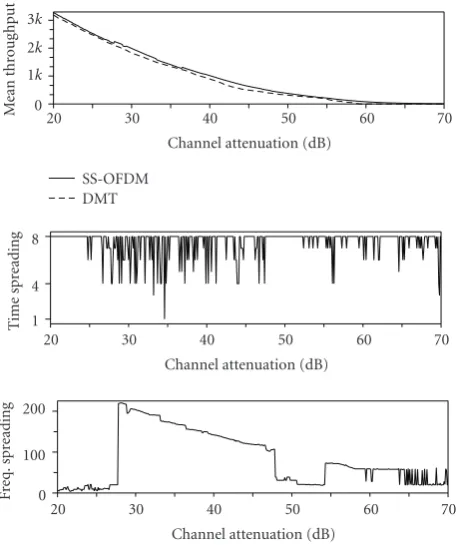
Figure12: Average throughput per user of DMT and SS-OFDM, and corresponding{Lt,Lf}SS-OFDM configuration, versus
chan-nel attenuation.
if the signal is under the noise level, whereas this is impossi-ble with the DMT system. The SS-OFDM system can exploit subcarriers with received SNR equal to 10.8−10 log10LdB to transmit the lower number of bits which is 2, that is, channel attenuation equals to 59.2 + 10 log10LdB.
7.2. Multiuser case
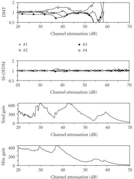
In the multiuser case, the time and frequency resource is shared by the users with FDMA, whereas the SS is used to multiplex the data of each user as in the single user case. The simulation results are given for the four power line chan-nel responses displayed inFigure 7. Each user transmits in-formation over its own channel. Let us recall that the bit-loading algorithm proposed inSection 6aims at maximizing the smallest throughput over all users, which ensures mini-mal differences between their throughputs. Note that this al-gorithm is appropriate whatever the length code L, in par-ticular forL=1, that is, for DMT. In order to have flexibil-ity sharing the subcarriersLf ≤235 which means that the minimal number of elementary pavements per user is 2. The maximal value ofLtis still 8.
0.5 1 2
DMT
20 30 40 50 60 70
Channel attenuation (dB) #1
#2
#3 #4
0.5 1 2
SS-OFDM
20 30 40 50 60 70
Channel attenuation (dB)
0 300 600
To
ta
l
ga
in
20 30 40 50 60 70
Channel attenuation (dB)
0 200 400
M
in.
gain
20 30 40 50 60 70
Channel attenuation (dB)
Figure13: Relative throughput dispersion per user for DMT and SS-OFDM, total throughput gain, and gain of minimum user’s throughput of SS-OFDM compared to DMT, versus channel atten-uation.
exhaustive search overLt ≤8 andLf ≤235. The
through-puts are expressed in bit per OFDM symbol, and 1 kbyte per OFDM symbol corresponds to a mean throughput per user of 9.765 Mbps and a total throughput of 39 Mbps. For all the channel attenuations, the average throughput per user with SS-OFDM is higher than the average throughput per user with DMT, even if the multiuser bit-loading algorithm is not designed to maximize the total system throughput. The opti-mal time spreading factor is equal to the maxiopti-mal possible value except for some particular channel attenuations and contrary to the results obtained in the single user case with
Lf = 1 (seeFigure 8) for which the optimal time
spread-ing factor is always the maximal possible one. As for the fre-quency spreading factor,Figure 12shows thatLf is overall
decreasing with the channel attenuation from 30 dB but ex-hibits a strong dispersion of the values,Lf ∈ [4; 220], and contrary to the single-user case withLt = 1 (seeFigure 9)
for which an average frequency spreading factor around 52 is obtained. Eventually, we cannot conclude that there exists a unique pair{Lt,Lf}that yields the optimal configuration.
Figure 13gives the throughput dispersion of each user which is evaluated as the ratio between the individual throughput and the average throughput. These values are given for the DMT system and for the SS-OFDM system
with the optimal configurations given inFigure 12. The to-tal gain is the difference between the SS-OFDM and DMT total throughputs. The minimum gain is the difference be-tween the SS-OFDM and DMT minimal throughputs among users. As evident from the obtained results, the SS-OFDM system provides a lower throughput dispersion between users than DMT. The adaptive SS-OFDM system has in fact much more variable parameters than DMT, which allows to bet-ter answer to the resource sharing problem, and especially minimize the throughput dispersion. Now focusing on the throughput gain, the total and the minimal user throughputs are improved with SS-OFDM. In the figure, a gain of 300 bits per OFDM symbol corresponds to a gain of 2.9 Mbps. Then, for channel attenuation equals to 50 dB, the minimum throughput obtained with {Lt,Lf} = {8, 31} is increased
by 779 bps, that is, 27%, and the corresponding total gain is 20%. For lower channel attenuations, for example 30 dB, the minimum throughput is increased by 23%, and the total throughput by 9%. For all the channel attenuations the gain of the minimum throughput is higher than 11.8%.
Complementary simulations show that there exist 175 configurations that give a gain of at least 10% for all the channel attenuations, and 449 configurations for which SS-OFDM outperforms DMT for all the channel attenuations. Then, there is a great choice of configurations that allow to achieve higher rates than DMT. To simplify this choice,
Table 1proposes optimal spreading configurations for some ranges of channel attenuations. Note that all users can trans-mit low rate information up to 83 dB of channel attenuation with SS-OFDM, whereas DMT needs channel attenuations lower than 58 dB to transmit information for all users. For example, for the largest range, that is, channel attenuation in [20; 83], the optimal configuration is {Lt,Lf} = {8, 5} yielding a minimum throughput gain of 11.8% (the min-imal value is obtained for 20 dB of channel attenuation). A minimum gain of 26.4% is reached for channel attenua-tions higher than 50 dB. These results show that it is possible in practice to select a small number of interesting configu-rations depending on channel attenuation ranges to reach throughputs higher than those obtained with DMT. More generally, it is possible to pick and choose a set of interest-ing configurations accordinterest-ing to all the practical transmission scenarios that will be used to design the modem. The online modem will only have to select in real time the configuration adapted to its transmission link.
8. CONCLUSION
Table 1: SS-OFDM optimal configuration and minimum user’s throughput gain versus channel attenuation.
Chan. at. Opt. config. Min. user’s gain
(dB) (Lt×Lf) (%)
20–83 8×5 11.8
30–83 8×15 15.0
20–30 8×5 11.8
30–40 8×191 18.7
40–50 8×38 23.3
50–58 8×31 26.4
into energy merging in the time and frequency domains that leads to an increase of the throughputs compared with the classical DMT approach. This gain is understood as a reduc-tion of the quantificareduc-tion loss due to the finite-order mod-ulations. Well-chosen spreading factors lead to minimum user throughputs improved by at least 11.8% for low chan-nel attenuations, and more than 23.3% for chanchan-nel attenua-tions higher than 40 dB. Among the large number of possible spreading configurations, it is possible to establish a limited number of system configurations adapted to pratical trans-mission scenarios, and chosen in real time by the online mo-dem.
ACKNOWLEDGMENTS
The authors would like to thank the anonymous reviewers for their insightful comments. This paper has been presented in part at the IEEE Global Communications Conference, San Francisco, 2006, and at the IEEE International Symposium on Spread Spectrum Techniques and Applications, Manaus-Amazomn, 2006.
REFERENCES
[1] L. H.-J. Lampe and J. B. Huber, “Bandwidth efficient power line communications based on OFDM,”International Journal of Electronics and Communications, vol. 54, no. 1, pp. 2–12, 2000.
[2] E. Del Re, R. Fantacci, S. Morosi, and R. Seravalle, “Compari-son of CDMA and OFDM techniques for downstream power-line communications on low voltage grid,”IEEE Transactions on Power Delivery, vol. 18, no. 4, pp. 1104–1109, 2003. [3] J. Cioffi, “A multicarrier primer,” Tech. Rep. T1E1.4/91–157,
ANSI, Washington, DC, USA, committee contribution, 1991. [4] G. D. Forney Jr. and L.-F. Wei, “Multidimensional
constel-lations—part I: Introduction, figures of merit, and generalized cross constellations,”IEEE Journal on Selected Areas in Com-munications, vol. 7, no. 6, pp. 877–892, 1989.
[5] O. Isson, J.-M. Brossier, and D. Mestdagh, “Multi-carrier bit-rate improvement by carrier merging,”Electronics Letters, vol. 38, no. 19, pp. 1134–1135, 2002.
[6] S. Mallier, F. Nouvel, J.-Y. Baudais, D. Gardan, and A. Zeddam, “Multi-carrier CDMA over copper lines—Comparison of per-formances with the ADSL system,” inProceedings of the 1st In-ternational Workshop on Electronic Design, Test & Applications (DELTA ’02), pp. 450–452, Christchurch, New Zealand, Jan-uary 2002.
[7] M. Crussi`ere, J.-Y. Baudais, and J.-F. H´elard, “adaptive linear precoded DMT as an efficient resource allocation scheme for power-line communications,” in Proceedings of IEEE Global Telecommunications Conference (GLOBECOM ’06), pp. 1–5, San Francisco, Calif, USA, November 2006.
[8] M. Crussi`ere, J.-Y. Baudais, and J.-F. H´elard, “Improved throughput over wirelines with adaptive MC-DS-CDMA,” in Proceedings of the 9th IEEE International Symposium on Spread Spectrum Techniques and Applications, pp. 143–147, Manaus, Amazon, Brazil, August 2006.
[9] M. Crussi`ere, J.-Y. Baudais, and J.-F. H´elard, “Adaptive spread-spectrum multicarrier multiple-access over wirelines,” IEEE Journal on Selected Areas in Communications, vol. 24, no. 7, pp. 1377–1388, 2006.
[10] G. B. Giannakis, P. A. Anghel, and Z. Wang, “Generalized multicarrier CDMA: Unification and linear equalization,” EURASIP Journal on Applied Signal Processing, vol. 2005, no. 5, pp. 743–756, 2005.
[11] A. S. Hedayat, N. J. A. Sloane, and J. Stufken,Orthogonal Ar-rays: Theory and Applications, chapter 7, Springer, New York, NY, USA, 1999.
[12] S. Hara and R. Prasad, “Overview of multicarrier CDMA,” IEEE Communications Magazine, vol. 35, no. 12, pp. 126–133, 1997.
[13] S. Kondo and L. Milstein, “On the use of multicarrier direct se-quence spread spectrum systems,” inProceedings of IEEE Mil-itary Communications Conference (MILCOM ’93), vol. 1, pp. 52–56, Boston, Mass, USA, October 1993.
[14] N. Yee, J.-P. Linnartz, and G. Fettweis, “Multi-carrier CDMA in indoor wireless radio networks,” inProceedings of the In-ternational Symposium on Personal, Indoor and Mobile Ra-dio Communications (PIMRC ’93), pp. 109–113, Yokohama, Japan, September 1993.
[15] S. Kaiser and K. Fazel, “A flexible spread-spectrum multi-carrier multiple-access system for multi-media applications,” inProceedings of the 8th IEEE International Symposium on Per-sonal, Indoor and Mobile Radio Communications (PIMRC ’97), vol. 1, pp. 100–104, Helsinki, Finland, September 1997. [16] C. Y. Wong, R. S. Cheng, K. B. Letaief, and R. D. Murch,
“Mul-tiuser OFDM with adaptive subcarrier, bit, and power allo-cation,” IEEE Journal on Selected Areas in Communications, vol. 17, no. 10, pp. 1747–1758, 1999.
[17] T. Sartenaer, L. Vandendorpe, and J. Louveaux, “Balanced ca-pacity of wireline multiuser channels,”IEEE Transactions on Communications, vol. 53, no. 12, pp. 2029–2042, 2005. [18] W. Rhee and J. M. Cioffi, “Increase in capacity of
mul-tiuser OFDM system using dynamic subchannel allocation,” inProceedings of the 51st IEEE Vehicular Technology Conference (VTC ’00), vol. 2, pp. 1085–1089, Tokyo, Japan, May 2000.
Jean-Yves Baudaisreceived the M.S. degree, and Ph.D. degree in electrical engineering from the National Institute of Applied Sci-ences of Rennes (INSA), France, in 1997 and 2001, respectively. Since 2002, he has been working as a CNRS researcher (French National Centre for Scientific Research) in the Institute for Electronics and Telecom-munications of Rennes (IETR). His current research focuses on transmitter and receiver
Matthieu Crussi`erereceived the M.S. and Ph.D. degrees in electrical engineering from the National Institute of Applied Sciences (INSA), France, in 2002 and 2005, respec-tively. During his Ph.D. degree, he was with the Electronics and Telecommunica-tions Institute of Rennes (IETR), where he worked on the optimization of high bit rate power line communications. Since 2005, he has been an Assistant Professor in the