Volume 2010, Article ID 295016,8pages doi:10.1155/2010/295016
Research Article
Improvement of Adaptive Cruise Control Performance
Shigeharu Miyata,
1Takashi Nakagami,
2Sei Kobayashi,
2Tomoji Izumi,
2Hisayoshi Naito,
2Akira Yanou,
3Hitomi Nakamura,
1and Shin Takehara
11Department of Intelligent Mechanical Engineering, Faculty of Engineering, Kinki University, 1, Takaya-Umenobe,
Higashihiroshima, Hiroshima 739-2116, Japan
2Vehicle Development Division, Vehicle System Development Department, Mazda Motor Corporation, 3-1,
Shinchi, Aki-Fuchu, Hiroshima 730-8670, Japan
3Department of Intelligent Mechanical Systems, Graduate School of Natural Science and Technology,
Okayama University, 3-1-1, Tsushima-naka, Kita-ku, Okayama 700-8530, Japan
Correspondence should be addressed to Shigeharu Miyata,miyata@hiro.kindai.ac.jp
Received 14 October 2009; Revised 7 June 2010; Accepted 24 August 2010
Academic Editor: Hossein Pishro-Nik
Copyright © 2010 Shigeharu Miyata et al. This is an open access article distributed under the Creative Commons Attribution License, which permits unrestricted use, distribution, and reproduction in any medium, provided the original work is properly cited.
This paper describes the Adaptive Cruise Control system (ACC), a system which reduces the driving burden on the driver. The ACC system primarily supports four driving modes on the road and controls the acceleration and deceleration of the vehicle in order to maintain a set speed or to avoid a crash. This paper proposes more accurate methods of detecting the preceding vehicle by radar while cornering, with consideration for the vehicle sideslip angle, and also of controlling the distance between vehicles. By making full use of the proposed identification logic for preceding vehicles and path estimation logic, an improvement in driving stability was achieved.
1. Introduction
The number of traffic accidents and injuries continues to increase year by year, and annual traffic fatalities in Japan remain at over 7000. Under these conditions, there is an urgent need for technologies which can mitigate the serious damage caused by car accidents, as well as prevent the accidents themselves. Some members of this study have played active roles in a study group for the Advanced Safety Vehicle (ASV), a project conducted by the Japanese Ministry of Land, Infrastructure, Transport and Tourism, and are involved with ASV research and development. This study group has proposed and studied safety technologies such as Adaptive Cruise Control (ACC) and Precrash Safety Systems [1–7]. Some of these technologies have already been put into practical use.
An ACC system maintains the vehicle at the speed set by the driver, and when it detects a preceding vehicle travelling at a slower speed than the driver’s vehicle, it controls the vehicle speed to match the speed of the preceding vehicle. It also performs following control to maintain the level of
distance between vehicles which was set by the driver (a distance proportional to the vehicle speed). There has been past research for ACC systems aimed at designing a vehicle following distance control system using linear approximation and linear control logic [8]. However this research has not succeeded in producing natural vehicle behavior that meets the drivers’ expectations. In addition, while a method for following a preceding vehicle on curves has been proposed [9] based on the following distance measured by stereo image processing and on the relative vehicle speed, this method is limited to following distances in the range of 4 m–22 m, and it is not suitable for maintaining the following distance of approximately 100 m that is needed for expressway driving.
attempts other than this paper have been found at creating an ACC system with following control that incorporates consideration of the vehicle sideslip. Our research team has already submitted a patent application for this concept [13]. This paper describes the Adaptive Cruise Control system (ACC), a system which reduces the driving burden on the driver. The ACC system primarily supports the four driving modes on the road that are described in Section 2.1, and controls the acceleration and deceleration of the vehicle in order to maintain a set speed or to avoid a collision. The key to achieving intelligent ACC control is the method used to detect and follow the preceding vehicle.
The use of obstacle detection equipment, which detects the preceding vehicle by means of millimeter wave radar, is already well established [14–18]. When the obstacle detection equipment detects a vehicle (obstacle) in the path ahead of the driver’s vehicle, the turning radius of the driver’s vehicle (calculated based on the values from the yaw rate sensor and steering angle sensor) is used to estimate the position of the preceding vehicle after the next radar scan. The system then judges whether or not the estimated position of the preceding vehicle matches the position detected after the radar scan. As long as the turning radius of the driver’s vehicle does not change significantly between the radar scans, then calculating the amount of offset of the detected preceding vehicle from its path center line allows the future position of the preceding vehicle to be easily estimated. In particular when the speeds of the driver’s vehicle and the preceding vehicle are approximately the same, the amount of this offset can be assumed to be unchanging between radar scans, making it possible to easily predict the position of the preceding vehicle. However as described above, on expressways where the vehicles are travelling at high speed, if there is a curve where the turning radius of the driver’s vehicle changes between radar scans, the sideslip that occurs when the vehicle corners causes the amount of offset from the preceding vehicle path center line to change. As a result, it becomes impossible to accurately estimate the position of the preceding vehicle, and the driver’s vehicle accelerates, producing a potentially dangerous situation.
This ACC system that incorporates consideration of the sideslip angle makes it possible for one vehicle to reliably follow the preceding vehicle by performing the following two operations. First, the system estimates the path (the radius of curvature of the path center line) by determining the cornering radius of the vehicle based on the detected yaw rate, steering wheel angle, and vehicle velocity. Second, the system judges whether or not the current detected vehicle is the same as the previous detected vehicle by comparing the position of the detected vehicle with a position that is estimated based on the calculated offset from the center line of the path each time a radar scan occurs. Usually, the radius of curvature of the path center line is assumed to be unchanged during the period between radar scans. However, in cases of curves near an entrance or exit, the radius of curvature of the path actually does change during the period between radar scans. In these cases, if the offset is assumed to be unchanged, the radar fails to lock onto the preceding vehicle. Therefore, because the position of the preceding
vehicle relative to the driver’s own vehicle is influenced by the sideslip of vehicle, the offset needs to be corrected at each radar scan based on the most recent detected cornering radius.
For the following operation, ACC performs control in order to maintain a constant distance. However, for example, when the preceding vehicle is traveling close to the second vehicle ahead, and if the preceding vehicle brakes and accelerates suddenly and repeatedly (jerky motions), the driver’s own vehicle is forced to perform the same jerky motions. As a result, such a system cannot be expected to provide good ride quality and a feeling of safety. Therefore, it is necessary to change from velocity control which maintains a constant distance between the driver’s vehicle and the preceding vehicle to velocity control which maintains a constant distance between the driver’s vehicle and the second vehicle ahead. In this way, even if the preceding vehicle performs repeated jerky motions, the driver’s own vehicle is not forced to perform sudden braking and acceleration. This results in a definite improvement to the ride quality and the feeling of safety.
From the above points of view, this paper proposes a more accurate method of detecting the preceding vehicle by radar, and of controlling the distance between vehicles. This proposal also for the first time includes consideration of the vehicle sideslip angle. These methods are expected to result in improved driving stability.
Section 2 of this paper describes the ACC system configuration. Section 3 explains the functions related to velocity control. Evaluation for the ACC system based on the experiment results and conclusions are presented in Section 4.
2. ACC System Configuration
2.1. Primary ACC Modes. The ACC system supports four control modes, which are described below and shown in Figure 1.
(1)Constant velocity control: when there are no vehicles straight ahead, or when there is a large distance between the driver’s vehicle and the preceding vehi-cle, the system maintains a constant vehicle velocity. (2)Deceleration control: when a vehicle traveling ahead at
a slower speed is detected, the system uses the throttle to decelerate the driver’s vehicle. If this deceleration is insufficient, the system uses the brake to decelerate the vehicle.
(3)Following control: when the driver’s vehicle is fol-lowing behind the preceding vehicle, the system controls the throttle and brake so that the time interval between the vehicles (which corresponds to a distance between the vehicles that is proportional to the velocity of the driver’s vehicle) is the time which was set by the driver.
60 km/h ↓
↓
↓ ↓
80 km/h
80 km/h 60 km/h
60 km/h 60 km/h 50 km/h
Set velocity
80 km/h 60 km/h 50 km/h
(1
)C
o
n
st
an
tv
el
o
ci
ty
oper
ation
(2)
D
ec
eler
ation
cont
rol
(3)
F
ollo
w
ing
op
er
at
ion
(4
)
A
cce
le
ra
ti
o
n
co
n
tro
l
Figure1: Four modes supported by the ACC system.
by the driver, and then maintains a constant velocity. Furthermore, when the driver’s vehicle approaches a vehicle ahead of it without slowing down enough, an alert buzzer and display prompt the driver to apply the brakes or take other appropriate action.
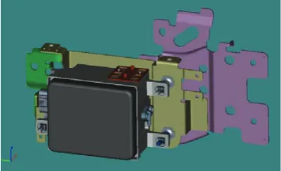
2.2. System Configuration. Figure 2shows the ACC system configuration and unit layout in a vehicle. This configuration includes the existing Auto Speed Control (ASC), Dynamic Stability Control (DSC), Millimeter Wave Radar used to detect objects ahead, ACC Electrical Control Unit (ACC ECU) used to calculate control values for the engine and brake, Distance Setting Switch used to set a time interval for following the preceding vehicle (in order to maintain a constant distance), and Indicator/Display which informs the driver of the control mode.Figure 3shows the part layout for the sensors, ECU, and other components. For brake control, the DSC brake actuator function is extended to perform feedback control, so that the deceleration demanded by the driver is delivered. For engine control, the vehicle velocity set by ACC is transmitted to the vehicle velocity control section
Millimeter wave radar Distance setting switch
Brake lamp
Cruise control switch Electronic throttle valve
Wheel speed sensor
Brake pressure sensor Brake actuator Steering angle sensor
Indicator / display Meter BCM ECU DSC ECU PCM ECU
DSC ASC
CAN CAN
Yaw rate/lateral G sensor
ACC ECU
Figure2: System configuration.
ACC ECU
Brake pressure sensor
Wheel speed sensor Steering
angle sensor
Yaw rate/ lateral G sensor DSC
Brake lamp PCM Cruise control switch
Distance setting switch Millimeter
wave radar
Speedmeter
BCM
Figure3: ACC unit layout.
of the existing ASC, and the system then controls the vehicle velocity so as to follow the vehicle preceding it.
Values from the wheel speed sensor and yaw rate/lateral G sensor are transmitted to the DSC ECU, and values for the vehicle velocity and other items set from the operation switches are transmitted to the PCM ECU. Furthermore, the signals of both ECUs are collected at the ACC ECU via CAN (Control Area Network). The transmissions between the Millimeter Wave Radar and the ACC ECU are carried out via CAN. In addition, when brake control is performed, ACC controls the relay between the brake pedal switch and the brake lamp in order to turn on the brake lamps.
Figure4: View of the Millimeter Wave Radar.
Table1: Millimeter Wave Radar performance.
Detection range
Max 150 m
Min 2 m
Resolution 0.1 m
Range rate
Max 200 km/h
Min −200 km/h
Resolution 0.36 km/h
Azimuth angle Area ±7.5 deg
Resolution 0.1 deg
Data rate 100 msec
2.3. Millimeter Wave Radar. Figure 4shows an external view of the Millimeter Wave Radar used in this system. The frequency of the Millimeter Wave Radar is 76 to 77 GHz. An FMCW system is used, allowing the distance between vehicles and the relative velocity to be simultaneously measured with very high precision. In order to detect the horizontal angle, a mechanical scan system is used, in which the antenna and millimeter wave transmitter/receiver are panned back and forth to the right and left sides by a motor. This system yields a relatively high angle resolution. In addition, the thickness of this radar has been reduced to 70 mm, which makes it possible to install it inside the bumper, despite the mechanical scanning. The specifications of the millimeter wave radar are shown inTable 1.
3. ACC ECU
The main functions of the ACC system are selection of the preceding vehicle and control of the distance between the vehicles.Figure 5shows a block diagram of the control logic. The ACC ECU selects the preceding vehicle to follow by utilizing the information (distance and relative velocity) transmitted by the Millimeter Wave Radar. The system then controls the acceleration and deceleration of the vehicle based on control values such as the target vehicle velocity and the target acceleration/deceleration.
3.1. Selection of the Preceding Vehicle during Cornering. The Millimeter Wave Radar is used to detect the vehicles traveling ahead of the driver’s vehicle. When the road is straight, the preceding vehicle can be easily identified as the vehicle
traveling ahead on the same path as the driver’s vehicle. However, it becomes more difficult to identify the preceding vehicle when there are curves in the road. As shown in Figure 6, when three vehicles are traveling ahead of the driver’s vehicle at a curve in the road, it is first necessary to determine which vehicle is on same path as the driver’s vehicle and which vehicles are not on the same path. Then the vehicle to be followed can be correctly identified.
The system judges whether the object detected by the radar is a relative static object or moving object by comparing the velocities of the driver’s vehicle and detected vehicle. If the preceding vehicle is traveling at a speed that is approximately the same, that vehicle is considered to be a relative static object.
At the same time, the path (with radius of curvatureR) is estimated by determining the cornering radius of the driver’s vehicle based on the detected yaw rate, steering wheel angle, and vehicle velocity.
The system judges whether or not the current detected vehicle is the same as the previous detected vehicle each time a radar scan occurs. This judgment is performed by comparing the position of the detected vehicle with the estimated position. Therefore the offset from the center line of the path is recalculated at each radar scan in order to estimate a new position for the detected vehicle after it has moved.
Usually, the radius of curvatureRof the path center line is assumed to be unchanged during the period between radar scans. However, in cases when the vehicle is on a curve near an entrance or exit, the path radius of curvature actually does change between radar scans. If the sideslip is assumed to be unchanged, the system fails to lock onto the target vehicle. Therefore, because the relative position of the preceding vehicle to the driver’s vehicle is influenced by the sideslip of the vehicle, the offset needs to be corrected at each radar scan based on the most recent detected cornering radius.
3.2. Basic Logic. The system estimates the radius of curvature for the path of the driver’s vehicle based on the yaw rate and vehicle velocity. When the vehicle is cornering, the relationship among the velocityV, the yaw rater, and the cornering radiusRis obtained as follows:
R=V
r . (1)
Figure 7shows the geometric relationships between the driver’s vehicle and the vehicle immediately preceding it. The arc of radiusRis the traffic lane of the driver’s vehicle. If the offset ε, which is the distance between the traffic lane and the preceding vehicle, is within a certain range, the preceding vehicle is determined to be traveling on the same path. Here, if the distance to the vehicle immediately preceding is d, and the irradiation angle of the radar is θ, the following relationship can be derived:
{R−(ε−dθ)}2=
dr,vr Vt vr
vL
Target headway distance generator
Selection leading
vehicle
Target acceleration/ deceleration generator
Vehicle model Feedback Plant compensator
Feedback compensator
Vr
Vr dL
dt
+ − Gt Gc
Gt
Gr
Vc
PCM DSC ACC C/M
Figure5: Control block diagram.
FOV of radar
Predicted lane
Mazda MPV
Detected vehicle Other objects
out side of road
- Detect several objects by radar - Predict own lane by Yaw rate
sensor and vehicle velocity. - Decide target vehicle based on
the Predicted lane and position moving object
Obstacle detection and path estimation Leading vehicle
Figure6: Detection of preceding vehicle and estimation of path.
Assuming that (ε−dθ) is sufficiently smaller than the radius R, the offsetεcan be derived as follows:
ε=dθ+ d 2
2R=d
θ+ d 2R
. (3)
3.3. Introduction of the Sideslip Angle. In actual cases when a vehicle is traveling at a certain velocity on the road, a sideslip angle occurs at the vehicle during cornering. When the traffic lane curves, this sideslip result in a deviation in the range of irradiation. Correcting the range of irradiation can be expected to improve the offset accuracy.
A dynamic model of the vehicle shown inFigure 8can be expressed as follows [12]:
2Kf +Kr
β+
mV+ 2 V
lfKf−lrKr
r=2Kfδ,
2lfKf −lrKr
β+ 2 V
l2
fKf +l2rKr
=2lfKfδ.
(4)
R
R θ
ε
dθ
d
Figure7: Position of preceding vehicle during cornering without
considering the sideslip angle.
Using (4), the sideslip angle can be calculated as follows:
β=
1−m
2l lf
lrKrV 2 lr
Rear tire
r: Yaw rate Front tire
C.G.
δf β
lr
lf
Figure8: Two-wheel model of a vehicle.
Table2: Vehicle system parameters.
m Vehicle mass
V Vehicle speed
C.G. Center of gravity
lf Distance between front axle and C.G.
lr Distance between rear axle and C.G.
Kf Front cornering power
Kr Rear cornering power
r Yaw rate
β Sideslip angle
δf Tire angle
From the relationship between the sideslip and the cornering radius shown in Figure 9, the amount of center travelLcan be obtained as follows:
L=Rβ=
1−m
2l lf
lrKrV 2 lr
l. (6)
Based on the relationships shown inFigure 9and considering the sideslip element, the following relationship can be expressed in nearly the same way as inFigure 7:
R−ε−dθ+β2=R2−d2. (7)
Assuming that (ε−d(θ+β)) is sufficiently smaller than the radiusR, the offsetεcan be obtained as follows:
ε=dθ+β+ d 2
2R=d
θ+d+ 2L 2R
.
(8)
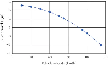
The absolute amount of center travelLis proportional to the square of the vehicle velocity as shown in (6). Therefore, hereLcan be expressed as follows:
L=aV2+b. (9)
Parametersa andb are then identified by using the actual experiment data.Figure 10shows the relationship between the vehicle velocityVand the amount of center travelL.
Figure 11shows the relationship between the amount of correctiondβand the cornering radiusR. It can be seen that
L d(θ+β)
R
R ε
d θ
β
β
Figure 9: Position of preceding vehicle during cornering, with
consideration for the sideslip angle.
−2
−1 0 1 2 3 4
0 20 40 60 80 100 Vehicle velocity (km/h)
Center
tr
av
el
L
(m
)
Figure10: Relationship between amount of center travelLand the
vehicle velocity.
the smaller the cornering radius is, the larger the amount of correction becomes.
The system judges whether the objects detected by the millimeter wave radar are relative static objects, which include a preceding vehicle traveling at the same speed, or relative moving objects. This judgment is performed by using the velocity of the objects relative to the velocity of the driver’s vehicle. The driving path for the driver’s vehicle is estimated from the current vehicle conditions such as the vehicle velocity, steering angle, and yaw rate. The target preceding vehicle on the estimated path is selected based on the position of the preceding vehicle relative to the estimated driving path.
InFigure 12, the green lines indicate the estimated path. Despite the fact that there are many reflectors at the side of road and a vehicle traveling in the adjacent lane, the system has reliably locked onto the preceding vehicle. Figure 13 shows an actual scene in which the preceding vehicle can be selected quickly by using the estimated path and the position of the target vehicle.
0 0.02 0.04 0.06 0.08 0.10 0.12 0.14 0.16 0.18
100 300 500 700 900
Cor
re
ct
io
n
d
β
(m)
Cornering radiusR(m)
Figure 11: Relationship between amount of correction dβ and
cornering radiusR(vehicle velocity: 70–75 km/h).
Preceding vehicle
(m)
(m)
Estimated path Vehicle in adjacent lane Scanning area
Reflectors
−20 −15 −10 −5 0 5 10 15 20 20 40 60 80 100
Figure 12: Estimation of traffic lane and recognition of the
preceding vehicle.
the driver’s vehicle in order to maintain a constant distance between the vehicles. Furthermore, it allows the radar to maintain a continuous lock on the preceding vehicle.
The target vehicle velocity and target acceleration/decel-eration are calculated using the time interval which was set by the driver, the current distance between the driver’s vehicle and the preceding vehicle, and the current relative velocity of the vehicles. Based on the difference between the target velocity and the current velocity, the velocity can be controlled so that the distance between vehicles gently converges on the target distance. Acceleration and deceleration are performed in the same way as when the vehicle is operated by the driver. As a result, the driver does not experience any discomfort.Figure 14shows the changes in the relative velocity when the driver’s vehicle is traveling at a speed of 85 km/h and approaches a preceding vehicle traveling at a constant speed of 60 km/h. It can be seen that the control of acceleration and deceleration by the ACC ECU is almost the same as when the vehicle is operated by the driver. In fact, the ACC ECU control can been seen to be smoother than driver control.
View from the millimeter wave radar
Predicted path
Leading vehicle
Vehicle Frontal view and detected data overlay
The leading vehicle can be selected quickly using path and position of the moving objects.
Figure 13: Actual case in which the preceding vehicle can be
selected quickly by using the path and the position of the target vehicle.
−30
−22
−14
−6 2 10
−16 −8 0 8 16 24 32 40 48
Target headway distance deviation (m)
R
elati
ve
ve
locit
y
(km/h)
by ACC by driver
Figure14: Results of driving test.
4. Conclusions
Improving the preceding vehicle lock-on performance by improving the Millimeter Wave Radar unit and making full use of object identification logic and path estimation logic resulted in improved driving stability. This performance was achieved even on an expressway with continuous sharp turns in a mountainous region, or an expressway with multiple lanes and heavy traffic in an urban area. The preceding vehicle identification performance was approximately the same as or better than the performance of other such systems in the industry.
For the acceleration/deceleration performance, which has a large effect on occupant comfort, when the lane was changed during tracking and the preceding vehicle sped up, the acceleration performance satisfied the need for a smooth feeling of acceleration with a short response delay.
This Adaptive Cruise Control system was developed for the purposes of driving safety and comfort. It reduces the number of brake and switch operations that are required of the driver. As a result, the system reduces the driving burden so that the driver can drive in comfort. The system demonstrated sufficient lock-on, tracking, and accelera-tion/deceleration performance, and the system was able to provide a satisfactory driving experience for the driver.
References
[1] Y. Yamamoto, T. Terano, and T. Nakagami, “Development of Mazda radar cruise control system,” Tech. Rep. 24, MAZDA, 2006.
[2] Y. Yamamura, Y. Seto, H. Nishira, and T. Kawabe, “An ACC design method for achieving both string stability and ride comfort,”Journal of System Design and Dynamics, vol. 2, no. 4, pp. 979–990, 2008.
[3] H. Soma, Y. Shiraishi, T. Watanabe, Y. Takada, and Y. Takae, “Trust in low-speed adaptive cruise control systems—analysis of trust structure,”Review of Automotive Engineering, vol. 26, no. 2, pp. 211–212, 2005.
[4] Y.-S. Kim and K.-S. Hong, “An IMM algorithm for tracking maneuvering vehicles in an adaptive cruise control envi-ronment,”International Journal of Control, Automation and
Systems, vol. 2, no. 3, pp. 310–318, 2004.
[5] H. Fukuoka, Y. Shirai, and K. Kihei, “Driving support system adaptive to the driver state of surrounding vehicles: simulation study on a rear-end precrash safety system,”Transactions of the
society of Automotive Engineering of Japan, vol. 40, no. 3, pp.
933–938, 2009.
[6] K. Fujita and S. Tokoro, “Pre-crash safety,”Journal of Society
of Automotive Engineerings of Japan, vol. 59, no. 12, pp. 85–90,
2005.
[7] Z. Sun, G. Bebis, and R. Miller, “Monocular precrash vehicle detection: features and classifiers,”IEEE Transactions on Image
Processing, vol. 15, no. 7, pp. 2019–2034, 2006.
[8] K. Adachi, “Proposal of a target headway distance method and applying this method to a car for adaptive cruise control system,”Proceedings of the Japan Society of Mechanical
Engineers, no. 06-52, pp. 23–28, 2006.
[9] N. Shimomura, “A study on preceding vehicle tracking on curved roads using stereo vision,” Tech. Rep. PRMU97-27, IEICE, 1997.
[10] T. Hiraoka, H. Kumamoto, and O. Nishihara, “Sideslip angle estimation and active front steering system based on lateral acceleration data at centers of percussion with respect to front/rear wheels,”JSAE Review, vol. 25, no. 1, pp. 37–42, 2004. [11] X. Gao, Z. Yu, J. Neubeck, and J. Wiedemann, “Sideslip angle estimation based on input-output linearization with tire-road friction adaptation,”Journal of JSAE, vol. 48, no. 2, pp. 217– 234, 2010.
[12] B.-C. Chen and F.-C. Hsieh, “Sideslip angle estimation using extended Kalman filter,”Vehicle System Dynamics, vol. 46, no. 1, pp. 353–364, 2008.
[13] H. Okazaki, H. Omura, T. Seto, and T. Nakagami, “Obstacle detection equipment of vehicle,” Patent Application 2006-106549(P2006-106549).
[14] J. Takizawa, K. Sakagami, M. Masuda, K. Yamada, and T. Kyuma, “A development of pre-crash safety system for a mini sized vehicle,”Transactions of Society of Automotive Engineering
of Japan, vol. 39, no. 2, pp. 15–20, 2008.
[15] N. Shimomura, A. Nakamura, T. Goto, K. Fujimoto, and H. Shitsu, “A method of tracking a forward vehicle using a scanning laser radar and a camera,”Transactions of the Institute
of Electrical Engineers of Japan C, vol. 123, no. 8, pp. 1427–
1438, 2003.
[16] H. Miyazaki, S. Arita, and W. Ishio, “Development of laser radar for automotive application,”Journal of Society of
Auto-motive Engineering of Japan, vol. 60, no. 5, pp. 45–48, 2006.
[17] K. Osugi, K. Miyauchi, N. Furui, and H. Miyakoshi, “Devel-opment of the scanning laser radar for ACC system,”DENSO
Technical Review, vol. 6, no. 1, pp. 43–48, 2001.