IJEDR1602335 International Journal of Engineering Development and Research (www.ijedr.org) 1905
Enhancement of Power Quality and Mitigation of
Harmonics by Using Distributed Interline Power
Flow Controller
T.Vijaya Lakshmi Bhavani1 N.Nageswara Rao 2 1
PG Scholar (EEE), Sri Vahini Institute of Science and Technology, Tiruvuru, Krishna Dt, A.P India.
2
Assistant Professor (EEE), Sri Vahini Institute of Science and Technology, Tiruvuru, Krishna Dt, A.P India.
Abstract— this paper describes the power flow control in
transmission line with Flexible AC Transmission System (FACTS) family, called Distributed Power Flow Controller (DPFC) and Distributed Interline Power Flow Controller (DIPFC). The DPFC is derived from the Unified Power Flow Controller (UPFC). The DPFC can be considered as UPFC with an eliminated common DC link, to enable the independent operation of the shunt and the series converters which enhances the effective placement of the series and shunt converters. The active power exchange between the two converters, which is through the common dc link in the UPFC, is now through the transmission lines at the third-harmonic frequency in the DPFC& DIPFC. DPFC & DIPFC is used to mitigate the voltage sag and swell as a power quality issue. The DPFC and DIPFC has the same control capability as the UPFC, which comprises the adjustment of the line impedance, the transmission angle, and the bus voltage. In DPFC three-phase series converter is divided to several single-phase series distributed converters through the transmission line and in DIPFC three single phase series converters are placed in between the two transmission lines. Modelling and principle of operation is presented in this paper To verify the DPFC principle two case studies are considered. Case (i) DPFC is placed in a single-machine infinite bus power system including two parallel transmission lines. Case (ii) Distributed Interline Power Flow Controller (DIPFC) is placed between the two parallel transmission lines of infinite bus. The case studies are simulated in MATLAB/ Simulink an the results validate the DIPFC has ability to improve the power quality then DPFC.
I. INTRODUCTION
Power system supplies a good reliable and undisturbed power supply to the consumer at rated voltage and frequency. If any disturbance or faults occurs in the system it may cause losses in the system and the quality of power which is supplied to the consumer will be reduced.
The main aim of the electrical system is supplying power with quality, low cost, safe to the consumer. Main issue which is troubling the consumers, industries, and other sectors is loss in quality of power. Firstly power quality means sending the power with no losses to the consumer or maintaining the quality of power is called power quality. Power quality in the system is effected due to unbalance in voltages, faults, voltage sags and swells, flickers, over voltages etc. To overcome these problems and to supply quality power to the consumers many conventional devices, facts devices, custom power devices were used and improved quality of power for some extent. Generally in the power system the main disturbances which affect the power quality severely are voltage sag and swell. These disturbances mainly occur due to faults in the lines, short circuit mainly at grids and due to inrush currents while starting large machines. Due to these there will be up and downs in the voltage which is to be supplied to the consumer. To overcome these facts devices are used such as STATCOM, SSSC, and UPFC etc.
II DPFC OBJECTIVE
IJEDR1602335 International Journal of Engineering Development and Research (www.ijedr.org) 1906 is obtained from DPFC and IPFC. DIPFC act DPFC
employing IPFC concept.
Figure 1: Block diagram of DPFC connected to single line.
III. REACTIVE POWER PROBLEMS
Watt less power plays an important role to maintain voltage to delivery of active power through the transmission line. Reactive power is also called as wattles power. Decrement in reactive power can cause voltage decrement and the equipment used may damage due to overheating of machines and there will losses in lines in the system. The decrement in reactive power makes voltage to drop and increment will raise the voltage, so in the system by controlling the reactive power system voltage and system capability and ability can be increased. If the reactive power provides lower voltage then the current increasers to maintain the power supply, then system will draw more reactive power and then system voltage will drop. due to rise in the current the transmission line goes off and potentially causing cascading failures.
REACTIVE POWER SOURCES
Reactive power is the main source for transferring the power .And there are different sources in the power system which produce and absorb reactive power they are,
Generators
Power transfer components
Loads
REACTIVE POWER COMPENSATING DEVICES
Reactive power compensation is the main factor by which the system voltage can be maintained and controlled. But due to some reactive power problems in the system the
voltage cannot be maintained properly. To overcome this situation in the system reactive power compensation devices are used and here are some compensating devices used in electrical power system for voltage stability.
SYNCHRONOUS CONDENSERS
Synchronous condenser is also called as synchronous capacitor or synchronous compensator which is identical to synchronous motor. Synchronous condensers are used to supply or absorb reactive power needed to maintain constant voltage level in the system. These are used since 1930’s for both voltage and reactive power control in the transmission system. These are connected by territory winding s of transformers .And they come under category of active shunt compensation these are mostly located at HVDC converter station which are connected to week stations these have many advantages when compared with other compensator. During the lector mechanical oscillations kinetic energy is exchanged between the condenser and the system during this condition the condenser can supply large reactive power (twice to its continuous ratings).
STATIC VAR COMPENSATORS
SVC is shunt connected .They supply or consumes reactive power from power system. These compensators doesn’t have any moving part so they are named as Static VAR Compensators they have both conventional capacitors and inductors which have the fast switching ability .By using this Static VAR Compensator the voltage of the system can be regulated .They have capability of controlling the voltage of individual buses to which they have been connected and they have ability of controlling both negative as well as positive sequence voltage deviations .And here some basic reactive power controlling elements which are the parts of Static VAR Compensators they are saturated reactors, TCR, TSC, TSR.
HARMONIC FILTER
IJEDR1602335 International Journal of Engineering Development and Research (www.ijedr.org) 1907 STATIC SYNCHRONOUS COMPENSATOR
(STATCOM)
STATCOM is one of facts device which is used for controlling the voltage of system by controlling the reactive power. It generates and absorbs the reactive power as per requirement need of the system. Its response is speed and has good controlling capabilities as it uses power electronic devices. It use self-commutated power electronic devices to synthesize the reactive power output.
SERIES CAPACITORS
Series capacitors are used in long transmission lines. Series capacitor compensation improves the transient stability of the system and they reduce the inductive reactance of the transmission line. Series capacitor reactive power generation will rise when the current squared or doubled and generates the reactive power when needed this nature of series capacitor is named as self-regulating nature.
SHUNT CAPACITORS
Shunt capacitors are mainly connected near the load areas for voltage control and load stabilization. For producing the reactive power and for controlling voltage at load area the shunt capacitors with mechanical switched are used .they help the nearby generators to operate at unity power factor .and have low cost and high switching speed .current limiting rectors are used to minimize switching transients.
DISTRIBUTED POWER FLOW CONTROLLER
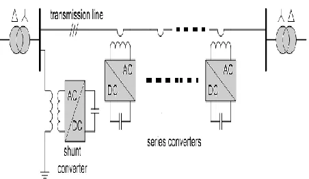
The DPFC is derived from UPFC, which has of one shunt and several single phase series converters which are connected in series with line. The shunt converter acts as a STATCOM whereas the series converter employs the D-FACTS concept, were instead of single three phase converter number of single phase series converters are used. Within the DPFC converters acts independently and they consists of their own capacitors for dc voltage requirement. And here the dc link between the converters is removed and they are connected by transmission line.
Figure 2: distributed power flow controller.
DISTRIBUTE POWER FLOW CONTROLLER AND
DISTRIBUTED INTERLINE POWER FLOW
CONTROLLER
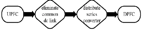
Distributed power flow controller is used for power quality improvement in the system. Distributed power flow controller is achieved by removing link between the converters and by applying D-facts concept to three phase series converter in unified power flow controller .The below flow chart diagram shows how the DPFC is obtained from UPFC
Figure 3: Flowchart from UPFC to DPFC.
IJEDR1602335 International Journal of Engineering Development and Research (www.ijedr.org) 1908 Figure 4: DPFC configuration.
From the figure 4 it can be observed that DPFC consists of one shunt converter, several single phase series converters, high pass filter for controlling the harmonics, and two Y–Δ transformers at both the ends of DPFC.
SERIES CONTROLLER
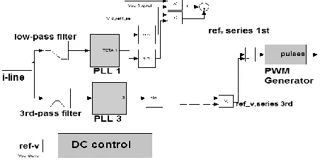
The figure below shows block diagram of series controller which used in DPFC for controlling of single phase series converters.
Figure 5: series controller block diagram.
The single phase series converters which hang to the line via coupled transformer in DPFC consist of independent series controllers. And controller of series converter maintains the dc capacitor voltage of the converter by utilizing the third frequency harmonics and generates the series voltage at fundamental frequency. The inputs of series controller are voltage reference signals from the central controller in dq reference, dc voltage of dc capacitor is another input, and the line current from the line as another input. The block diagram of series controller is shown below. The two voltage reference signals are taken in dq reference and are written in equation form.
t
V
dcos
(1)t
V
qsin
(2)The reference voltage in fundamental component is written as
V
ref1=V
dcos
t
+V
dcos
t
(3)And the principle of vector control method is used for control in the dc voltage which is taken as input from the dc capacitor of series converter. The error signal in dc link capacitor voltage is given by the difference between the reference voltage in dc link capacitor and the actual voltage and the expression is given as,
V
dc,se=V
ref,dc-V
dc (4)The series controller consists of two filters one is the low pass filter which is used to take the current fundamental frequency and another one is the 3rd high pass filter is used to take the current at third harmonic frequency. And these are given to the PLL (phase locked loop) and it is written as equation give below. The reference voltage in third harmonic component is given by,
V
ref3=V
dc,sesin
3
t
(5)And the total voltage in series converter is,
V
ref =V
ref1+V
ref3 (6) And the whole outputs of are given to the PWM generator which generates the current pulse signals for operation of converter.SHUNT CONTROL:
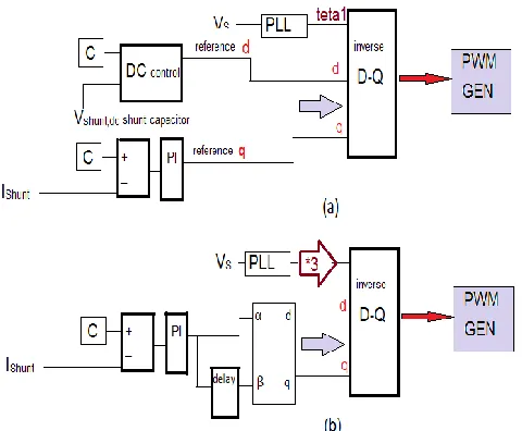
IJEDR1602335 International Journal of Engineering Development and Research (www.ijedr.org) 1909 Figure 6: The shunt control configuration: (a) for
fundamental frequency (b) for third-harmonic frequency.
The shunt converter includes a three-phase converter which is back-to-back connected to a single-phase converter. The three-phase converter absorbs active power from grid at fundamental frequency and controls the dc voltage of capacitor between this converter and single-phase one. .The voltages in dq-reference frame are Vdref and Vqref is taken as
inputs, now, the dqo is transformed into abc by using park’s transformation.
V
a=V
d,refsin
t
+V
q,refcos
t
+V
0 (10)V
b=V
d,refsin(
t
120
)
+V
q,refcos(
t
120
)
+V
0 (11)V
c=V
d,refsin(
t
120
)
+V
q,refcos(
t
120
)
+V
0 (12)By using PWM technique gate pulses are generated for shunt control circuit
Third Harmonic Control: In third harmonic control circuit we have to change the fundamental frequency in to third harmonic frequency so, here we are multiplying with 3 to the frequency.
The voltages in dq0-reference frame is
V
d=V
cos
3
t
+V
sin
t
(7)V
q=V
cos
3
t
-V
sin
t
(8)V
0= 0 (9)Now, the dqo is transformed into abc by using park’s transformation by using the equations (8), (9) and (10). By using PWM technique gate pulses are generated for third harmonic control circuit.
DISTRIBUTED INTERLINE POWER FLOW
CONTROLLER
The Distributed Interline Power Flow Controller (DIPFC) which is FACTS device which is like DPFC consists of many single phase series converters connected to number of transmission lines .The main difference between DPFC and DIPFC is ,in DPFC the series converter had their independent controller and dc capacitor, but coming to DIPFC two series converters of two lines are connected by single dc link capacitor and controlled by single controller, the below figure 7 gives the interior concept used by DIPFC in connecting the two series converter.
Figure 7: IPFC concept.
IJEDR1602335 International Journal of Engineering Development and Research (www.ijedr.org) 1910 MATLAB SIMULATION RESULTS
The simulated system consists of three phase programmable voltage source which is connected to the load using transmission lines of length 180km. By applying three phase ground fault the voltage sags and swells are created in the system. The whole system is simulated in per unit .The parameters used in the system are listed in the table. First the system is simulated without DPFC and there voltages sag and current swells are created .The simulation of the system without DPFC is shown in figure 8.
Figure 8: simulation of two bus system with two parallel transmission lines.
Here is the simulated system with DPFC is shown below in figure 8. Where the voltage sag and current swell is mitigated using DPFC.
Figure 6.2: simulation of two bus system with two parallel transmission lines connected with DPFC.
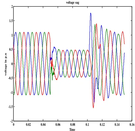
The waveform of voltage sag when DPFC is not connected to the two bus system is shown below in figure 6.3.
Figure 9: voltage sag waveform when the DPFC is not connected to the system.
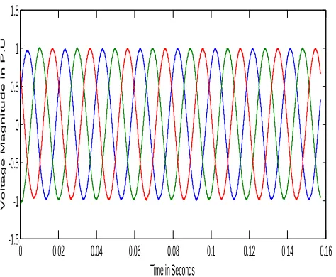
The waveform of voltage sag compensated when DPFC is connected to the two bus system is shown below in figure 10.
Discrete, Ts = 3.255e-006 s.
A B C A B C Three-Phase Fault Vabc Iabc A B C a b c Vabc Iabc A B C a b c A B C a b c A B C a b c N A B C A B C A B C
ABC
100 MW
shunt converter
Discrete, Ts = 3.255e-006 s.
v + -g A B + -g A B C + -A B C A B C Vabc Iabc A B C a b c Vabc Iabc A B C a b c A B C a b c A B C a b c n2 A B C a b c
ABC
abc
Ishunt pulses Conn1 Conn3 Conn5 Conn2 Conn4 Conn6 N A B C A B C A B C i + -pulses 3rd hormonic
ABC
100 MW
0 0.02 0.04 0.06 0.08 0.1 0.12 0.14 0.16
IJEDR1602335 International Journal of Engineering Development and Research (www.ijedr.org) 1911 Figure 10: compensated voltage sag waveform when the
DPFC is connected to the system. The waveform of current swell when DPFC is not connected to the two bus system is shown below in figure 11.
Figure 12: current swell waveform when the DPFC is not connected to the system.
The waveform of current swell compensated when DPFC is connected to the two bus system is shown below in figure 13.
Figure 13: compensated current swell waveform when the DPFC is connected to the system.
And the Total Harmonic Distortion Analysis of the system without DPFC and with DPFC is shown below in figure 6.7 and 14.
Figure 14: Shows the Total Harmonic Distortion Analysis of the system without DPFC.
Figure 15: shows the Total Harmonic Distortion Analysis of the system with DPFC.
0 0.02 0.04 0.06 0.08 0.1 0.12 0.14 0.16
-1.5 -1 -0.5 0 0.5 1 1.5
Time in Seconds
V o l t a g e M a g n i t u d e i n P . U
0 0.02 0.04 0.06 0.08 0.1 0.12 0.14 0.16 -15 -10 -5 0 5 10 15 Time c u r r e n t i n p . u current swell
0 0.02 0.04 0.06 0.08 0.1 0.12 0.14 0.16 -1.5 -1 -0.5 0 0.5 1 1.5
Time in Seconds
C u r r e n t M a g n i t u d e i n P . U
0 0.05 0.1 0.15
-1 0 1
Selected signal: 8 cycles. FFT window (in red): 6 cycles
Time (s)
0 2 4 6 8 10
0 10 20 30 40 Harmonic order
Fundamental (50Hz) = 0.752 , THD= 16.08%
M ag (% o f F un da m en ta l)
0 0.05 0.1 0.15
-0.5 0 0.5
Selected signal: 8 cycles. FFT window (in red): 4 cycles
Time (s)
0 2 4 6 8 10
0 0.1 0.2 0.3 0.4 0.5 0.6 Harmonic order
Fundamental (50Hz) = 0.9516 , THD= 0.71%
IJEDR1602335 International Journal of Engineering Development and Research (www.ijedr.org) 1912 Here Distributed Interline Power Flow Controller is kept in
the same two bus system where DPFC is placed and it is shown below in figure 6.9.
Figure 16: simulation of two bus system with two parallel transmission lines connected with DIPFC.
Total Harmonic Distortion Analysis of DIPFC is show in figure 6.10
Figure 17: total harmonic distortion analysis of the system with DIPFC.
The Total Harmonic Analysis of DPFC and DIPFC are compared below and Total Harmonic Distortion Analysis
values are placed in a table. The table consists of Total Harmonic Distortion Analysis values of system Without DPFC, with DPFC, with DIPFC.
CONCLUSION
In this case study both DPFC and DIPFC are connected in the system with three phase source connected to the load with two parallel transmission lines, it is designed with the help of MATLAB. The voltage sag and current swell in the system is a caused by using a three-phase fault close to the load. The faults occurred in the system were compensated by using facts device DPFC and DIPFC results were obtained and their results were compared. When comparing DPFC with DIPFC, DIPFC has more effectively improved the power quality of the system and it mitigated the voltage sag and current swell in the system and it can be observed from the THD analysis of the both DPFC and DIPFC.
REFERENCES
1. Zhihui Yuan, Sjoerd W.H de Haan, Braham Frreira and Dalibor Cevoric “A FACTS Device: Distributed Power Flow Controller (DPFC)” IEEE Transaction on Power Electronics, vol.25, no.10, October 2010
2. S. Masoud Barakati, Arash Khoshkbar Sadigh and Ehsan Mokhtarpour, “Voltage Sag and Swell Compensation with DVR Based on Asymmetrical Cascade Multicell Converter”, North American Power Symposium (NAPS), pp.1 – 7, 2011
3. Alexander Eigels Emanuel, John A. McNeill “Electric Power Quality”. Annu. Rev. Energy Environ 1997, pp. 263-303. 4. I Nita R. Patne, Krishna L. Thakre “Factor Affecting Characteristics of Voltage Sag Due to Fault in the Power System” Serbian Journal of Electrical engineering. vol. 5, no.1, May2008, pp. 171-182.
5. Zhihui Yuan, Sjoerd W.H de Haan and Braham Frreira “DPFC control during shunt converter failure” IEEE Transaction on Power Electronics 2009.
6. J. R. Enslin, “Unified approach to power quality mitigation,” in Proc.IEEE Int. Symp. Industrial Electronics (ISIE ’98), vol. 1, 1998, pp. 8–20.
7. B. Singh, K. Al-Haddad, and A. Chandra, “A review of active filters for power quality improvement,” IEEE Trans. Ind. Electron. vol. 46, no. 5, pp. 960–971, 1999.
8. M. A. Hannan and Azah Mohamed, member IEEE, “ PSCAD/EMTDC Simulation of Unified Series-Shunt Compensator for Power Quality Improvement”, IEEE Transactions on Power Delivery, vol. 20, no. 2, April 2005. 9. P. Pohjanheimo and E. Lakervi, “Steady state modeling of custom power components in power distribution networks,” in Proc. IEEE Power Engineering Society Winter Meeting, vol. 4, Jan. 2000, pp. 2949–2954.
shunt converter Discrete, Ts = 3.255e-006 s.
v + -g A B + -g A B C + -A B C A B C A B C a b c Vabc Iabc A B C a b c Vabc Iabc A B C a b c A B C a b c A B C a b c n2 A B C a b c
AB C ab c
Ishunt pulses Conn11 Conn21 Conn1 Conn3 Conn5 Conn7 Conn12 Conn22 Conn2 Conn4 Conn6 Conn8 N A B C A B C A B C i + -pulses 3rd hormonic
ABC
100 MW
0 0.05 0.1 0.15
-0.5 0 0.5
Selected signal: 8 cycles. FFT window (in red): 4 cycles
Time (s)
0 2 4 6 8 10
0 0.1 0.2 0.3 0.4 Harmonic order
Fundamental (50Hz) = 0.9756 , THD= 0.45%
IJEDR1602335 International Journal of Engineering Development and Research (www.ijedr.org) 1913
10. A. L. Olimpo and E. Acha, “Modeling and analysis of custom power systems by PSCAD/EMTDC,” IEEE Trans. Power Delivery, vol. 17, no.1, pp. 266–272, Jan. 2002.
11. R. Zhang, M. Cardinal, P. Szczesny and M. Dame. “A grid simulator with control of single-phase power converters in D.Q rotating frame”, Power Electronics Specialists Conference, IEEE 2002.
First Author: T. Vijaya
Lakshmi Bhavani is pursuing her M.Tech from Sri Vahini Institute of Science and Technology, Tiruvuru, Krishna dt. Her Research Interests is Power Systems.
Second Author: N. Nageswara Rao