Review
Recent Progress in the Performance Enhancement
of Phase-Sensitive OTDR Vibration Sensing
System
Romain Zinsou1, Xin Liu1, Yu Wang1, Jianguo Zhang1, Yuncai Wang1,2 and Baoquan Jin1,3*
1 Key laboratory of advanced transducers and intelligent control systems (Ministry of education and Shanxi province), Taiyuan University of Technology, Taiyuan 030024,China; [email protected]; [email protected]; [email protected]; [email protected];[email protected]
2 College of Physics and Optoelectronics, Taiyuan University of Technology 3 State Key Laboratory of Coal and CBM Co-mining, Jincheng 048000, China Corresponding author: [email protected]; Tel: +86-138-3515-5702
Abstract: Recently, the phase-sensitive OTDR (Φ-OTDR) based vibration sensor system has gained the focus of many researchers and some efforts have been undertaken to push further the limitations imposed on the performance of the Φ-OTDR sensor system. Then, progress in the different areas of its performance evaluation factors such as: improvement of the signal-to-noise ratio (SNR), spatial resolution (SR) in the sub-meter range, enlargement of the sensing range, frequency response bandwidth over the conventional limit and phase signal demodulation for quantitative measurement have been realized. This paper presents an overview of the recent progress in the Φ-OTDR based vibration sensing system in the different areas mentioned above.
Keywords: Optical fiber-sensors; Rayleigh backscattering; Φ-OTDR system; Vibration measurement.
1. Introduction
Owing to their insensitivity to electromagnetic interference, corrosion resistance, electrical insulation, intrinsic safety, good concealment, low cost…, the optical fiber sensors have demonstrated their superiority over the other existing types of sensors [1, 2]. The optical fiber sensors as their name implies, use the optical fiber as the sensing medium. They can be used for static strain, temperature, pressure and dynamic vibration measurement [3-5]. Among the optical fiber sensors, the Φ-OTDR sensor system has attracted much more interest for use as dynamic vibration sensor because of its high sensitivity, large dynamic range, full distribution, simple configuration and relatively easy processing scheme. These types of sensors can find their applications in the fields of security such as: monitoring the pipelines, the national borders, military bases, state buildings, prisons, embassies, seismic wave detection, etc. Although the Φ-OTDR based vibration sensor system has demonstrated its supremacy over the other types of optical fiber sensors, it has not always been the case. Previously the Φ-OTDR sensor system was limited by a low signal to noise ratio (SNR), reduced dynamic range (DR), spatial
resolution (SR) in the range of tens of meter, the tradeoff between the frequency response bandwidth and sensing range, the nonlinear relationship between the detected vibration and the optical intensity signal causing obstacle to use the Φ-OTDR system for quantitative vibration measurement [6-8]. In order to enhance its system performance, many research works have carried out some techniques and signal processing methods to push further the limitations imposed on the Φ-OTDR system by such factors.
In this paper, we present an overview of the recent progress in the Φ-OTDR based vibration sensor system in response to the limiting factors mentioned above. The remainder of this paper is structured as follows: firstly we describe the basics operating principle of the Φ-OTDR system, in section 3, we discuss about the methods and techniques for improvement of the SNR, section 4 is dedicated to the Φ-OTDRsystem configurations for very large sensing range, the proposed techniques for improvement of the SR and for extension of the frequency response bandwidth of the system are reported in section 5 and 6. The next section addresses the Φ-OTDR system for quantitative measurement, our conclusion is summarized in the last section.
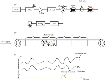
Figure 1. (a) Setup of a Φ-OTDR system, (b) illustration of Rayleigh phenomenon, (c) intrusion detection. NLL: narrow line-width laser, OM: optical modulator, EDFA: erbium-doped fiber amplifier, DAQ: data acquisition card, PD: photo-detector, PC: personal computer.
2. Basics operating principle of the Φ-OTDR system
amplify the optical power, then the amplified spontaneous emission (ASE) noise is filtered out before being sent into the fiber under test (FUT) through a circulator. The Rayleigh backscattered light is detected by a PD and processed later by a personal computer (PC).
Figure 1b is an illustration of the Rayleigh backscattering phenomenon. In fact, the inhomogeneities (illustrated as black spot inside a pulse-width) in the refractive index of the optical fiber due to the imperfect manufacture constitute the scattering centers that act together to produce the Rayleigh backscattered signal detected by the PD. Because of the huge number of the scatterers, the detected signal exhibits a slowly varying speckle-like waveform until an intrusion to the system brings out an apparent change to the detected signal. Then, the detected signal intensity differential method can be used to detect the intruder location (see figure 1c).
Several parameters are designed to appreciate the performance of a Φ-OTDR sensor system such as the SNR, the SR, the DR, the frequency response bandwidth, the capability for performing quantitative measurement etc. The first three parameters are extremely related to each other. The SR of a measurement is the minimum distance between two intrusions locations allowing them to be clearly non-overlapped. The SNR and the DR vary in the same direction, an increase of the SNR implies an increase of the DR. When considering the discrete model for representation of the Rayleigh backscattering and assuming a rectangular short pulse with a pulse-width of Tp as input light to the FUT, the detected backscattered signal is formed by the convolution of the probe light with the backscatter impulse response so that the SR and the detected optical power P can be written as [11]:
{ SR=
vgTp
2 P=1
2αvgSP0Tpexp(-αvgt),
(1)
where is the attenuation coefficient of the fiber, vgis the group velocity of the probe pulse, S is the backward capture coefficient and P0 is the input optical power coupled into the FUT. The early methods proposed to improve the SNR of the Φ-OTDR system is to increase the energy coupled into the FUT through the optical pulse by increasing the input optical pulse’s peak power or its pulse-width. Unfortunately, the maximum optical power of the input light is limited by the nonlinear effects described in [12, 13]. When reaching the maximum tolerable optical input power, the only one way to increase the SNR of the system is to enlarge the pulse-width of the input signal to the FUT. This operation sacrifices the SR of the system. Then, a tradeoff between the SNR and the SR shows up as a limiting factor for the DR of the measurement of the Φ-OTDR system [12].
For a distributed measurement with a Φ-OTDR system and a FUT of length L, the pulse period (PP) of the input optical power is designed such that its value is greater than or equal to the round-trip time of the light in order to prevent the pulse overlapping:
PP≥2L
vg. (2)
fmax= 1 2PP≤
1 2(
vg
2L), (3)
while the minimum detectable vibration frequency is determined by the noise present in the system.
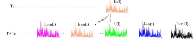
Figure 2. Principle of the active compensation of the laser output frequency drift N and f are respectively the sweep number and the frequency sweep step, n is the number corresponding
to the OTDR trace best correlated to the previous.
3. Methods and techniques for improvement of the SNR in Φ-OTDR sensor system
frequency sweep step f. Figure 2 describes the working principle of the method: At an instant of time t0, the laser output frequency is f0 and an initial Φ-OTDR trace is recorded; at any other instant of time, because of the laser frequency drift the laser output frequency is f different from f0. When sweeping the laser output frequency from f-Nf to f+Nf, 2N+1 traces are recorded and the best correlated to the previous trace is found out in such a way that the two highly correlated traces can be considered as arising from the same laser frequency output. Doing this continuously enabled them to suppress the influence of the laser frequency drift and make it possible to locate a vibration with frequency as low as 0.5Hz. The veritable problem with this method is the relatively long time needed for data transmission and processing which reduced significantly the dynamic performance of the system.
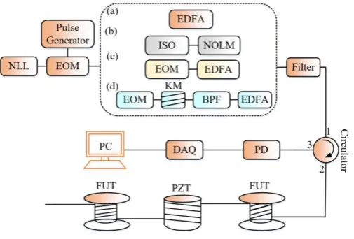
Figure 3. Experimental setup for comparison of the Φ-OTDR system basing on the ER: (a) conventional scheme; and higher ER schemes with: (b) NOLM: non-linear optical loop mirror
(c) two-cascaded EOMs and (d) the nonlinear Kerr effect respectively. ISO: optical isolator, KM: Kerr medium, the other acronyms are defined previously.
Another important source of noise in Φ-OTDRsystem, which needs to be controlled, is the finite extinction ratio (ER) of the optical modulator. During the process of conversion of the continuous light from the laser into optical pulses, there is always a part of the continuous leakage light that cannot be suppressed and the received signal is made of the pulse and the continuous backscattered light parts respectively. The leakage light part of the Rayleigh backscattering signal acts as a noise that affects the sensitivity of the Φ-OTDR system [18-20]. TheSNRof the system is linked to the ER of the optical modulator as [18]:
𝑆NR(z) = √ER√sinh( vgTpα
2 )exp(-2αz)
2(1-exp(-2αL)) , (4)
pulses are respectively the nonlinear optical loop mirror (NOLM), the association of two electro-optic modulator (EOM), and the nonlinear Kerr effects on the sinusoidally modulated optical signals (SMOS) methods. The experimental results indicate in the case (b) that, when the pulse is off and only the continuous leakage light is coupled into the FUT, the noise floor in the system with NOLM (ER=60dB) is 11dB lower than the system with conventional one (ER=30dB). In (d), the principle of generation of high ER optical pulses is based on the fact that a SMOS passing through a nonlinear Kerr medium experiences the self-phase modulation and generates at its output some new spectral components such that any small change in ER of the pulses at the input of the Kerr medium can cause large variation in the ER of the different components at the output of the Kerr medium expressed as:
ɛout(n)
[dB]=(2n+1)ɛin[dB]-3.2n-2.7; 5dB< ɛin<40dB, (5)
where ɛin is the ER of the pulse signal input to Kerr medium, ɛout (n)
is the ER of the nth order sideband component of the output, n being an integer ranging from 1 to 6. In (d), the two cascaded EOMs are driven respectively by sinusoidal and square pulse electrical signal to form an impressed square-pulse SMOS, then the Kerr medium causing the self-phase modulation phenomenon to produce the sidebands that are sent later to a BP optical filter to select the desired component with higher ER. The method has been regularly implemented in Φ-OTDR system and its influence on the system performance has been effectively demonstrated.
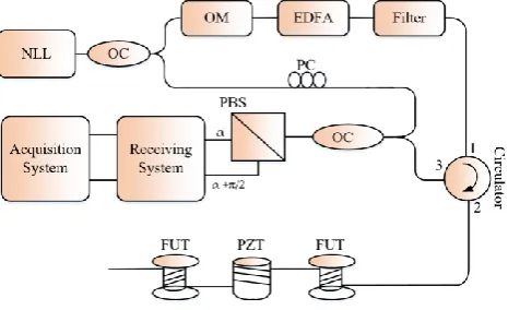
Figure 4. Schematic of the polarization diversity technique in Φ-OTDR system. OC: optical coupler PC: polarization controller.
case of direct detection [22], is much more serious in the coherent detection-based system since there is polarization mismatch between the Rayleigh backscattered signal and the reference light signal. Consequently, the polarization maintaining fibers configurations systems shouldn’t be subject to that phenomenon [23]. In work [24], the authors adopted the polarization diversity technique to overcome the polarization induced fading problem in a coherent Φ-OTDR system (figure 4). For that purpose, a polarization beam splitter is used to divide the detected signal into orthogonal polarization states components and processed differently. The experimental results demonstrate for each of the processed signal an improvement of the SNR of respectively 10.9dB and 8.95dB.
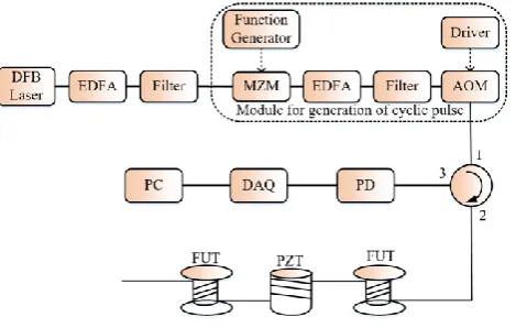
Figure 5. Experimental setup of the proposed pulse coding in Φ-OTDR system. MZM: Mach-Zehnder modulator.
Recently, Y. Muanenda et al. proposed the introduction of the cyclic pulse coding in Φ-OTDR system, which method enables to send higher quantity of energy in the system while avoiding the nonlinear effects so that the SNR of the system can be improved[25]. The basic idea subtending the pulse coding is that measuring several objects together instead of separately may make it possible to determine more accurately than the individual measures. The key of the coding technique in [25] is the S-code. The procedure consists of two steps: the pulse encoding and pulse decoding. During the pulse encoding, the authors injected into the FUT a sequence S-coded rectangular pulses while avoiding interference from two consecutives pulses such that the resulting backscattering for any position in the FUT is the integration from that of many pulses. The pulse-decoding step is to obtain the equivalent single-pulse backscattering trace by multiplication of S-1 and the vector of the backscattering trace from many pulses. So, the improvement in SNR compared to the single-pulse can be evaluated. The implementation of cyclic pulse coding in Φ-OTDR system (figure 5) required the laser light to be coherent within a pulse-width and incoherent outside to assure the linearity of the optical intensities addition. These conditions associated together with the expression of the laser coherence length for a Lorentzian shape imposed on laser light line-width to satisfy:
Nmax π×RTT
≤ ≤ 1 π×Tp
, (6)
In the experiment, a pair (MZM, AOM) assured the production of cyclic pulses, first the MZM is used to produce continuous pulses in ‘1’ state and later the AOM to generate a high ER light signal at his output. The advantages of the proposed system include low-cost compared to the conventional Φ-OTDR using a highly coherent laser source and offering, an improvement in the SNR of nearly 9dB without affecting the frequency response bandwidth of the measurement.
L. Y. Shao et al. suggested an adaptive 2D bilateral filtering algorithm in aΦ-OTDR system to enhance the SNR [26]. The proposed bilateral filtering algorithm uses the weighted average with the geometric weight reduced to a simple Lorentz function so that tuning the gray level standard deviation alone can be sufficient to remove the noise in the system without altering the desired signal. The proposed method is implemented in coherent detection scheme, an improvement of ~14dB of the SNR with a sensing range of 27.6km has been experimentally demonstrated without deterioration of the SR. For faster signal processing, the filtering window size was set to 20 and the double iteration was preferred since there is no consequent SNR improvement for greater filtering window size, while higher filtering window size consumes the processing time. Better SNR improvement with the default of relatively long signal processing time has been proposed before based on empirical mode decomposition (EMD) method in work [27]. In this method, the raw Rayleigh backscattered signals were first decomposed into intrinsic mode functions (IMF) and a residual component through the sifting algorithm. Later, the Pearson correlation coefficient between the signal and the IMF is found out so that the high frequency noise component will be progressively eliminated through filtering. The method demonstrated a SNR of more than 40dB in a sensing range of 2km to detect respectively 100 Hz and 1.2 kHz vibrations. Many others signal processing-based methods to enhance the SNR in Φ-OTDR system have been also such as wavelet de-noising method [28], 2D edge detection [29] etc.
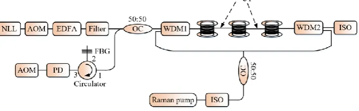
Figure 6. Experimental system of a Φ-OTDR system assisted with Raman amplification. WDM: wavelength division multiplexing, FBG: fiber Bragg grating filter.
4. Configurations ofΦ-OTDRsystem for large sensing range
An important parameter limiting previously the practicability of the Φ-OTDR system is its reduced DR. For a given SR, increasing the optical peak power input to the FUT via an EDFA causes an increase of the DR and the SNR of the system while the input optical peak power cannot be indefinitely increased due to the nonlinear effects. Consequently, this method cannot improve significantly the DR of the system. Most of the Φ-OTDR sensor systems rely on the optical amplification for consequent extension of the DR.
amplification technology to extend the sensing range in a Φ-OTDR system to 62km with a SR=100m [30]. The proposed experimental setup is shown in figure 6. For their experiment, the authors adopted the bi-directional Raman amplification with a gain equalization offering even distribution along the sensing fiber than any other scheme. The bi-directional Raman pump power evolution is governed by the equations [31]:
{
dPP
dz =gRPRPP-αPPP
γdPR dz
=-ωR
ωSgRPRPP-αR
, (7)
where Pp, PR are respectively the pulse and pump power; αR , αP are respectively the transmission losses of the pump and the signal, ωR, ωS are respectively the frequencies of the
pump and signal light respectively, gR is the Raman gain and =+1(-1) depending on the
pumping direction.
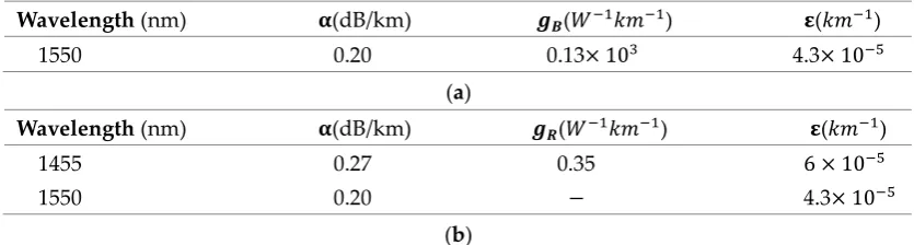
Later, the authors implemented the method in a coherent detection based Φ-OTDR system. In this scheme, the heterodyne detection removes the ASE noise caused by the high power of the Raman pump and a wise choice of the probe pulse power and the Raman pump power enables them to avoid the SBS and realize a 131.5km long sensing range and 8m SR in the Φ-OTDR system [32]. Furthermore, the same research group utilized a hybrid amplification scheme made simultaneously of co-pumping second-order Raman amplification, counter-pumping first-order Raman amplification and counter-counter-pumping Brillouin amplification with the caution that each pumping scheme controls a certain region of the FUT [33]. Table 1 provides the working conditions of the different pumping schemes. With this method the sensing distance is enlarged to 175km with a SR of 25m and a SNR=12dB, the experiment was carried out with a highly coherent laser whose line-width is 100Hz. The laser output light is split twice by two optical couplers to create the reference light and two inputs probe light for both ends of the sensing fiber, a microwave generator driving an EOM maintains the frequency gap between the input light and the Brillouin pump while light depolarization helped to suppress the polarization gain dependent influence. Experimental results demonstrate the necessity of complicity between the different pumping schemes to keep the signal power high enough along the whole sensing distance.
Table 1. Working conditions of the pump schemes: (a) for the Brillouin amplification, (b)
for the Raman amplification.
Wavelength (nm) 𝛂(dB/km) 𝒈𝑩(𝑊−1𝑘𝑚−1) 𝛆(𝑘𝑚−1)
1550 0.20 0.13× 10³ 4.3× 10⁻⁵
(a)
Wavelength (nm) 𝛂(dB/km) 𝒈𝑹(𝑊−1𝑘𝑚−1) 𝛆(𝑘𝑚−1)
1455 0.27 0.35 6 × 10⁻⁵
1550 0.20 − 4.3× 10⁻⁵
(b)
of the system and in this sense a Φ-OTDR sensor system in its original structure with relatively long sensing distance will be more desirable. F. Pang et al. used the standard deviation of the amplitude of the demodulated signal in a coherent detection based Φ-OTDR system with high speed data acquisition card (12-bit, 1GS/s) to detect the intrusion in a 50km long FUT with a SNR of nearly 32dB [35].
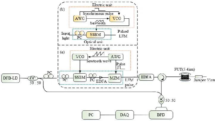
Figure 7. Experimental setup of the pulse-compression Φ-OTDR with (a) the primitive scheme for generation of the LFM pulse, (b) the improved scheme. SSBM: single sideband modulator,
VCO: voltage-controlled oscillator, AWG: arbitrary waveform generator.
5. Φ-OTDRsystem with spatial resolution in the sub-meter range
by a square pulse synchronized with the VCO to produce the pulsed LFM signal. The authors demonstrated experimentally a SR of 47cm in a sensing range of 5.4km with the method. Later, a system gaining in stability has been proposed by the same research to group to improve the SR to 10cm with the same sensing range [37]. The new method for the generation of the pulsed LFM signal (see module (b)) suppresses the need of a MZM and used only the VCO under the simultaneous action of a sawtooth and a rectangular signal originating from an AWG to drive the SSBM. In this case, the pulsed LFM has better ER that impacts on the system performance as described in section 3. In work [38], H. Cai et al. proposed the Φ-OTDR system with frequency swept-pulse based on the same principle as described previously. Here, the LFM signal after production is sent into a DFB-LD by injection locking to enhance the ER and the sweeping range of the LFM signal which is transferred later to an AOM synchronized with the VCO to generate the pulsed LFM signal. Once generated, the pulsed LFM signal is amplified and launched into the FUT. With this scheme the LFM pulse frequency bandwidth was extended to 420MHz and aΦ-OTDRsystem with a SR of 30cm and a sensing range as long as 19.8km has been realized for the first time.
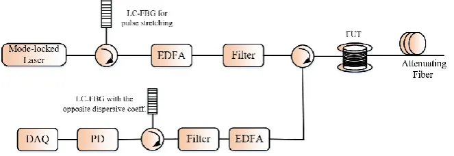
Figure 8. Setup of the chirped pulse Φ-OTDR system. LC-FBG: linearly chirped fiber Bragg grating.
Basing their analysis on the fact that the noise sources such as the random nature of laser phase, the light SoP mismatch, the I/Q quadrature imbalances may affect the numerical compression in the OPCR, J. Pastor-Graells et al. proposed a Φ-OTDR system using the chirp pulse amplification to realize the optical domain pulse-compression [39]. The proposed chirp pulse amplification Φ-OTDR system is the conventional Φ-OTDR system including two linearly chirped fiber Bragg gratings (LC-FBGs) with opposite dispersion coefficient. The first LC-FBG stretches an ultra-pulse in the range of picosecond which is launched into the FUT after amplification and the Rayleigh backscattered signal is compressed with the second LC-FBG (see figure 8). In fact, in the conventional Φ-OTDR system, the backscattered signal trace is expressed in both the time and frequency domains as [39]:
{ I(t)~p(t)*f(t)
I(w)=P(w)×F(w), (8)
{
I'(w)=G×P(w)×F(w)×𝑒𝑥𝑝[+j(Ф̈
2)w 2]
⏟
pulse stretching
× exp[-j(Ф̈
2)w 2],
⏟
trace compression
I'(t)=G×I(t),
(9)
I’ is the signal intensity in the proposed system, Ф̈ is the second-order dispersive coefficient of the LC-FBG and G the amplification gain factor. The SNR of the backscattering trace is improved according to the amplification gain factor G while the SR is kept same as before pulse stretching. A SR of 1.8cm in sensing range of 8m limited by the high repetition rate of the locked laser to generate the coherent narrow pulses with an increase of ~20dB in the SNR compared to the conventional Φ-OTDR system. The demonstrated temporal width was wider than the pulse-width because the 35GHz bandwidth of the PD used in the experience is lower than the pulse bandwidth. Later, the authors improved the SR of the system to 3mm by replacing the PD with that of 45GHz bandwidth [40].
Figure 9. Signal processing for vibration measurement in FDM Φ-OTDR system.
6. Φ-OTDR system with frequency response bandwidth higher than the limit set by the sensing range
give respectively the location and the frequency of the external vibration applied to the PZT. For their experiment, the technique was implemented in a coherent detection-based system. To produce the probe pulse sequence light, an EOM driven by an electrical signal with its frequency changing in a staircase pattern generates at its output a multi-frequency signal which is in turn pulse-modulated by an AOM. The effectiveness of the FDM Φ-OTDR was firstly demonstrated to detect a 3.4kHz square wave located at 9.5km of the FUT with four frequency components (n=4). The multiple backscattered signals corresponding to different frequency components is acquired with a DAQ at a sampling rate of 500MHz/S, then the phase demodulation is performed to restore the external applied vibration. The FFT results of the reconstructed vibration confirmed the presence of the applied vibration frequency and its harmonics up to 20kHz, what is not detectable with the conventional single-frequency pulse Φ-OTDR since the repetition rate limit should be 5kHz in a FUT of 10km length. With this method, the number n of frequency components in the probe pulse sequence can be changed depending on the DAQ rate and the capacity of the computer used for data processing.
A FDM Φ-OTDR system performing better than the one described previously has been suggested by D. Iida et al. [44]. For their experiment, the authors used a 1.25GHz/S DAQ as the signal receiver and the pulse sequence was made of n=16 frequency components with the caution to prevent the SBS. To measure the vibration, the short-time Fourier transform is applied to the multiple back-scattered detected signals to obtain n OTDR traces. After the propagation of a certain number k of pulse sequences into the FUT, the n×k OTDR traces denoted as Aij(t) (1≤i≤n, and 1≤j≤k ) are arranged chronologically in the time-domain and a FFTis applied to the data for the different positions to extract the vibration information. Figure 9 is an illustration of the signal processing procedure. In this experiment, the authors successfully extracted an 80kHz vibration along a FUT of5km, which is over the limit set by the repetition rate in a conventional Φ-OTDR.
Figure 10: Experimental setup for the implementation of the FDM in direct-detection Φ-OTDR system. wL and wH are the frequency shifts introduced by the AOM in the dual-pulse pairs.
is the pulse-width, ts is the double pulse spacing time. IM is an intensity modulator and APD
is an avalanche photo-detector.
the measurement range [45]. The method works by using a frequency step sweeping laser source and modulating the AOM such a way to generate a dual-pulse pairs with different frequency-shifts. A low-bandwidth avalanche photo-detector (APD) should eliminate the interference signal between the dual-pulse pairs and the use of the phase extraction method will allow to recover the external vibration. Figure 10 shows the illustration of the setup for the FDM dual-pulse Φ-OTDR. In their experiment, a NLL combined with an intensity modulator designed to introduce an appropriate frequency offset acts as a tunable laser source and the AOM to generate a sequence of four raised-cosine shaped pulse-pairs with different frequency spacing to probe the FUT. It’s worth to mention that the pulse shape here is changed from the conventional rectangular-shaped pulse in order to remove the influence of the crosstalk due to the double-frequency probe signal on the detection. The detected signal by the low-bandwidth APD has been passed through four digital BPF whose center frequency correspond respectively to the spacing frequency and the beat signal corresponding to the four intensity signals are used for the phase extraction. The method demonstrates with success the recovery of an external vibration with its frequency ranging from 1 to 17kHz with a flat response for a sensing range of 10km. It should be noted that the maximum detectable frequency for the conventional direct-detection Φ-OTDR system for such sensing range should be 5kHz according to the relation (3).
Figure 11. A concept of dynamic strain detection in Φ-OTDR based sensor.
7. Φ-OTDR system for recovery of the full vector information of the external vibration
analysis of a large amount of data and the demodulation result was also very sensitive to the coherent Rayleigh noise. To eliminate the Rayleigh fading, Masoudi et al. introduced a MZI associated with a 3×3 symmetric coupler at the output at the receiving end of the Φ-OTDR system and the polarization diversity technique has been used to recover the phase change induced by the disturbance [47]. The concept of the phase shift induction in the detected optical intensity signal is illustrated in figure 11. The technique has demonstrated experimentally a phase demodulation with a frequency response bandwidth of [500-5000Hz] and respectively a SR of 2m and strain resolution of 80n. The main problem here is that the system’s stability is determined by the MZI which is very sensitive to the ambient temperature variation and also, there is a need of three sensitive PDs working synchronously at the receiving end of the system.
Figure 12. Pulse pair sequences with a phase shift of 0, +2/3, -2/3 respectively in the second pulse.
Later, Alekseev et al. proposed a scheme maintaining the simple configuration of the Φ-OTDR system using the dual pulsed phase modulated light to probe the FUT and the phase diversity technique to rebuild the applied vibration [48]. The principle of the technique is to generate cyclically three groups of pulse pairs in such a way the second pulse of each sequence is respectively 0, +2/3, -2/3 phase shifted by a phase modulator (see figure 12), so that three groups of Rayleigh backscattered signals phase shifted in the same order with the pulse pair sequences are detected and processed according to the phase diversity technique. The technique was consistent to recover different kinds of vibration. The drawback of this technique is that the system’s frequency response bandwidth is reduced by 1/3. In work [49], Z. Wang et al. thought of the I/Q demodulation technique in a coherent based Φ-OTDR to reconstruct the external vibration applied to the FUT; an acoustic frequency-shifter is placed in the local light branch to compensate the phase shift introduced in the signal branch by an AOM so that the system is a homodyne detection. Then, the local light and the Rayleigh backscattered signal are input to a 90optical hybrid which generates at its output two quadrature componentsI(t) and Q(t). The I/Q components are processed to recover the induced phase shift(t) according to the I/Q demodulation algorithm. Figure 13 is the experimental setup of the system.
Y. K. Dong et al. also used the I/Qdemodulation technique in the coherent detection system [50]. The system here is the heterodyne detection. The two-quadrature components I(t) and Q(t) are related to the phase of the backscattered signal and the strain by:
{
φ(t)= arctan(I(t)
Q(t))+mπ,
∆φij
zij∆ϵ= 4π
λ (n+Cϵ),
(10)
strain parameter and is the laser output wavelength. The conditions of the experiments were very strict (at night on the first floor to avoid the environmental disturbance) and close attention was paid to the induced noise through the use of the polarization-maintaining fiber and polarization beam splitter. With this method the authors demonstrated experimentally a precise dynamic strain measurement in the range 10-1000n with a strain resolution of 1 or 2n according to the SR of 2.5m or 5m.
Figure 13. Setup of the Φ-OTDR based sensor for nano-strain measurement. AFS: acoustic frequency shifter.
Early methods used for precise quantitative measurement of temperature/strain in Φ-OTDR system were based on the compensation of the refractive index change induced n by a frequency shift of the pulse launched into the FUT. This method progressed from static temperature/strain measurement to dynamic measurement. In work [51], Koyamada et al. considered the Rayleigh backscattered light as the interference of two signals, one is sensitive to the temperature/strain while the second is not. To measure the temperature/strain, the FUT is divided into many sections subjected to two different controlled temperatures Ta and Tb and the Rayleigh backscattered signals Pa(, z) and Pb(, z) were performed and compared through their cross-correlation value. When the two values of temperature are equivalent, the signals Pa(, z) and Pb(, z) are highly correlated, by contrast when Ta is different from Tb then Pa(, z) is highly correlated to Pb(+, z) where is the frequency shift that compensates the variation in temperature and strain as expressed in the relations (11):
{
∆ʋ
ʋ0=-0.78×∆ϵ ,
∆ʋ
ʋ0=-(6.92×10
-6)×ΔT, (11)
Pastor-Graells et al. showed an improvement in the technique by using a linear chirped pulse instead of the single-frequency pulse in the conventional Φ-OTDR system in the direct detection scheme [53]. During the pulse propagation, the frequencies components of the pulse vary with the position in the FUT, so that any refractive index change n induced by any disturbance will shift longitudinally the same Φ-OTDR trace pattern by z in such that the frequency shift compensator of the change n (respectively the temperature/strain) can be deducted from z. This method avoids the time-consuming frequency sweep operation and then impacts on the dynamic nature of the measurement. The longitudinal shift z is found out through the cross-correlation of two consecutives detected signals and continuously to extend progressively the sensing range. The linear chirped pulse has been experimentally realized by driving the laser source with a repetitive ramp electric signal. With this technique, the measurement is relative and the measurement range can be extended progressively, experimental demonstrations showed 1mK/4n resolution with a SNR>25dB. The limitation with this method is that the detectable n from trace to trace should be in a certain precise range to avoid cumulative errors and the high digitization speed needed to cover the total bandwidth of the chirp signal used. Later works of the same research group investigate the impact of the laser line-width on the accuracy of the temperature/strain measurement [54, 55]. The experimental results demonstrate that the narrower the line-width of the laser is the more accurate the measurement is and proposed to subtract the longitudinal shift of the sensing region from the longitudinal shift caused in the unperturbed region in order to remove the impact of the laser frequency drift on the measurement accuracy. Another work, studies the extension of the sensing range with the assistance of the Raman amplification [56]. The linear chirped pulses -OTDR system brings some new features that deserve close attention for studies.
By contrast, H. Feng and al. suggested the phase demodulation method in Φ-OTDR without coherent detection utilizing both single and dual-pulse probe schemes [57]. To do so, the authors modeled the cosine-relationship of the backscattered signal in the disturbance region as:
Ii(t)=Di+Ai.cos(θ(t)+Ψi), (12)
where Di, Ai and i are slowly varying quantities,(t) represents the phase to be recovered. The phase demodulation here, is conducted as follows: firstly, normalize the detected intensity at two adjacent points in the disturbance region, process the sum and the difference of the normalized version of these intensities and then a second normalization to generate the I/Q quadrature components. Finally, the phase signal (t)can be recovered as requires the I/Q demodulation. The authors have tested successfully this method with three different kinds of vibrations: single-frequency vibration, amplitude-modulated vibration and chirped vibration. The main problem with this method is the influence of the coherent Rayleigh fading which generates some undesirable spikes in the demodulated phase signal.
detected light is an interference of the lights recombined by the optical coupler with a time delay since there is a difference in the optical path length and expressed as:
Ii(t)=ID+IC.cos(C.cos(wc.t+(t)), (13)
where ID and IC are respectively the dc current and the amplitude of the ac current, C and wc are respectively the carrier modulation depth and frequency, (t) the phase to be recovered and later the phase demodulation is performed according to the PGC-Atan algorithm. The experiment demonstrated a system with a SR of 6m, a sensing range of 10km and a SNR of 30.45dB. This method is insensitive to light intensity disturbance since the demodulated result is independent of ID and IC. Two limitations can be noted for this approach: 1- the MI at the receiving end of the system is temperature sensitive, 2-The demodulation technique implemented imposes on the carrier modulation depth the value C=2.63 so that J1(C)=J2(C) while keeping the modulation depth strictly constant is still a challenge. In work [59], the authors developed a concept similar to the one described previously but the technique utilized for production of the carrier signal and the phase demodulation technique are different. To generate the carrier signal, the continuous light from the laser converted into pulse light through an optical modulator is split into two via an optical coupler to obtain a pulse pair. An electro-optic phase modulator placed in one of the branches modulates one of the pulse pair and another optical coupler recombines the two pulse signals before being sent into the FUT. The interference signal from the two pulses and detected by the PD is effectively sinuoisaidally phase modulated. Experimental results demonstrate a positive influence caused by the phase modulation on the Rayleigh back-scattered signal. The demodulation algorithm utilized here does not need to apply the phase unwrapping algorithm like in the PGC-Atan, which algorithm is computationally intensive especially in interferometry system and by the way avoids also the eventual demodulation errors due to wrong unwrapping caused the fluctuation of the carrier amplitude.
Figure 14. Setup of the Φ-OTDR with a MI at the receiving for generation of the PGC signal. FRM: Faraday rotation mirror.
ext(t)=(t)+(t)-0 (14)
where (t)represents the vibration applied to the fiber under test and (t)-0 is the laser phase noise. The principle of the method is to determine the variance of a certain number of phase demodulated signals. In the absence of external action, the detected variance is nothing else than the variance of the laser phase noise that is a slowly varying quantity. By contrast, an external vibration causes an abrupt change in the variance of the phase signal such that the step change is proportional to the magnitude of the applied vibration. The experimental results confirm the consistency of the method and the linear response of the system. Since the laser phase noise becomes more serious with the fiber delay between the probe and reference lights in the coherent detection, it is necessary to compensate the laser phase noise before extending the sensing range [61, 63]. Fixing some FC/PC connectors as weak reflection points at certain positions of the FUT and defining them as the phase signal reference effectively suppresses the laser phase noise and the sensing range has been extended to 31km. The calculation of the variance of the collected phase difference signal is time consuming and the assistance with FPGA for signal processing will make the system sensing performance quite better.
8. Conclusion.
In this paper, we summarized the recent progress observed in the performance evaluation factors of the Φ-OTDR sensor system. We addressed this issue by a brief introduction of the conventional Φ-OTDR system, then we reported some methods and techniques to improve the SNR in Φ-OTDR system such as the coherent detection, the moving averaging and moving differential, the laser frequency drift compensation, the enhancement of the ER of the pulse probe light, the pulse coding and several other signal processing methods. The techniques to increase the power of the Rayleigh back-scattered signal and by the way enable to enlarge the sensing range have been developed. These techniques include the Raman and the Brillouin amplification. Some new features in OTDR related systems such as the OPCR and CPA Φ-OTDR to improve the SR in the range of the sub-meter, and the FDM Φ-Φ-OTDR to extend the frequency response bandwidth in both coherent-detection and direct-detection systems over the limit imposed by the pulse repetition rate have been discussed.
The last item discussed in the topic was the capability of a Φ-OTDR system to perform quantitative measurement. Different methods involving the digital coherent detection, the I/Q demodulation, the phase diversity technique, the PGC demodulation, and the linear-chirped pulse reflectometry have been proposed for the purpose to rebuild the external vibration applied the FUT. Many issues for the compensation of the refractive index change caused by external action by an optical frequency shift of the probe light in order to measure precisely temperature/strain have been reviewed. Finally, a Φ-OTDR system using the phase extraction method having a linear response to external vibration has also been reported.
Acknowledgments: This work was supported by the Key Research and Development (R&D) Projects of Shanxi Province (Grant no. 201803D121071 and 201703D321037), the Coal-Bed Methane Joint Research Fund of Shanxi Province (Grant no. 2015012005 and 2016012011), the Natural Science Foundation of Shanxi (Grant no. 201701D221115) and the Research Project Supported by Shanxi Scholarship Council of China (Grant no. 2016-035).
publication of this article.
References
[1] X. Y. Bao and L. Chen, “Recent progress in Brillouin scattering based fiber sensors”, Sens., 2011, 11, 4153-4187.
[2] W. Lin, C. Zhang, L. Li, and S. Liang, “Review on development and applications of fiber-optic sensors”
In 2012 Symposium on Photonics and Optoelectronics, Proc. of IEEE, Shanghai, China, 21-23 May 2012. [3] M. A. Soto, G. Bolognini, and F. Di Pasquale, “Enhanced simultaneous distributedstrain and
temperature sensor employing spontaneous Brillouin scattering and optical pulse coding”, IEEE Photon. Technol. Lett., 2009, 21, 450-452.
[4] Q. Cui, S. Pamukcu, W. Xiao, and M. Pervizpour, “Truly distributed fiber vibration sensor using pulse
base BOTDA with wide dynamic range”, IEEE Photon. Technol. Lett., 2011, 23, no. 24, 1887-1889.
[5] Hongying Zhang, Dengwang Zhou, Benzhang Wang, Chao Pang, Pengbai Xu, Taofei Jiang, Dexin Ba,
Hui Li, andYongkang Dong,“Recent progress in fast distributed Brillouin optical fiber sensing,” Appl. Sci., 2018, 8, 1820 .
[6] S. V. Shatalin, V. N. Treschikov, and A. G. Rogers, “Interferometric optical time- domain reflectometry
for distributed optical-fiber sensing”, App. Opt., 1998, 37, 5600-5604.
[7] J. Park, and H. F. Taylor, “A fiber-optic intrusion sensor using coherent optical time domain
reflectometer,” Appl. Phys., 2003, 42, 3481-3482.
[8] J. C. Juarez, E. W. Maier, K. N. Choi, and H. F. Taylor, “Distributed fiber-optic sensor system”, J. of Lightw. Technol., 2005, 23, 2081-2087.
[9] Taylor H F, Lee C E, “Apparatus and method for fiber optic intrusion sensing,” U.S Patent, 5194847,
1993.
[10] P. Healey, “Fading in heterodyne OTDR,” Electron. Lett., 1984, 20, pp.30–32.
[11] E. Brinkmeyer, “Rayleigh backscattering in single mode fibers,” Electron. Lett.,1980, 16, 329-330.
[12] H. Izumita, Y. Koyamada, S. Furukawa, and I. Sankawa, “The Performance limit of coherent OTDR
enhanced with optical fiber amplifiers due to nonlinear phenomena,” J. Lightw. Technol. ,1994, 12,
1230-1238.
[13] H. F. Martins, S. Martin-Lopez, P. Corredera, P. Salgado, O. Frazão, and M. González-Herráez,
“Modulation instability-induced fading in phase-sensitive optical time-domain reflectometry,” Opt. Lett.,
2013, 38, 872–874.
[14] Y. Lu, T. Zhu, L. Chen, and X. Bao, “Distributed vibration sensor based on coherent detection of
phase-OTDR,” J. Lightw. Technol.,2010, 28, 3243–3249.
[15] J. C. Juarez, H. F. Taylor “Field test of a distributed fiber-optic intrusion sensor system for long
perimeters,” App. Opt., 2007,46, 1968-1971.
[16] X. Zhong, C. Zhang, L. Li, S.Liang,Q. Li,Q. Lv, X. Ding and Q. Cao “Influences of laser sources on
phase-sensitivity optical time domain reflectometer-based distributed intrusion sensor”, App. Phys., 2014,
53, 4645-4650.
[17] F. Zhu, X. P. Zhang, L. Xia, Z. Guo, Y. X. Zhang, “Active compensation method for light source
frequency drift in 𝛷-OTDR sensing system,” IEEE Photon. Technol., 2015, 27, 2523-2526.
of phase sensitive optical time domain reflectometry,” Opt. Exp., 2016, 24, 13325-13333.
[19] Q. Li, C. Zhang, L. Li, S. Liang, X. Zhong, and S. Li, “Influence of extinction ratio of the modulator on
the fiber-optic distributed disturbance sensor,” J. of Optoelectronics, 2014, 24, 631-636.
[20] C. Baker, B. Vanus, M. Wuilpart, L. Chen, and X. Bao, “Enhancement of optical pulse extinction-ratio
using the nonlinear Kerr effect for phase-OTDR,” Opt. Exp., 2016, 24, 19424–19434.
[21] M. R. Fernández-Ruiz, H. F. Martins, J. Pastor-Graells, S. Martin-Lopez, and M. Gonzalez-Herraez,
“Phase-sensitive OTDR probe pulse shapes robust against modulation instability fading,” Opt. Lett., 2016,
41, 5756–5759.
[22] J. C. Juarez, and H. F. Taylor, “Polarization discrimination in a phase sensitive optical time-domain
reflectometer intrusion-sensor system,” Opt. Lett., 2005, 30, 3284-3286.
[23] Z. Qin, T. Zhu, L. Chen and X. Y. Bao, “High sensitivity distributed vibration sensor based on
polarization-maintaining configurations of phase-OTDR,” IEEE Photon. Technol. Lett., 2011, 23, 1091-1093.
[24] M. Ren, P. Lu, L. Chen, and X. Bao, “Theoretical and experimental analysis of 𝛷-OTDR based on
polarization diversity detection,” IEEE Photon. Technol. Lett., 2016, 28, 697–700.
[25] Y. Muanenda, C. J. Oton, S. Faralli, and F. Di Pasquale, “A Cost-effective distributed acoustic sensor
using a commercial off-the-shelf DFB laser and direct detection phase-OTDR,” IEEE Photon. J., 2016, 8,
6800210.
[26] H. He, L. Shao, H. Li, W. Pan, B. Luo, X. Zou, and L. Yan “SNR enhancement in phase-sensitive OTDR
with adaptive 2D bilateral filtering algorithm,” IEEE Photon. J., 2017,9, 1-10.
[27] Z. Qin, H. Chen and J. Chang, “Signal to Noise Ratio enhancement based on empirical mode
decomposition in phase- sensitive optical time domain reflectometry systems,” Sens., 2017, 17, 1870-1879.
[28] Z. G. Qin, L. Chen, and X. Y. Bao, “Wavelet denoising method for improving the detection
performance of distributed vibration sensor”, Photon. Lett., 2012, 24, 542-544.
[29] T. Zhu, X. H. Xiao, Q. He, and D. M. Diao, “Enhancement of SNR and spatial resolution in system
assisted by using a Two-Dimensional edge detection method”, J of Lightw. Technol., 2013, 31, 2851-2856. [30] Y. Rao, J. Luo, Z. Ran, J. Yue, X. Luo, and Z. Zhou “Long-distance fiber-optic φ-OTDR intrusion
sensing system”, In 20th International Conference on Optical Fiber Sensors, Proc. of SPIE, Edinburgh,
United Kingdom, 5 Oct. 2009,Edited by Julian Jones, Brian Culshaw, Wolfgang Ecke, José Miguel López-Higuera, Reinhardt Willsch.
[31] G. P. Agrawal and C. Headley, “Theory of Raman Amplifiers,”, In “Raman amplification in fiber optical communication systems,” 2nd ed., Clifford Headley, Govind P. Agrawal, Publisher: Elsevier
Academic Press 2005,200 Wheeler Road, 6th floor, Burlington, MA 01803,USA, 2008, pp. 33-102.
[32] F. Peng, H. Wu, X. Jia, Y. Rao, Z. Wang, and Z. Peng, “Ultra-long high-sensitivity φ-OTDR for high spatial resolution intrusion detection of pipelines,” Opt. Exp., 2014, 22, 13804-13810.
[33] Z. N. Wang, J. J. Zeng, J. Li, M. Q. Fan, H. Wu, F. Peng, L. Zhang, Y. Zhou and Y. J. Rao, “Ultra-long phase-sensitive OTDR with hybrid distribution amplification,” Opt. Lett., 2014, 39, 5866-5869.
[34] H. Martins, S. Martin-Lopez, M. L. Filigrano, P. Corredera, O. Frazão, and M. GonzalezHerraez, “Comparison of the use of the first and second-order Raman amplification to assist a phase-sensitive optical time domain reflectometer in distributed vibration sensing over 125km” In 23rd International
Conference on Optical Fiber Sensors, Proc. of SPIE, Santander, Spain, 2-6 June 2014.
fiber sensor based on phase-sensitive OTDR using coherent detection,” In CLEO Pacific Rim Conference, Proc. of OSA, Singapore, Singapore, 31 Jul 2017-04 Aug 2017.
[36] S. Yang, W. Zou, X. Long, and J. Chen, “Pulse-compression optical time domain reflectometer”, In 23rd International Conference on Optical Fiber Sensors, Proc. of SPIE, Santander, Spain, 2-6 June 2014,
Edited by José Miguel López-Higuera, Julian Jones, Manuel López-Amo, José Luis Santos.
[37] S. Yang, W. Zou, X. Long, and J. Chen, “Optical pulse compression reflectometry with 10 cm spatial
resolution based on pulsed linear frequency modulation” In International Conference on Optical Fibers
Sensors, Los Angeles, California, USA, 24-26 March 2015.
[38] B. Lu, Z. Pan, Z. Wang, H. Zheng, Q. Ye, R. Qu, and H. Cai, “High spatial resolution phase-sensitive
optical time domain reflectometer with a frequency-swept pulse,” Opt. Lett., 2017, 42, 391–394.
[39] J. Pastor-Graells, L. R. Cortés, M. R. Fernández-Ruiz, H. F. Martins, J. Azana, S. Martin-Lopez, and M.
Gonzalez-Herraez, “SNR enhancement in high-resolution phase-sensitive OTDR systems using chirped
pulse amplification concepts,” Opt. Lett., 2017, 42, 1728–1731.
[40] J. Pastor-Graells, L. R. Cortés, M. R. Fernández-Ruiz,J. Azana, S. Martin-Lopez, and M.
Gonzalez-Herraez ‘’20dB SNR enhancement in phase sensitive OTDR using pulse stretching and recompression’’, In 25th International Conference on Optical Fibers Sensors, Proc. of SPIE, Jeju, Republic of Korea, 24-28
Apr. 2017, Edited by Youngjoo Chung, Wei Jin, Byoungho Lee, John Canning, Kentaro Nakamura, Libo
Yuan.
[41] Z. Pan, Z. Wang, Q. Ye, H. Cai, R. Qu, and Z. Fang, “High sampling rate multi-pulse phase-sensitive
OTDR employing frequency division multiplexing,” In23rd International Conference on Optical Fiber
Sensors, Proc. of SPIE, Santander, Spain, 2-6 June 2014, Edited by José Miguel López-Higuera, Julian Jones, Manuel López-Amo, José Luis Santos.
[42] H. Iida, Y. Koshikiya, F. Ito, and K. Tanaka, “High – sensitivity coherent optical time domain
reflectometry employing frequency-division multiplexing,” J. of Lightw. Technol., 2012, 30, 1121-1126.
[43] H. Iida, Y. Koshikiya, F. Ito, and K. Tanaka, “Ultra-high dynamic range coherent optical time domain
reflectometry employing frequency division multiplexing”,In 21st International Conference on Optical
Fiber Sensors, Proc. of SPIE, Ottawa, Canada, 17 May 2011, Edited by: Wojtek J. Bock, Jacques Albert,
Xiaoyi Bao.
[44] D. Iida, K. Toge and T. Manabe, “High frequency distributed acoustic sensor faster than repetition
rate limit with frequency-multiplexed phase-OTDR,” In Optical Fiber Communications Conference, Proc.
of SPIE Anaheim, California, U. S., 20-22 Mar 2016.
[45] G. Yang, X. Fan, Q. Liu, and Z. He, “Frequency response enhancement of direct detection phase
sensitive OTDR by using frequency division multiplexing,” J. Lightw. Technol., 2018,36, 1197-1203.
[46] Z. Pan, K. Liang, Q. Ye, H. Cai, R. Qu, and Z. Fang, “Phase – sensitive OTDR system based on digital
coherent detection,” In Asia Communications and Photonics, Proc. of SPIE, Shanghai, China, 13-16 Nov.
2011, Edited by Jürgen Popp, Dennis L. Matthews, Jie Tian, Chih-Chung Yang.
[47] A. Masoudi, M. Belal, and T. P. Newson, “A distributed optical fibre dynamic strain sensor based on
phase-OTDR,” Meas. Sci. and Technol., 2013, 24, 085204.
[48] A. E. Alekseev, V. S. Vdovenko, B. G. Gorskov, V. T. Potapov and D. E. Simikin, “A phase-sensitive
[49] Z. Wang, L. Zhang, S. Wang, N. Xue, F. Peng, M. Fan, W. Sun, X. Qian, J. Rao, and Y. Rao, “Coherent
ɸ-OTDR based on I/Q demodulation and homodyne detection,” Opt. Exp., 2016, 24, 853-858.
[50] Y. K. Dong, X. Chen, E. H. Liu, C. Fu, H. Y. Zhang, and Z. W. Lu, “Quantitative measurement of
dynamic nanostrain based on phase – sensitive optical time domain reflectometer,” App. Opt., 2016, 55,
7810-7815.
[51] Y. Koyamada, M. Imahama, K. Kubota and K, Hogari, “Fiber-optic distributed strain and temperature
sensing with very high measurand resolution over long range using coherent OTDR,” J. of Lightw. Technol.,
2009, 27, 1142-1146.
[52] L. Zhou, F. Wang, X. C. Wang, Y. Pan, Z. Q. Sun, J. Hua and X. P. Zhang, “Distributed strain and
vibration sensing system based on phase – sensitive OTDR,” IEEE Photon. Technol. Lett., 2015, 17,
1884-1887.
[53] J. Pastor-Graells, H. F. Martins, A. Garcia-Ruiz, S. Martin-Lopez and M. Gonzalez-Herraez,
“Single-shot distributed temperature and strain tracking using direct detection phase-sensitive OTDR with
chirped pulses,” Opt. Exp., 2016, 24, 13121-13133.
[54] Juan Pastor-Graells, María R. Fernández-Ruiz, Hugo F. Martins, Andres Garcia-Ruiz, Sonia
Martin-Lopez and Miguel Gonzalez-Herraez, “Impact of the laser phase noise on chirped-pulse phase sensitive
OTDR”, In 25th International Conference on Optical Fibers Sensors, Proc. of SPIE, Jeju, Republic of Korea,
24-28 Apr. 2017, Edited by Youngjoo Chung, Wei Jin, Byoungho Lee, John Canning, Kentaro Nakamura,
Libo Yuan.
[55] Marıa R. Fernandez-Ruiz, Juan Pastor-Graells , Hugo F. Martins , Andres Garcia-Ruiz , Sonia
Martin-Lopez , and Miguel Gonzalez-Herraez, “Laser phase-noise cancellation in chirped-pulse distributed
acoustic sensors,” J. Lightw. Technol., 2018,36, 979-985.
[56] Juan Pastor-Graells, Javier Nuno, Marıa Rosario Fernandez-Ruiz, Andres Garcia-Ruiz, Hugo F.
Martins, Sonia Martin-Lopez, and Miguel Gonzalez-Herraez, “Cirped pulse phase -sensitive
reflectometer assisted by first-order Raman amplification,” J. Lightw. Technol., 2017, 35, 4677-4682.
[57] Z. Sha, H. Feng, and Z. Zeng, “Phase demodulation method in phase-sensitive OTDR without
coherent detection,” Opt. Exp., 2017, 25, 4831-4844.
[58] G. Fang, T. Xu, S. Feng, and F. Li, “sensitive optical time domain reflectometer based on
Phase-Generated Carrier,” J. of Lightw. Technol., 2015, 33, 2811-2816.
[59] A. Zhang and S. Zhang, “High stability fiber-optics sensors with an improved PGC demodulation
algorithm,” IEEE Sens. J., 2016, 16, 7681-7684.
[60] Y. Muanenda, S. Faralli, C. J. Otton, and F. Di Pasquale, “Dynamic phase extraction in modulated
double-pulse ɸ-OTDR sensor using stable homodyne demodulation in direct detection”, Opt. Exp.,2018
26, 687-701.
[61] Y. Guangyao, X. fan, Q. Liu, and Z. He, “Distributed fiber vibration sensing based on phase extraction
from phase-sensitive OTDR with phase noise compensation”, In Asia Communications and Photonics
Conference, Proc. of SPIE-OSA-IEEE, Hong Kong, Hong Kong, 19-23 Nov. 2015.
on phase extraction from phase-sensitive OTDR”, IEEE Photon. J., 2016, 8, 6802412.
[63] X. Fan, G. Yang, S. Wang, Q. Liu, and Z. He, “Distributed fiber-optic vibration sensing based on phase