Spatial Distribution of Magnetic Field under Spherical Shell Plasma
Xinhua Song1, Honghao Yan1, *, Zhengzheng Ma2, Yang Wang1, and Bing Xu2
Abstract—Magnetic field intensity is modeled using Laplacian equations to study the spatial distribution of magnetic field under spherical shell plasma. The influences of different internal and external radii are also considered. In addition, the magnetic field calculation of plasma space is analyzed. The main conclusions are as follows. The external uniform magnetic field H0 is the scalar magnetic bit, and the magnetic charge of the shell of the plasma is equivalent to that of a magnetic dipole. The magnetic field in the spherical shell is a superposition of a uniform field and a magnetic dipole field. The uniform field is composed of an externally applied uniform field H0 and a uniform field generated by the magnetic charge on the outer surface of the ball. The magnetic dipole field is generated by the magnetic charge on the inner surface of the shell, and the inside of the shell is a uniform magnetic field. When μ2/μ1 is high and a/bis low, the ratio of the magnetic field strength H3 (the region isr < a) to the magnetic field strength H0 (the region isr > b) is low. By contrast, whenμ2/μ1 and a/b are high, the ratio of the magnetic field strengthH3to the magnetic field strengthH0 is high. When the magnetic permeability of the inner object is small and the spherical shell is thick, the produced plasma sheath is thick, and the external magnetic field in the spherical shell is weak. Therefore, when the shielding effect is good, the possibility that the “black barrier” phenomenon will occur is high, and ground radar detection will be difficult.
1. INTRODUCTION
The research scope of plasma includes high- and low-temperature plasma physics, space plasma physics, and dusty plasma physics, along with the applications of plasma in mechanics, chemistry, medicine, spatial communication, and developing energy [1]. The applications of plasma include plasma stealth [2, 3] and “black barrier” technology [4–8], which are current research hotspots. Plasma stealth technology refers to the use of plasma to avoid radar echo, whereas black barrier refers to the communication interruption that occurs when a shuttle reenters the atmosphere. With high-speed movement, the surface of the shuttle is burdened by a certain thickness of plasma layer (i.e., the plasma sheath) for electromagnetic wave reflection, scattering, and absorption. In recent years, many scholars have worked on various aspects of plasma, such as theoretical research, computational simulation, communication experiment, and flight experiment, and have achieved considerable success.
In 1961, Hodara proposed that the attenuation problem of the right circular polarization wave in plasma would be reduced by adding a magnetic field [9]. During the 1960s, Russo and Hughs conducted a transwave experiment on reentry plasma sheath, which proved that external magnetic fields could reduce communication disruption [10]. To verify the effect of a magnetic field on a plasma sheath, NASA conducted two ground experiments and one flight experiment in 1964. In the ground experiment, NASA added 750 Gauss of magnetic induction to the plasma, with a collision frequency of 1 GHz, thickness of 4 cm, and electron density of 3×1011cm−3. The experimental results showed that the attenuation
Received 28 January 2018, Accepted 24 March 2018, Scheduled 23 April 2018 * Corresponding author: Honghao Yan ([email protected]).
degree of the signal was reduced from 60 dB to 40 dB without increasing the magnetic field, thereby proving that an applied magnetic field is effective in reducing the attenuation of electromagnetic waves in plasma [11]. In 2008, Keidar et al. studied the influence of plasma on electromagnetic wave attenuation by theoretically examining applied electric and magnetic fields [12]. In 2009, Kim et al. used a 2D magnetic structure based on experimental data to determine if a 2D magnetic field model would be more effective than a 1D magnetic field model [13].
The aforementioned scholars analyzed the “black barrier” phenomenon caused by plasma through theoretical research, computational simulation, and experimental analysis. Solving the “black barrier” phenomenon is highly significant. However, most present studies have focused on 1D and 2D theories and numerical simulations, and research on the magnetic field calculation of the spatial distribution of a plasma ball remains minimal. On the basis of previous studies, the current work focuses on the magnetic field calculation of the spatial distribution of a plasma ball shell.
2. PHYSICAL MODEL
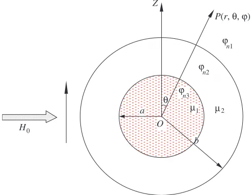
Assume that a uniform external magnetic field H0 passes through spherical space and surrounds the plasma of an object. Then, the magnetic permeability of the intermediate object isμ1, and the spatial distribution of plasma permeability is μ2. The inner and outer radii areaand b, as shown in Fig. 1.
H0
Z
O a
b
P(r, θ, ϕ)
θ
ϕn1
ϕn3 ϕn2
μ1 μ2
Figure 1. Space distribution model of spherical shells.
The scalar magnetic bits of each district are ϕn1,ϕn2, and ϕn3, all of which satisfy the following
Laplacian equations: ⎧
⎪ ⎨ ⎪ ⎩
∇2ϕ
n1= 0 (r > b) ∇2ϕ
n2= 0 (a < r < b) ∇2ϕ
n3= 0 (r < a)
. (1)
Their general solutions are ⎧ ⎪ ⎪ ⎪ ⎪ ⎪ ⎪ ⎪ ⎪ ⎪ ⎨ ⎪ ⎪ ⎪ ⎪ ⎪ ⎪ ⎪ ⎪ ⎪ ⎩
ϕn1 =
∞
n=0
Anrn+Bnr−(n+1)
Pn(cosθ) (r > b)
ϕn2 =
∞
n=0
Cnrn+Dnr−(n+1)
Pn(cosθ) (a < r < b)
ϕn3 =
∞
n=0
Enrn+Fnr−(n+1)
Pn(cosθ) (r < a)
Pn(cosθ) denotes the Legendre polynomials. An, Bn, Cn, Dn, En, and Fn are the coefficients of the general solutions. When the following boundary conditions are used: r = 0, ϕn3 is limited; r → ∞,
ϕn1 =−H0rcosθ;r =a,ϕn3=ϕn2,μ1∂ϕ∂rn3 =μ2∂ϕ∂rn2;r=b,ϕn1 =ϕn2,μ1∂ϕ∂rn1 =μ2∂ϕ∂rn2. The coefficients are calculated as follows:
⎧ ⎪ ⎪ ⎪ ⎪ ⎪ ⎪ ⎪ ⎪ ⎪ ⎪ ⎪ ⎪ ⎪ ⎪ ⎨ ⎪ ⎪ ⎪ ⎪ ⎪ ⎪ ⎪ ⎪ ⎪ ⎪ ⎪ ⎪ ⎪ ⎪ ⎩
A1=−H0
B1 =H0 μμ2 1 −
1
1 + 2μ2
μ1 b
3−a3/K
C1 =−3H0 1 + 2μμ2 1
/K
D1 =−2H0 μ2
μ1 − 1
a3/K
E1 =−9H0μμ2 1/K
F1 = 0
, (3)
whereK = (1 + 2μμ2 1)(2 +
μ2
μ1)−2(ab) 3(μ2
μ1 −1) 2.
When Eq. (3) is substituted into Eq. (2), Eq. (4) can be expressed as follows: ⎧ ⎪ ⎪ ⎪ ⎪ ⎪ ⎪ ⎪ ⎨ ⎪ ⎪ ⎪ ⎪ ⎪ ⎪ ⎪ ⎩
ϕn1 =−H0rcosθ+ HK0
2 μ2
μ1
2
− μ2
μ1
−1
b3−a3 cosθ
r2 (r > b)
ϕn2 =−3H0
K 1 + 2
μ2
μ1
rcosθ−3H0
K μ2
μ1 − 1
a3cosθ
r2 (a < r < b)
ϕn3 =−9H0
K μ2
μ1r
cosθ(r < a)
. (4)
The magnetic field strength of each region can be obtained from H =−∇ϕn.
3. NUMERICAL SIMULATION
3.1. Impacts of Internal and External Radii
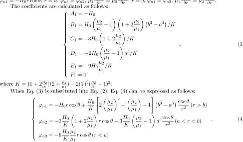
Assume that the magnetic field strength H0 is 10 A/m, μ2 ≈μ0 [14], μ1 ≈ 20μ0 [15], where μ0 is the vacuum permeability. The magnetic distribution diagrams of the magnetic field are calculated as shown in Fig. 2 by changing the kernel radiusaand plasma radius bas shown in Table 1.
Table 1. Different aand b parameters.
Computational Simulation
Number a/m b/m a/b
Simulation 1 1 4 1/4
Simulation 2 2 4 2/4
Simulation 3 3 4 3/4
Simulation 4 4 4 4/4
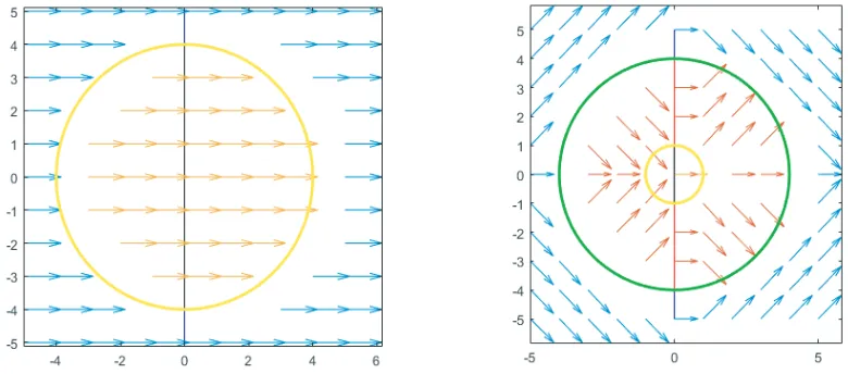
Simulation 1: Magnetic field distribution when a/b = 1/4 Simulation 2: Magnetic field distribution when a/b = 2/4
Simulation 3: Magnetic field distribution when a/b = 3/4 Simulation 4: Magnetic field distribution when a/b = 4/4
Figure 2. Simulations 1, 2, 3, and 4 that correspond to the magnetic field distribution.
3.2. Influence of Different Permeabilities
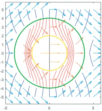
When the material of the magnet differs, the corresponding magnetic conductivity also varies. Assume that the magnetic field strength H0 is 10 A/m. Then, the values ofμ1 are provided in Table 2, and the distributions of magnetic fields are shown in Fig. 3.
The magnetic field on the plasma spherical shell is equivalent to a magnetic dipole in the external magnetic field. It is a superposition of a uniform field with a magnetic dipole. The magnetic dipole field is generated by the magnetic charge on the inner surface of the shell. Different μ2/μ1 ratios and the simulation of the magnetic field distribution are obtained as shown in Fig. 3 by changing the internal object material of the plasma spherical shell, i.e., with different magnetic permeabilities, as shown in Table 2. When μ2/μ1 is high, the magnetic field strength H3(r < a) and the magnetic field strength
Table 2. Experimental schemes with different magnetic permeabilities.
Computational Simulation
Number a/m b/m μ1
Simulation 1 2 4 0.1μ0
Simulation 2 2 4 μ0
Simulation 3 2 4 10μ0
Simulation 4 2 4 100μ0
Simulation 1: Magnetic field distribution when μ 2/μ 1= 10 Simulation 2: Magnetic field distribution when μ 2/μ 1= 1
Simulation 3: Magnetic field distribution when μ 2/μ 1= 0.1 Simulation 4: Magnetic field distribution when μ 2/μ 1= 0.01
Figure 3. Simulations 1, 2, 3, and 4 that correspond to the magnetic field distribution.
3.3. Analysis and Discussion
−→
H3 =−∇ϕn3 =
9−→H0 μ2
μ1
1 + 2μ2
μ1
2 + μ2
μ1
−2
a
b
3 μ2
μ1 − 1
2.
When μ2μ1,−→H3= 9
−→
H0 2µµ2
1[1−( a
b)3], the permeability ratio of μ1 and μ2 and the ratio of the internal and external radiiaandbhave a corresponding effect on the magnetic field in the inner space of the spherical shell. In other words, when the permeability of the spherical shell is large and the spherical shell is thick, the magnetic field in the inner space of the spherical shell, which provides the best shielding effect, is weak. The limit value of H3/H0 is 9/(2μμ21). The permeability of the plasma layer outside the object cannot approach 0; hence, achieving complete shielding effect is difficult.
3.4. Calculation Verification
The range of the radar electromagnetic wave is 2 ∼18 GHz; therefore, we use 8 GHz to calculate the magnetic field strength in 0.04 T. In 2005, Yang et al. used the calculation method for electromagnetic wave propagation in non-magnetized plasma to obtain the reflection coefficient of an electromagnetic field incident that exhibits vertical magnetism in magnetized plasma [16]. With different electromagnetic wave frequencies, the graph of the change in the total power reflection coefficient with the intensity of the magnetic field was calculated when the linearly polarized electromagnetic wave was incident on the magnetized plasma surface. The best magnetic field strengths of 0.04, 0.07, 0.14, and 0.18 T on the minimum electromagnetic wave reflection power correspond to electromagnetic wave frequencies of 8, 16, 24, and 32 GHz, respectively.
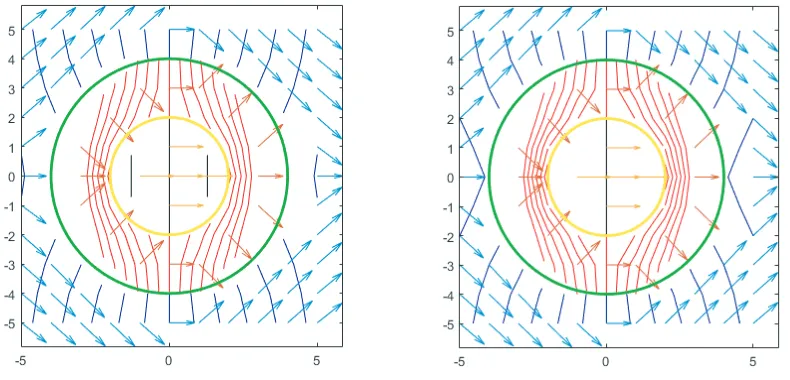
The permeability of plasma can still be regarded as equal to that of the vacuum. Common aerospace materials are used with aluminum alloy, magnesium alloy, alloy steel and composite materials. In Simulation 1 magnetic permeability μ1 = 40μ0, a = 4, and b = 4; in Simulation 2, permeability
μ1= 20μ0,a= 1, andb= 4. The calculations of the plasma spherical magnetic field around the object distribution are presented in Fig. 4.
Simulation 1: Magnetic field distribution when μ 2/μ 1= 0.025, a/b = 4/4 Simulation 2: Magnetic field distribution when μ 2/μ 1= 0.05, a/b = 1/4
Figure 4. Magnetic distribution map of each region in space of Simulations 1 and 2.
4. CONCLUSIONS
In this study, we use Laplacian equations in spherical coordinates and consider the ratio of the inner and outer radii of spherical shell plasma, and the size and permeability ratio of the plasma-wrapped object to perform modeling calculations. The magnetic field distribution of each region in spherical space is obtained and further deduced as follows.
When the scalar magnetic field of the external uniform magnetic field isH0, the magnetic charge of the plasma spherical shell is equivalent to a magnetic dipole on the outside of the magnetic shell.
The magnetic field in the plasma spherical shell is a superposition of a uniform field with a magnetic dipole field [17]. The uniform field is composed of an external uniform field and a uniform field generated by the magnetic charge on the outer surface of the ball. The magnetic dipole field is generated by the magnetic charge on the inner surface of the shell.
When μ2/μ1 is high and a/b is low, the ratio of the magnetic field strength H3 (region r < a) to the magnetic field strength H0 (region r > b) is low, and vice versa. When the magnetic permeability of the inner object is small and the spherical shell is thick, the produced plasma sheath is thick, and the external magnetic field in the inner space of the spherical shell is weak. Consequently, the “black barrier” phenomenon will exhibit good shielding effect and high possibility.
ACKNOWLEDGMENT
This project was financially supported by the National Natural Science Foundation of China (Nos. 10872044, 11672068, and 11672067) and the Fundamental Research Funds for Central Universities.
REFERENCES
1. Chen, F. F., Introduction to Plasma Physics, Plenum Press, New York and London, 1974.
2. Vidmar, R. J., “On the use of atmospheric pressure plasmas as electromagnetic reflectors and absorbers,”IEEE Transactions on Plasma Science, Vol. 18, No. 4, 733–741, 1990.
3. Laroussi, M. and J. R. Roth, “Numerical calculation of the reflection, absorption, and transmission of microwaves by a nonuniform plasma slab,”IEEE Transactions on Plasma Science, Vol. 21, No. 4, 366–372, 1993.
4. Mitchell, F. H., “Communication-system blackout during reentry of large vehicles,” Proceedings of the IEEE, Vol. 55, No. 5, 619–626, 1967.
5. Rybak, J. P. and R. J. Churchill, “Progress in reentry communications,” IEEE Transactions on Aerospace &Electronic Systems, Vol. 7, No. 5, 879–894, 1971.
6. Liu, J. F., X. L. Xi, and Y. Liu, “A solution to the propagation of electromagnetic wave in plasma sheath using FDTD method,”International Symposium on Antennas, 442–445, 2008.
7. Kim, M., M. Keidar, and I. D. Boyd, “Electrostatic manipulation of a hypersonic plasma layer: Images of the two-dimensional sheath,” IEEE Transactions on Plasma Science, Vol. 36, No. 4, 1198–1199, 2008.
8. Liu, J. F., X. L. Xi, G. B. Wan, and L. L. Wang, “Simulation of electromagnetic wave propagation through plasma sheath using the moving-window finite-difference time-domain method,” IEEE Transactions on Plasma Science, Vol. 39, No. 3, 852–855, 2011.
9. Hodara, H., “The use of magnetic fields in the elimination of the re-entry radio blackout,”
Proceedings of the IRE, Vol. 49, No. 12, 1825–1830, 1961.
10. Russo, F. P. and J. K. Hughs, “Measurments of the effects of static magnetic fields on vhf transmission in ionized flow fields,”NASA: Langley Research Center, 1964.
12. Keidar, M., M. Kim, and I. D. Boyd, “Electromagnetic reduction of plasma density during atmospheric reentry and hypersonic flights,” Journal of Spacecraft and Rockets, Vol. 45, No. 3, 445–453, 2008.
13. Kim, M., M. Keidar, and I. D. Boyd, “Two-dimensional modal of an electromagnetic layer for the mitigation of communication blackout,”47th AIAA Aerospace Sciences Meeting Including the New Horizons Forum and Aerospace Exposition, 092407, Orlando, Florida, 2009.
14. Tai, Y.-C. and S.-J. Fang,Electromagnetic Field and Electromagnetic Wave, 184, Dalian Maritime University Press, 2003 (in Chinese).
15. Zhang, X.-H., Manufacturing Technology and Practice, Vol. 22, Beihang University Press, 2011 (in Chinese).
16. Yang, J., L.-M. Zhu, W.-Y. Su, and G.-W. Mao, “Study on calculation of power reflection coefficient of electromagnetic wave on magnetized plasma surface,”Acta Physica Sinica, Vol. 54, No. 7, 3236– 3240, 2005.