Western University Western University
Scholarship@Western
Scholarship@Western
Electronic Thesis and Dissertation Repository
11-22-2016 12:00 AM
Characterization of N-butyl Cyanoacrylate (NBCA) Glue
Characterization of N-butyl Cyanoacrylate (NBCA) Glue
Polymerization for the Embolization of Brain Arteriovenous
Polymerization for the Embolization of Brain Arteriovenous
Malformations (AVMs)
Malformations (AVMs)
Bill H. Wang
The University of Western Ontario
Supervisor
Dr. Stephen P. Lownie
The University of Western Ontario
Graduate Program in Medical Biophysics
A thesis submitted in partial fulfillment of the requirements for the degree in Master of Science © Bill H. Wang 2016
Follow this and additional works at: https://ir.lib.uwo.ca/etd
Part of the Medical Biophysics Commons
Recommended Citation Recommended Citation
Wang, Bill H., "Characterization of N-butyl Cyanoacrylate (NBCA) Glue Polymerization for the Embolization of Brain Arteriovenous Malformations (AVMs)" (2016). Electronic Thesis and Dissertation Repository. 4271.
https://ir.lib.uwo.ca/etd/4271
This Dissertation/Thesis is brought to you for free and open access by Scholarship@Western. It has been accepted for inclusion in Electronic Thesis and Dissertation Repository by an authorized administrator of
II
Abstract:
Brain AVMs are abnormal connections between arteries and veins. Endovascular glue embolization
with NBCA is an accepted form of treatment. The reported complication rates of NBCA embolization
varies widely from 2-15%, and timing of polymerization plays a major role.
Polymerization time was measured for mixtures of lipiodol/NBCA of 50/50, 70/30, 60/40. The
influence of pH, temperature and presence of biological catalysts on polymerization time was
investigated in-vivo. PVA-C, silicone and endothelium surfaces were compared. High-speed video
analysis of glue injection through a microcatheter was performed.
Polymerization rate increases with pH and temperature. A hydrophilic surface such as PVA-C better
mimics endothelium. Biological substrates including endothelium and blood products dramatically
increase the polymerization rate. Characterization of coaxial flow shows dripping to jetting
transition with significant wall effect.
The determinants of NBCA polymerization rate are multifactorial and dependent mainly upon the
presence of biological substrates coupled with flow-related wall interaction.
Word count: 148
Keywords:
III
Acknowledgements
I would like to thank the following individuals for their support with this project
Thesis Supervisor:
Stephen P. Lownie, MD1,2,3
Thesis Advisory Committee:
Melfort Boulton, MD, PhD1,2,3
David Pelz, MD2
Gord Campbell, PhD3
Tamie Poepping, PhD3
Lab Coordinator:
Lynn Denning1
1. Department of Clinical Neurological Sciences, London Health Sciences Centre 2. Department of Medical Imaging, London Health Sciences Centre
Page | i
Table of Contents
Title Page ... I Abstract and Keywords ... II Acknowledgements ... III
Table of Contents ... i
List of Tables ... ii
List of Figures ... iii
List of Equation ... iv
List of Appendices... v
List of Abbreviations ... vi
General Introduction/Background ...1
Natural history of AVMs ... 1
Treatment of AVMs ... 2
Liquid embolic agent chemistry ... 4
Characteristic and factors that influence embolization – a brief analysis... 8
Distance between microcatheter tip and nidus ... 9
Glue mixture ... 9
Injection power... 10
Bibliography ... 15
Integrated Article: Characterization of NBCA (manuscript draft) ... 18
Background and hypothesis ... 18
Methods ... 19
Results ... 22
Discussion ... 28
Conclusion ... 31
Bibliography ... 33
Appendices ... 36
Page | ii
List of Tables
Table i. Morphologic and hemodynamic characteristics that influence embolization ... 8 Table 1.Effect of endothelium only on t0, t50and tcfor three glue formulations ... 26
Page | iii
List of Figures
Figure i. Chemical formula of cyanoacrylate monomers ... 5
Figure ii. Polymerization mechanism of cyanoacrylate ... 5
Figure iii. Chemical formula of Onyx ... 7
Figure iv. Example of vena contracta ... 11
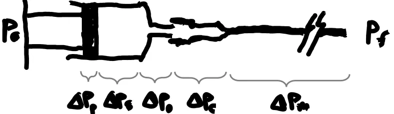
Figure v. Simplified diagram of the syringe/microcatheter system with labels ... 12
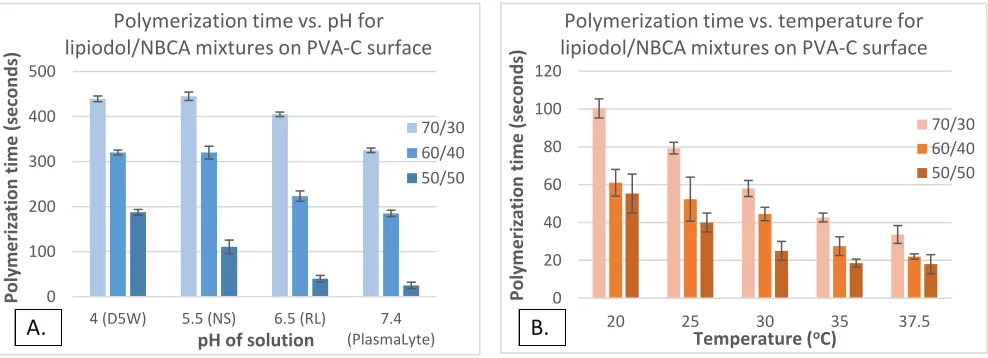
Figure 1. Polymerization time vs pH (A) and temperature (B) for three different formulations ... 22
Figure 2. Contact angle measurements between glue and difference surfaces ... 23
Figure 3. Contact angle measurements silicone, PVA-C and endothelial surfaces ... 23
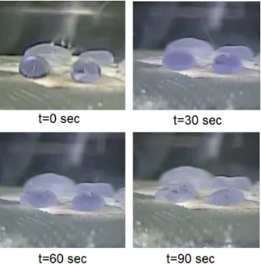
Figure 4. Endothelium catalyzes polymerization from the bottom-up ... 24
Figure 5. Indentation test on PVA-C surface at t=300sec ... 24
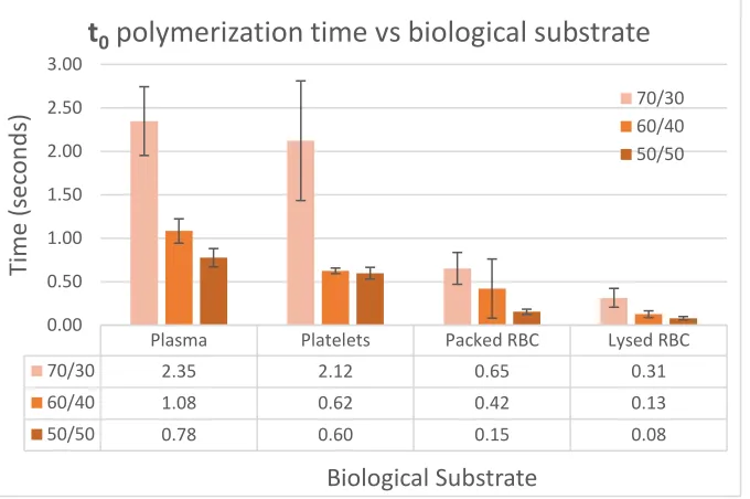
Figure 6. The effect of plasma, platelets, packed RBC and lysed RBC on to ... 25
Figure 7. The effect of plasma, platelets, packed RBC and lysed RBC on t50 ... 25
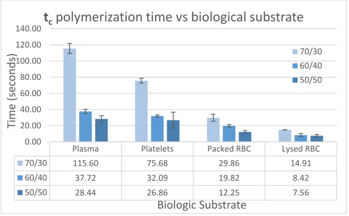
Figure 8. The effect of plasma, platelets, packed RBC and lysed RBC on tc... 26
Figure 9. t0, t50, and tc times for 70/30 glue formulation in plasma ... 27
Figure 10. t0, t50, and tc times for 60/40 glue formulation in lysed RBCs ... 27
Figure 11. Coaxial flow model adapted from Utada et al. ... 28
Figure 12. Screenshots of high speed video analysis of NBCA injection ... 28
Page | iv
List of Equations
Eq.1 Pouiselle flow equation ... 11
Eq.2 Overall pressure drop across the system ... 11
Eq.3 Pressure loss due to friction of the rubber plunger ... 12
Eq.4 Pressure drop terms for each subsection of the system ... 12
Eq.5 Pressure drop across the whole system in detail ... 13
Eq.6 Simplified system pressure drop in terms of applied force ... 13
Page | v
List of Appendices
Page | vi
List of Abbreviations
ANOVA – Analysis of variance
ASTM – American Society for Testing and Materials
AVM – Arteriovenous malformation
D5W – 5% dextrose in water (solution)
EVOH – Ethylene vinyl alcohol copolymer
FDA – Food and Drug Administration
NBCA – n-butyl cyanoacrylate
NS – Normal saline
PVA-C – Polyvinyl alcohol cryogel
RBC – Reb blood cell
RHV – Rotatable hemostatic valve
RL –Ringer’s lactate
SRS – stereotactic radiosurgery
Page | 1
General Introduction/Background
Natural history of AVMs:
Brain arteriovenous malformations (AVMs) are abnormal connections between arteries and veins
without an intervening capillary bed.[1, 2] The prevalence of brain AVMs in the general population
is not precisely known. Previous studies reported numbers that range from 2 to 20 per 100,000
people.[1-3] Some AVMs are asymptomatic while others are symptomatic and cause brain
hemorrhage (50%), seizures (40%), neurologic deficits (12%) and chronic headache (14%).[4]
Asymptomatic AVMs are discovered either incidentally during neurological imaging for unrelated
reasons or at the time of autopsy. Asymptomatic AVMs are more common with an estimated
prevalence of approximately 10-20 per 100,000 people.[1, 3] Symptomatic AVMs, on the other hand,
occur with a lower frequency of approximately 1-3 per 100,000 people.[2, 3]
Approximately half of all patients with symptomatic AVMs present with an intracerebral
hemorrhage.[4-6] In the pediatric population this number is even higher, approaching 80%.[7] Based
on natural history studies, the annual risk of hemorrhage from an AVM is around 2-4% per year.[6,
8-11] The biggest risk factor associated with AVM hemorrhage appears to be a history of prior
hemorrhage. AVMs that have ruptured have a higher re-rupture rate in the first year of 6-13%, and
the hemorrhage rate returns to baseline thereafter at 4% per year or lower.[4, 5, 8, 9, 11] Other
factors that increase the risk of hemorrhage include deep venous drainage, existence of associated
aneurysms, venous stenosis and deep/infratentorial location.[6, 8-11] AVM nidus size is an
inconsistent risk factor, with some studies showing smaller AVMs associated with higher risk of
hemorrhage while other studies showing larger AVMs to be more risky.[9, 11] Some studies looking
at AVM feeding artery pressure suggest that smaller AVMs are associated with higher feeder pressure,
offering a potential explanation for their higher risk of rupture.[12, 13] Larger AVMs, on the other
Page | 2 hemodynamic stresses, thereby providing an alternate explanation for their propensity to
rupture.[11, 13, 14]
Brain AVM rupture is a rare cause of intracerebral hemorrhage, accounting for 1.4-2% of all
hemorrhagic strokes;[1, 10, 15] however, in the young adult population (age 18 to 45), it accounts
for 25-35% of all hemorrhagic strokes.[6, 16] Hemorrhage is arguably the most serious problem
caused by AVMs, and it can have potentially life-threatening consequences for some patients.
Mortality after hemorrhage from a brain AVM is reported to be around 10% while residual major
disability occurs in 20%–30% of patients.[6, 8-11]
Treatment of AVMs:
Brain AVMs can be treated with open surgery, endovascular embolization, or radiation. All these
treatment modalities share a common goal, which is to obliterate the abnormal connections between
the feeding arteries and draining veins.[17, 18] Surgery provides the most direct approach, while
endovascular therapy attempts to disrupt blood flow to the nidus from within the feeding vessels.
Radiation, in the form of stereotactic radiosurgery (SRS), induces endothelial proliferation and
results in progressive nidus occlusion over time. Unlike surgery or embolization which exerts its
effect immediately, cure from SRS typically occurs slowly, exhibiting a plateau at 3-5 years out (up to
8 years in select patients). The AVM cure rate from SRS varies widely depending on a number
variables. In carefully selected patients, it could be as high as 70-80%.[19, 20] Interestingly,
endovascular embolization prior to SRS decreases the rate of occlusion at 3 years to approximately
40%.[19]
Symptomatic AVMs (hemorrhage or progressive neurologic deficit) are typically treated with surgery
and/or endovascular therapy. Endovascular embolization using liquid embolic agents is an accepted
form of treatment of brain AVMs.[18, 21] It is most often used as an adjunct to surgery to reduce
Page | 3 of cases.[18, 22] Previous authors have identified certain AVM characteristics associated with higher
likelihood of embolization cure such as: small AVM nidus size, less than 3 feeders and superficial
feeder/AVM location.[22] When these characteristics are used to screen patients, the cure rate of
brain AVMs with embolization alone is higher, ranging from 20% to over 50%.[21-26] This variability
is likely related to selection bias and to the lack of rigorous definition of embolization goals – i.e.
curative intent versus preoperative devascularization.[22]
Two liquid embolic agents have found widespread use in the clinical setting: N-butyl cyanoacrylate
(NBCA) and Ethylene vinyl alcohol copolymer (EVOH, known commercially as Onyx®). These are the
only FDA approved liquid embolic agents for neuro-interventional use. The reported complication
rate with NBCA embolization varies between 2% to 15%.[21, 23, 25] Hartmann et al. reported in their
series of 233 patients treated with NBCA embolization an overall complication rate of 14% and major
disability/mortality rate of 3%.[21] Some authors have suggested that most of the complications that
occur during embolization with NBCA are related to polymerization rate. [18, 21] A rate that is too
fast may cause proximal feeder artery occlusion. Glue could then reflux back into normal upstream
vessels, causing stroke. Conversely, a rate that is too slow could cause the glue to occlude the draining
vein, or embolize to the lung.[27] Premature venous drainage occlusion may raise the AVM intranidal
pressure and trigger intracranial hemorrhage.[24, 28, 29]
The scientific literature reports a wide range of polymerization rates with large discrepancies
between in-vivo and in-vitro results.[18, 30, 31] Furthermore, the interaction between glue and
vessel surface, as well as the presence of biologic catalysts are poorly understood. Despite its clinical
use for over 4 decades (FDA approved in 2000 with clinical use dating almost 3 decades prior), there
is still incomplete understanding of NBCA polymerization and injection behavior.[18] This has
resulted in large variability amongst authors with respect to glue concentration (typically modified
by altering glue/Lipiodol or glue/acetic-acid ratio) and the injection technique (sandwich, wedge or
Page | 4 Onyx (Covidien, USA) is becoming increasingly popular (FDA approved in 2003) amongst many
neuro-interventionalists due to its perceived margin of safety during injection. Onyx has a higher
viscosity and slower polymerization rate (more accurately, polymer condensation rate). Therefore,
injection can be made over a longer period of time than NBCA with time scales measured in minutes
rather than seconds.[18] However, the actual treatment morbidity and mortality is not significantly
lower compared to NBCA. Despite the lack of good quality randomized controlled trials, numerous
case series have reported overall complication rates between 1% and 17%.[22, 26, 32, 33] Katsaridis
et al. reported in their series of 101 AVMs treated with Onyx embolization an overall complication
rate of 11% and mortality rate of 3%.[26]
Onyx is unsuitable for high-flow lesions (e.g. AVMs with large fistulous components) because
polymerization must occur over a relatively short period of time. In addition, embolization with Onyx
in lenticulostriate or thalamoperforating arteries is associated with a high rate of complication (as
much as 50%[24]) and can only be accomplished with NBCA. The amount of NBCA operator
experience has gradually decreased since the introduction of Onyx. In situations where NBCA is the
only option for AVM embolization, the treatment risk for patients is further exacerbated given the
incomplete understanding of NBCA polymerization behavior.
Liquid embolic agent chemistry:
NBCA belongs to the family of cyanoacrylate glues which were first synthesized in 1949 and first
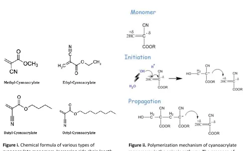
reported as a tissue adhesive about 10 years later.[34] Figure i. illustrates the chemical formula of
various types of cyanoacrylate monomers with different side chain groups (methyl, ethyl, butyl and
octyl).[35] The length of side chain determines the polymerization rate, with longer side chains
associated with a slower reaction rate. The final polymer formed also becomes more flexible and
more resistant to biological degradation as the side chain length increases. For biological use, butyl
Page | 5 mechanical matching of tissues and avoids the brittle polymer chains formed by methyl or ethyl
(Krazy Glue®) side chains. Cyanoacrylates decompose in the body via hydrolysis and methyl- or
ethyl-cyanoacrylates produce toxic break down products such as formaldehyde as well as eliciting
strong inflammatory reactions. Because of this, methyl- and ethyl-cyanoacrylates are not used for
biological purposes.[34]
Polymerization of cyanoacrylate monomers may occur via one of three mechanisms: anionic,
zwitterionic or free radical. Figure ii. shows the polymerization mechanism of the anionic pathway.
Of the three, the first two are strongly favored in-vivo due to the presence of hydroxide or amine
groups in the body to initiate the polymerization reaction.[34, 36] These groups also serve as binding
sites on proteins that allow strong bonds to form with cyanoacrylates.[37]
Figure ii. Polymerization mechanism of cyanoacrylate monomers via the anionic pathway. The presence of an anion such as OH- initiates the reaction and results
in chain polymerization.
Figure i. Chemical formula of various types of
Page | 6 NBCA has a rapid polymerization time and good tissue adherence, making it an effective agent for
sealing off abnormal vessel connections. However, this very property also makes it difficult to control
as described in the previous section. Additionally, the catheter tip may become glued to the vessel
wall, forcing the physician to leave a piece of the catheter behind. The ideal situation is for NBCA to
polymerize in the AVM nidus itself, thereby arresting all flow into the AVM.
Pure NBCA reacts extremely fast in-vivo and is almost never used except in pediatric Vein of Galen
malformations.[18] To decrease NBCA polymerization rate, various compounds can be added to
create glue mixtures. Acetic acid has been used as a polymerization retardant to slow down the
reaction mainly by decreasing the pH and the availability of anions such as OH-. Currently, most
centers use Lipiodol (ethiodized poppyseed oil) as both a radio-opaque agent and as a polymerization
retardant. However, the addition of lipiodol to NBCA slightly raises the mixture’s viscosity, requiring
greater injection force by the operator.[38] In the earlier years, tantalum powder was added as a
radio-opaque agent to allow visualization under fluoroscopy. However, some authors reported
spontaneous polymerization of NBCA-tantalum mixture when it was left unused for 15 minutes or
more.[31]
Typical mixtures of Lipiodol/NBCA encountered clinically are 50/50, 60/40, 70/30
(volume/volume). Increasing the amount of lipidol increases the polymerization time and conversely
decreases the polymerization rate. However, choosing the right formulation, injection rate and glue
volume is an imprecise science. To date, studies looking at the behavior of NBCA under physiological
conditions have been rather crude. Most interventionalists rely on experience and look at the
cerebral angiogram for clues. They determine the NBCA formulation based on nidus size, rate of
contrast clearance, number of feeding arteries and draining veins. The injection rate is a bit more
difficult to quantify, and most of the time it is an experienced “best guess”. In the full column
technique, once the glue is injected the catheter is quickly withdrawn to prevent adhesion of the tip
Page | 7 For comparison, the properties of Onyx will be briefly outlined below but will not be the focus of this
study. Onyx consists of a suspension of EVOH polymer in dimethyl sulfoxide (DMSO) with tantalum
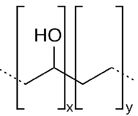
powder added for radio-opacity.[18] Figure iii. below shows the chemical formula of Onyx. It should
be noted that the polymer chains in Onyx suspension are already formed. Polymerization does not
actually occur since the suspension does not contain monomer units. Instead, upon injection, DMSO
quickly diffuses out of the suspension and EVOH precipitates into a soft rubbery mass in an aqueous
environment, resulting in vessel occlusion. The occlusion time measured during injection reflects
precipitation time rather than polymerization time. Onyx injections occur over the timespan of
minutes and may extend up to half-hour or more. In fact, a slow injection rate is encouraged since
prior animal work demonstrated that an overly vigorous injection can results in vessel tissue
dissolution by DMSO with potentially catastrophic consequences. Time is needed for DMSO to
dissolve and dilute into the bloodstream and surrounding interstitial tissue. Due to its slower rate of
action compared to NBCA, complications can arise in high-flow AVMs where Onyx embolizes to the
lungs. Although not an adhesive polymer, Onyx can also cause mechanical interference with the
microcatheter, resulting in difficult removal similar to NBCA.
Figure iii. Chemical formula of Onyx, with variable (x) number of vinyl alcohol groups and (y) number of ethyl groups. The polymer chains dissolve well in DMSO and remain in suspension. In an aqueous environment such as blood, the polymer chains are relatively hydrophobic and interact with each other strongly (via hydrogen
Page | 8
Characteristics and factors that influence embolization – a brief analysis:
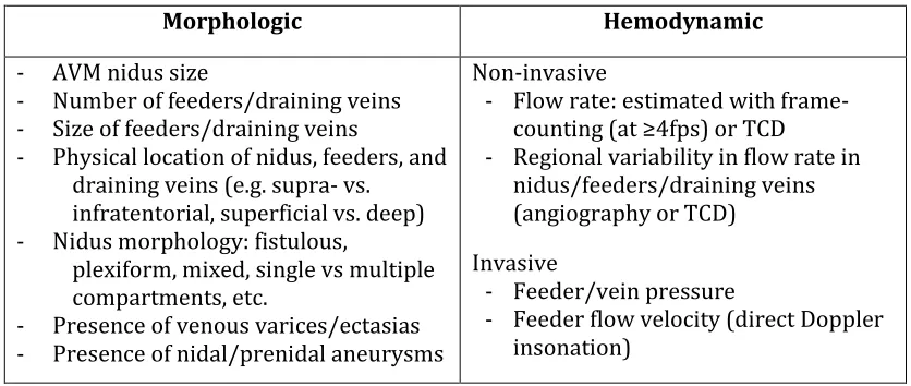
Characteristics: during embolization in the angiography suite there are several observable
characteristics intrinsic to the AVM which can be summarized as morphologic versus hemodynamic
(Table i).
Table i. Morphologic and hemodynamic characteristics that influence embolization
Morphologic Hemodynamic
- AVM nidus size
- Number of feeders/draining veins
- Size of feeders/draining veins
- Physical location of nidus, feeders, and
draining veins (e.g. supra- vs. infratentorial, superficial vs. deep)
- Nidus morphology: fistulous,
plexiform, mixed, single vs multiple compartments, etc.
- Presence of venous varices/ectasias
- Presence of nidal/prenidal aneurysms
Non-invasive
- Flow rate: estimated with
frame-counting (at ≥4fps) or TCD
- Regional variability in flow rate in
nidus/feeders/draining veins (angiography or TCD)
Invasive
- Feeder/vein pressure
- Feeder flow velocity (direct Doppler
insonation)
The morphologic characteristics tend to have an association with the likelihood of complete nidus
occlusion and complication rate as described in the previous section. The hemodynamic
characteristics predominantly provide indirect flow rate information. Together with morphologic
characteristics, they provide an indication of how quickly the glue needs to harden. Pressure
measurements may provide an indication of the risk of hemorrhage with partial embolization or
early vein occlusion, although the association is even less clear than the association with risk of
spontaneous hemorrhage.[12] Intravascular pressures are also observed to rise as the feeder and its
supplied nidus approach complete occlusion.[39]
Factors: In the angiography suite there appear to be a few modifiable factors that surgeons or
neuro-interventionalists can control during the embolization of AVMs. These include:
- The distance between the microcatheter tip and the AVM nidus
Page | 9
- The power of the injection
How each of these factors influence embolization will be outlined below.
Distance between microcatheter tip and nidus
The longer the distance between the microcatheter tip and the nidus, the longer the time the glue
needs to remain liquid. This information will need to be considered together with the estimated flow
velocity (typically observed using frame-counting) to provide a time estimate. The location of the
catheter tip may vary based on the injection technique. For example, a wedge technique would
require the catheter tip to be within the nidus and “wedged” against the wall. In this case, the distance
is essentially zero. In the full-column technique, the catheter tip will be parked in the feeder a short
distance away from the nidus. In addition to technique, there are often limitations as to how far the
catheter can be navigated. A very tortuous and/or distal feeder (e.g. distal anterior cerebral artery)
will limit how close the microcatheter tip can be advanced to the nidus.
Glue mixture
Changes in the NBCA/Lipiodol mixture changes the rate of polymerization. Interventionalists alter
this ratio based on how much time it is determined that the glue must remain liquid. This is described
in the paragraph above. The ultimate goal is to have as much of the glue polymerize within the nidus
as possible without premature occlusion of the feeding artery or draining vein. Currently, there is no
good data that accurately reflects the in-vivo polymerization time of various NBCA/Lipiodol mixtures
to help guide interventionalists. One of the objectives of this project is to generate such data to aid
interventionalists during embolization.
Since polymerization is a continuous process, polymerization times should be calculated for each
glue concentration at three different time points: t0, t50 and tc. t0 is the time to onset of polymerization,
first observed when the surface of the glue droplet opacifies and begins to deform. t50 is the time to
Page | 10
tc is the time to complete polymerization (or over 95% polymerization based on continuous video
observation). Distinction between the three time points is important because NBCA probably does
not need to reach tc for a significant change in AVM feeder to occur; it only need to be firm enough to
occlude the feeder.
Injection power
This factor includes a number of components. Power = Work/Time and Work = Force x Distance.
Looking at the relationship between a glue syringe and the interventionalist’s hand, force is applied
to the plunger which makes it travel a certain distance. This distance is directly related to the volume
of glue injected. The amount of force needed to do this will depend on the total resistance of the
syringe-microcatheter combination, the flow rate, as well as any additional downstream resistance
from feeding artery pressure or partially formed glue casts. The time it takes to perform the injection
will depend on both the injection velocity (how quickly the glue is pushed into the nidus) and the
total volume of glue used (more glue = more time pushing the syringe). Injection power captures all
of these variables into a single value, potentially allowing for objective quantification of
operator-dependent injection parameters.
Taking a closer look at the amount of force exerted, the syringe in the operator’s hand can be pushed
with a certain amount of force. The greater the force, the higher the flow rate. The overall resistance
of the system can be simplified to three factors:
1. Resistance from the syringe (different for 1cc vs 3cc)
2. Microcatheter Pouiselle flow resistance (see formula below)
3. Additional resistance from connectors and geometry changes
The size of the syringe has a direct effect on pressure (P) in the catheter since P = F/A, and for a given
force (F) applied by the operator, a smaller syringe will have a smaller cross-sectional area (A),
resulting in a greater pressure. This pressure will then cause greater volumetric flow rate (Q) based
Page | 11
∆𝑃 =8𝜇𝐿 𝜋𝑟4𝑄
Eq.1 Pouiselle flow equation: L=length of catheter, μ=dynamic viscosity, r=radius of catheter
If we examine the system in series the resistance acts in series. Starting with the applied pressure Pa
by the operator, there will be a pressure drop across the plunger due to plunger friction ∆Pp. Next,
there will be a pressure drop across the chamber of the syringe due to fluid resistance ∆Ps, which is
probably negligible but will be included in the initial analysis and expressed as a loss coefficient Cs.
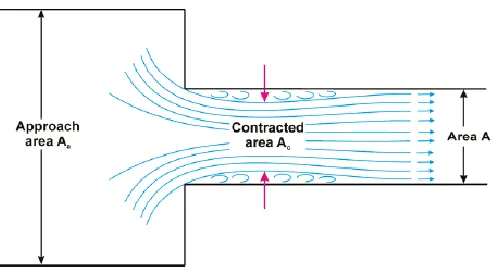
There will be a pressure drop across the syringe opening due to orifice effect (vena contracta, an
example is shown below in Figure iv.) ∆Po, which can be presented as a loss coefficient Co.
There will be a pressure drop across the connector hub of the microcatheter ∆Pc, which can also be
represented as a loss coefficient Cc. The pressure drop within the microcatheter ∆Pm is outlined below
and the final outlet pressure at the very tip of the microcatheter is Pf. If we add the pressure drops all
together, assuming the syringe is pushed slowly and the velocity inside is negligible, the total
pressure drop across the system can expressed as:
∆𝑃𝑠𝑦𝑠 = 𝑃𝑎− 𝑃𝑓
∆𝑃𝑠𝑦𝑠 = ∆𝑃𝑝+ ∆𝑃𝑠+ ∆𝑃𝑜+ ∆𝑃𝑐+ ∆𝑃𝑚
Eq.2 Overall pressure drop across the system
Page | 12
For ∆𝑃𝑝 if we imagine the plunger as a cylinder with radius rp and thickness t the pressure exerted
by the friction force of the plunger rubber against the syringe wall can be calculated as follows:
∆𝑃𝑝= 𝑓∗𝐹𝑛 𝜋𝑟𝑝2𝑡
Eq.3 Pressure loss due to friction of the rubber plunger against syringe wall, equation variables are outlined below.
Where f* is the coefficient of friction (either static or kinetic depending on the plunger motion), and
Fn is the radial normal force exerted by the plunger against the syringe wall. The coefficient of friction
will change depending on whether the injection is just starting where fs should be used versus if the
injection is under way where fk should be used instead. Practically speaking, it might be difficult to
ascertain f* ands Fn accurately, so the final value of ∆𝑃𝑝will probably need to be measured empirically.
The remaining pressure drop terms can be expressed as:
∆𝑃𝑠= 𝐶𝑠𝑄
∆𝑃𝑜 = 𝐶𝑜𝑄
∆𝑃𝑐 = 𝐶𝑐𝑄
∆𝑃𝑚 =
8𝜇𝐿 𝜋𝑟4𝑄
Eq.4 Pressure drop terms for each subsection of the system
Page | 13 Substituting the terms in equation 2 with equations 3 and 4 reveal the following equation:
∆𝑃𝑠𝑦𝑠 =
𝑓∗𝐹𝑛
𝜋𝑟𝑝2𝑡
+ 𝐶𝑠𝑄 + 𝐶𝑜𝑄 + 𝐶𝑐𝑄 +
8𝜇𝐿 𝜋𝑟4𝑄
𝑃𝑎=
𝑓∗𝐹𝑛
𝜋𝑟𝑝2𝑡
+ 𝐶𝑠𝑄 + 𝐶𝑜𝑄 + 𝐶𝑐𝑄 +
8𝜇𝐿 𝜋𝑟4𝑄 + 𝑃𝑓
𝐹𝑎
𝐴 =
𝑓∗𝐹𝑛
𝜋𝑟𝑝2𝑡
+ 𝐶𝑠𝑄 + 𝐶𝑜𝑄 + 𝐶𝑐𝑄 +
8𝜇𝐿 𝜋𝑟4𝑄 + 𝑃𝑓
Eq.5 Pressure drop across the whole system expressed in detailed terms.
There is the additional possibility to further simplify the equation by combining ∆Pp, ∆Ps and ∆Po into
a combined ∆Psyr as a pressure drop across the syringe and measure a combined loss coefficient Csyr.
Csyr would be best obtained empirically by working backwards and measuring the minimum force
needed to move the plunger in a filled syringe open to the atmosphere. An example of such a setup
could use a modified Harvard syringe pump with a load cell connected in series to measure the force
exerted by the pump at a certain plunger velocity. Substituting for this, we have:
𝐹𝑎
𝐴 = 𝐶𝑠𝑦𝑟𝑄 + 𝐶𝑐𝑄 + 8𝜇𝐿 𝜋𝑟4𝑄 + 𝑃𝑓
Eq.6 Simplified system pressure drop expressed in terms of applied force by the interventionalist.
In the event that the flow deviates from ideal assumptions (i.e. non-laminar flow, can be checked by
calculating the Reynold’s number𝜌𝑣𝐿
𝜇 ), the more generalized Darcy-Weisbach equation can be used
instead of Pousielle equation. If we were to also take into account the fluid velocity within the syringe
then the application of Bernoulli’s equation and continuity equation would be more appropriate and
the loss terms will then depend on Q2 instead of Q. Doing so would yield the following, assuming effect
of gravity is negligible:
𝑃𝑎− ∆𝑃𝑝
𝜌𝑔 +
𝑉02
2𝑔= 𝑃1
𝜌𝑔+ 𝑉12
2𝑔+ (𝑓 𝐿 𝐷+ Σ𝐾)
𝑉12
2𝑔
Page | 14
The pressure inside the syringe is expressed by the Pa– ∆Pp and the average velocity of the fluid
moving inside the syringe is V0. P1 and V1 denotes the pressure and velocity at the end of the
microcatheter right before the fluid exits into the blood stream. K is the aggregate loss coefficient
from the two step-down contractions at the syringe nozzle and at the converging connector (confuser
geometry) to the microcatheter. It is well known from experimental studies that pressure losses at
contractions are dependent on downstream velocity only (i.e. V1). The average velocities can be
converted to volumetric flow rates (Q) based on the simple equation Q = VA, where V is the average
velocity and A is the cross-sectional area. For Q0 the area of the syringe plunger is used and for Q1, the
cross-sectional area of the inner lumen of the microcatheter is used.
Finally, it is worth noting that the exit condition in the blood stream is dependent on the difference
in velocity between the free stream and the catheter glue flow as well the difference in viscosity
between the two mediums. This can be best described as a co-axial flow scenario where the outer
shell flow consists of blood and the inner stream injected into this shell flow (also known as bulk flow)
consists of NBCA/Lipiodol mixture. Idealized flow studies have shown an important transition from
dripping to jetting flow depending on the difference in velocity and viscosity.[40] In the real-world
scenario, wall interaction and polymerization (transformation from liquid to solid) during injection
further complicates the analysis.
The analysis above serves as a conceptual framework when considering the variables involved in
the injection of liquid embolic agents during treatment of brain AVMs. In the present study, the
interaction between glue, vessel wall and bulk flow will be characterized via simulated in-vivo
injections. The remaining parts of the aforementioned analysis will not be explored due to scope
and time constraints. The analysis lays the foundation for future work and will be part of another
Page | 15
Bibliography
1 Stapf C, Mast H, Sciacca RR, et al. The New York Islands AVM Study: Design, Study Progress, and Initial Results. Stroke 2003;34:29 doi:10.1161/01.STR.0000068784.36838.19.
2 Berman MF, Sciacca RR, Pile-Spellman J, et al. The epidemiology of brain arteriovenous malformations. Neurosurgery 2000;47:389-97 doi:10.1097/00006123-200008000-00023.
3 Al-Shahi R, Fang JSY, Lewis SC, et al. Prevalence of adults with brain arteriovenous malformations: a community based study in Scotland using capture-recapture analysis. Journal of neurology, neurosurgery, and psychiatry 2002;73:547-51 doi:10.1136/jnnp.73.5.547.
4 Hofmeister C, Stapf C, Hartmann A, et al. Demographic, Morphological, and Clinical Characteristics of 1289 Patients With Brain Arteriovenous Malformation. Stroke 2000;31:1307-10
doi:10.1161/01.STR.31.6.1307.
5 da Costa L, Wallace MC, ter Brugge KG, et al. The Natural History and Predictive Features of Hemorrhage From Brain Arteriovenous Malformations. Stroke 2009;40:100-5
doi:10.1161/STROKEAHA.108.524678.
6 Mast H, Young WL, Koennecke H, et al. Risk of spontaneous haemorrhage after diagnosis of cerebral arteriovenous malformation. The Lancet 1997;350:1065-8 doi:10.1016/S0140-6736(97)05390-7.
7 Kondziolka D, Humphreys RP, Hoffman HJ, et al. Arteriovenous malformations of the brain in children: a forty year experience. Can J Neurol Sci 1992;19:40-5.
8 Crawford PM, West CR, Chadwick DW, et al. Arteriovenous malformations of the brain: natural history in unoperated patients. Journal of Neurology, Neurosurgery, and Psychiatry 1986;49:1-10 doi:10.1136/jnnp.49.1.1.
9 Graf CJ, Perret GE, Torner JC. Bleeding from cerebral arteriovenous malformations as part of their natural history. Journal of neurosurgery 1983;58:331-7 doi:10.3171/jns.1983.58.3.0331.
10 Rangel-Castilla, Russin, Martinez-del-Campo, et al. Molecular and cellular biology of cerebral arteriovenous malformations: a review of current concepts and future trends in treatment. Neurosurgical Focus 2014;37 doi:10.3171/2014.7.FOCUS14214.
11 Abecassis IJ, Xu DS, Batjer HH, et al. Natural history of brain arteriovenous malformations: a systematic review. Neurosurgical focus 2014;37:E7.
12 Spetzler RF, Hargraves RW, McCormick PW, et al. Relationship of perfusion pressure and size to risk of hemorrhage from arteriovenous malformations. Journal of neurosurgery 1992;76:918-23 doi:10.3171/jns.1992.76.6.0918.
Page | 16 14 Norbash AM, Marks MP, Lane B. Correlation of pressure measurements with angiographic
characteristics predisposing to hemorrhage and steal in cerebral arteriovenous malformations. AJNR. American journal of neuroradiology 1994;15:809.
15 Novakovic RL, Lazzaro MA, Castonguay AC, et al. The diagnosis and management of brain arteriovenous malformations. Neurologic clinics 2013;31:749.
16 Carmine Marini, Tommasina Russo, Giorgio Felzani. Incidence of Stroke in Young Adults: A Review. Stroke Research and Treatment 2011;2011:1-5 doi:10.4061/2011/535672.
17 Cognard C, Forsting M. Intracranial vascular malformations and aneurysms. Berlin ; Heidelberg: Springer 2008.
18 Ardelt AA, Deveikis JP, Harrigan MR. Handbook of cerebrovascular disease and neurointerventional technique. New York [u.a.]: Springer 2013.
19 Xu F, Zhong J, Ray A, et al. Stereotactic radiosurgery with and without embolization for intracranial arteriovenous malformations: a systematic review and meta-analysis. Neurosurgical focus 2014;37:E16.
20 Pollock BE, Storlie CB, Link MJ, et al. Comparative analysis of arteriovenous malformation grading scales in predicting outcomes after stereotactic radiosurgery. J Neurosurg 2016:1-7 doi:10.3171/2015.11.JNS151300.
21 Hartmann A, Pile-Spellman J, Stapf C, et al. Risk of Endovascular Treatment of Brain Arteriovenous Malformations. Stroke 2002;33:1816-20
doi:10.1161/01.STR.0000020123.80940.B2.
22 Potts MB, Zumofen DW, Raz E, et al. Curing arteriovenous malformations using embolization. Neurosurgical focus 2014;37:E19.
23 Li TL, Fang B, He XY, et al. Complication analysis of 469 brain arteriovenous malformations treated with N-butyl cyanoacrylate. Interventional neuroradiology : journal of peritherapeutic neuroradiology, surgical procedures and related neurosciences 2005;11:141-8.
24 Lownie S. Clinical and Technical Complications of Endovascular Therapy in the Central Nervous System. Semin intervent Radiol 1993;10:243-53 doi:10.1055/s-2008-1074727.
25 Yu SCH, Chan MSY, Lam JMK, et al. Complete Obliteration of Intracranial Arteriovenous Malformation with Endovascular Cyanoacrylate Embolization: Initial Success and Rate of Permanent Cure. American Journal of Neuroradiology 2004;25:1139.
26 Katsaridis V, Papagiannaki C, Aimar E. Curative embolization of cerebral arteriovenous malformations (AVMs) with Onyx in 101 patients. Neuroradiology 2008;50:589-97 doi:10.1007/s00234-008-0382-x.
Page | 17 28 Handa T, Negoro M, Miyachi S, et al. Evaluation of pressure changes in feeding arteries during embolization of intracerebral arteriovenous malformations. Journal of neurosurgery 1993;79:383-9 doi:10.3171/jns.1993.79.3.0383.
29 Nornes H, Grip A. Hemodynamic aspects of cerebral arteriovenous malformations. Journal of neurosurgery 1980;53:456-64 doi:10.3171/jns.1980.53.4.0456.
30 Kailasnath P, Chaloupka JC. Quantitative Assessment of Polymerization-Binding Mechanics of Cyanoacrylates: Model Development and Validation. American Journal of Neuroradiology 2002;23:772.
31 Brothers MF, Kaufmann JC, Fox AJ, et al. n-Butyl 2-cyanoacrylate--substitute for IBCA in
interventional neuroradiology: histopathologic and polymerization time studies. American Journal of Neuroradiology 1989;10:777.
32 van Rooij WJ, Sluzewski M, Beute GN. Brain AVM embolization with Onyx. AJNR. American journal of neuroradiology 2007;28:172.
33 van Rooij WJ, Jacobs S, Sluzewski M, et al. Curative embolization of brain arteriovenous malformations with onyx: patient selection, embolization technique, and results. AJNR. American journal of neuroradiology 2012;33:1299.
34 Kohane D. Tissue Adhesives as Active Implants. In: Anonymous . Active Implants and Scaffolds for Tissue Regeneration. Berlin, Heidelberg: Springer Berlin Heidelberg 2011:39-56.
35 Kyle P Davis, Robert W Derlet. Cyanoacrylate glues for wilderness and remote travel medical care. Wilderness & environmental medicine 2013;24:67-74 doi:10.1016/j.wem.2012.08.004.
36 Vauthier C, Dubernet C, Fattal E, et al. Poly(alkylcyanoacrylates) as biodegradable materials for biomedical applications. Advanced Drug Delivery Reviews 2003;55:519-48 doi:10.1016/S0169-409X(03)00041-3.
37 Jeppsson MC, Mörtstedt H, Ferrari G, et al. Identification of covalent binding sites of ethyl 2-cyanoacrylate, methyl methacrylate and 2-hydroxyethyl methacrylate in human hemoglobin using LC/MS/MS techniques. Journal of Chromatography B 2010;878:2474-82
doi:10.1016/j.jchromb.2010.04.026.
38 Bracard S, Macho-Fernández JM, Wang X, et al. Influence of temperature on embolisation with cyanoacrylate. Interventional neuroradiology : journal of peritherapeutic neuroradiology, surgical procedures and related neurosciences 1998;4:301.
39 Duckwiler G, Dion J, Vinuela F, et al. Intravascular microcatheter pressure monitoring: experimental results and early clinical evaluation. American Journal of Neuroradiology 1990;11:169.
Page | 18
Integrated Article: Characterization of NBCA – Manuscript Draft
Target Journal: Journal of NeuroInterventional Surgery (JNIS)
Title: A systematic characterization of the factors influencing polymerization and dynamic behavior of n-butyl cyanoacrylate (NBCA)
Bill H. Wang1, David M. Pelz1,2, Melfort R. Boulton1,2, Donald H. Lee1,2, Stephen P. Lownie1,2
1. Department of Clinical Neurological Sciences, London Health Sciences Centre
2. Department of Medical Imaging, London Health Sciences Centre
Background and objective:
Brain arteriovenous malformations (AVMs) are abnormal connections between arteries and veins
without an intervening capillary bed.[1, 2] Their prevalence ranges from 1 to 20 per 100,000 patients,
and of these, approximately half will present with an intracerebral hemorrhage resulting in
significant morbidity (30-40% per event) and mortality (10% per event).[1-6] Endovascular glue
embolization with injection of N-butyl cyanoacrylate (NBCA) is an accepted form of treatment.[7-10]
It is most often used as an adjunct to surgery or radiosurgery, although it can be sufficient as a
standalone treatment in approximately 5-10% of cases.[8] In carefully selected cases the cure rate
with endovascular embolization can be higher, ranging from 20% to 50%.[7, 11-15]
Although ethylene vinyl alcohol copolymer (EVOH, sold by Covidien as Onyx®) has quickly become a
preferred liquid embolic agent at many centers, there are certain high-flow AVMs (usually with
fistulous components) where Onyx cannot be used due to the risk of passage into the venous outflow
system. This typically results from inadequately fast polymer precipitation rate to match the AVM
flow rate. NBCA remains a mainstay of treatment in such situations but is also associated with
complications. Most of the complications that occur during embolization with NBCA are related to
polymerization rate.[7, 8] A rate that is too fast may cause proximal feeding artery occlusion. Glue
could then reflux back into normal upstream vessels, causing stroke. Conversely, a rate that is too
lung.[16-Page | 19 18] Premature venous drainage occlusion may raise the AVM intranidal pressure and trigger
intracranial hemorrhage. [19-21]
Existing scientific literature reports a wide range of polymerization rates with significant
discrepancies between in-vivo and in-vitro results.[8, 22, 23] Furthermore, the interaction between
glue and vessel surface, as well as the presence of biologic catalysts are poorly understood. Therefore,
despite its clinical use for over 4 decades (FDA approved in 2000 with use dating almost 3 decades
prior)[9, 10], there is still incomplete understanding of NBCA polymerization and injection
behavior.[8] This has resulted in wide variation with respect to the degree of dilution (typically
modified by altering glue/Lipiodol or glue/acetic-acid ratio)[24] and injection technique (sandwich,
wedge or full-column technique) used for NBCA embolization procedures.[7, 8]
The decreasing amount of NBCA operator experience with the introduction of Onyx coupled with the
incomplete understanding of NBCA behavior further exacerbates treatment risk for patients,
especially in situations where NBCA is the only option. In this study, we aim to systematically
characterize the factors that influence NBCA polymerization in both static and dynamic
environments. Such information could help interventionalists to optimize injection parameters and
potentially reduce complications.
Methods:
From previous studies[8, 22-25] and our preliminary data, NBCA appears to behave differently in the
presence of biological tissue compared to tissue-free vessel substitutes. NBCA interactions were
deconstructed into three categories: influence of physical parameters (namely temperature and pH);
physical interaction between NBCA and vessel wall (both non-biological and biological); and
influence of exposure to biological tissue.
The influence of pH and temperature on NBCA polymerization time was measured. The submerged
Page | 20 inert PVA-C surface (confirmed through preliminary work) and continuously monitored via
high-definition video recording system. The glue was kept submerged in an aqueous environment to
simulate the physical conditions during embolization. Polymerization time was measured for
clinically relevant mixtures of Lipiodol/NBCA of 50/50, 60/40, 70/30 ratios (NBCA was mixed with
Lipiodol to provide radio-opacity and to delay polymerization). Polymerization times were recorded
for solution pH values of 4, 5.5, 6.5 and 7.4 at temperature of 37.4oC. This corresponded to physiologic
solutions of D5W, normal saline, Ringer’s lactate, and Plasma-Lyte® respectively. These solutions
provided an aqueous acellular and plasma-free environment. Polymerization times were also
recorded for solution temperature values of 15, 20, 25, 30, 35 and 37.5oC at pH of 7.4 (Plasma-Lyte®
solution used).
The physical interaction between NBCA and the vessel wall was analyzed using the contact angle
method with the important modification of performing all measurements in a submerged aqueous
environment. Native avian endothelium was used as the reference surface and droplets of NBCA
(~0.1cc) were carefully placed on the flattened vessel surface using a syringe with a 25-gauge needle.
Silicone (both plain and heparin coated) and poly-vinyl alcohol cryogel (PVA-C) surfaces were tested
as vessel substitutes and compared to the endothelial surface. Silicone was chosen due to its ubiquity
and its status as a “de facto” vessel substitute in numerous prior studies involving NBCA. PVA-C was
chosen as a hydrophilic material that better replicates the physical properties of an endothelial
surface. All tests were carried out under physiologic conditions (pH 7.4, temperature 37.5oC) in an
acellular and plasma-free environment.
To delineate the role of potential biological catalysts, the endovascular environment was separated
into endothelial surface and blood products. The effect of endothelial surface was assessed by placing
NBCA droplets on a flattened viable (<6 hours from time of harvest) endothelial surface while
video-recording the polymerization reaction. The effect of blood products was further broken down into
Page | 21 measured by first placing a layer of each of the respective blood products on a PVA-C (inert) surface,
followed by placing NBCA droplets onto the surface. All tests were performed in an aqueous
environment at pH of 7.4 and temperature of 37.5oC. Since polymerization is a continuous process,
polymerization times were calculated for each glue concentration at three different time points: t0,
t50and tc. t0 is the time from initial glue deposition to the onset of polymerization, first observed when
the surface of the glue droplet opacifies and the droplet just begins to deform. t50 is the time to
achieve a 50% change in height of the glue droplet (or 50% reduction in diameter in any direction).
tc is the time to near-complete polymerization (or over 95% polymerization based on continuous
video observation).
Visual assessment of polymerization was performed based on video recording footages.
Frame-by-frame analysis (video recorded at standard 30fps) was performed to accurately calculate t0, t50and
tc times. To further confirm that near-complete polymerization had truly occurred at tc, we
performed indentation tests on select glue droplets using an ASTM type OO indenter with a modified
10-gram load. This allowed us to assess whether the center of the glue droplet still remained liquid
once the outer shell had opacified.
Finally, to examine the dynamic behavior of NBCA/Lipiodol mixture in an AVM feeding artery during
microcatheter injection, high-speed video analysis of glue injection was performed to characterize
flow and simulate in-vivo conditions. A flow circuit was constructed using a pulsatile pump with
tubing connected to straight vessel substitutes made of heparin coated silicone (Medtronic, USA).
Heparin coating improves surface hydrophilicity compared to plain silicone while providing
transparency for high-speed video recording. A flow bypass circuit was connected parallel to the
vessel substitute. This allowed the pressure and flow rates to be adjusted to match conditions
typically encountered in an AVM feeder. A rotating hemostatic valve (RHV) was connected upstream
Page | 22 NBCA/Lipiodol flow within the vessel was considered akin to co-axial flow as described by Utada et
al, with a transition from “dripping” to “jetting” as the outer shell (blood) flow increased.[26]
At least 3 droplets were used for each glue formulation/test condition combination. Statistical
significance was determined using a two-tailed Student’s t-test, ANOVA or chi-squared analysis
wherever appropriate. Results are expressed as mean +/- Standard Deviation (SD). Results are
considered significant when P < 0.05.
Results:
pH and Temperature: The polymerization times for three different formulations of Lipiodol/NBCA
(referred from here on in as “glue” for simplicity) are plotted against pH and temperature in Figures
1A and 1B respectively. Polymerization time decreased (indicating increasing polymerization rate)
with increasing pH as well as increasing NBCA glue concentration. Both pH and glue formulation
independently influenced polymerization time and their effects are statistically significant based on
2-factor ANOVA. The influence of temperature on polymerization rate is plotted in Figure 1B.
Although the brain is at body temperature during interventional procedures, the catheters are
constantly flushed with ambient temperature solution. As such, the AVM nidus temperature could
actually be slightly below body temperature. As expected from reaction kinetics, increasing
Figure 1. Polymerization time vs pH (A) and temperature (B) plots for three different mixtures of lipiodol/NBCA
0 100 200 300 400 500
4 (D5W) 5.5 (NS) 6.5 (RL) 7.4 (PlasmaLyte) P oly m er izati on ti m e (seco n d s)
pH of solution
Polymerization time vs. pH for lipiodol/NBCA mixtures on PVA-C surface
70/30 60/40 50/50
A.
0 20 40 60 80 100 12020 25 30 35 37.5
Poly m e ri zation tim e ( sec o n d s)
Temperature (oC)
Polymerization time vs. temperature for lipiodol/NBCA mixtures on PVA-C surface
70/30 60/40 50/50
Page | 23 temperature caused a corresponding increase in polymerization rate. Both temperature and glue
formulation also independently influenced polymerization time with statistical significance (2-factor
ANOVA).
NBCA – Vessel Wall interactions: The submerged contact angle of glue droplets on silicone (52±3o,
Figure 2A), heparin coated silicone (84±3o, Figure 2B) and PVA-C (150±8o, Figure 2C) were markedly
different from each other (pairwise comparisons using two-tailed Student’s t-test all resulted in
p<0.05). The contact angle between glue and endothelium was found to be 151±3o (Figure 2D). There
was no statistically significant difference in contact angle between endothelial and PVA-C surfaces.
However, the difference between the endothelial and the two silicone surfaces were significantly
different (Figure 3). There was no statistically significant difference in contact angle for a given
surface between various glue formulations (50/50, 60/40 and 70/30, data not shown).
Biological Catalysts: From previous studies[8, 22-25] and our own observations, glue polymerization
rate increases in the presence of biological tissue. Figures 4 shows time-lapse photographs of glue
droplets (60/40 formulation) on an endothelial surface (pH=7.4, 37.5oC). Figure 5 shows glue
droplets (60/40 formulation) on a PVA-C surface at 5 minutes after initial placement and
Figure 2. Contact angle measurements between NBCA/Lipiodol and difference surfaces submerged in D5W at 37.5oC: silicone, silicone with heparin coating
PVA-C and endothelium surfaces
A. Silicone
C. PVA-C
D. Endothelium
B. Silicone +Hepa.
Page | 24 confirmatory indentation test to assess extent of polymerization. Glue droplets on both surfaces
started out at t=0 seconds looking identical with similar appearances to those shown in Figure 2C
and 2D. However, as time progressed the glue droplets on the endothelial surface started
polymerizing from the bottom-up. This directional preference caused the droplet to flatten out over
time with complete polymerization occurring at approximately t=90 seconds. In contrast to this, the
glue droplets on the PVA-C surface (Figure 5) opacified and flattened somewhat initially but then
changed very little as time went on. Indentation test was performed at t=300 seconds on glue
droplets on the PVA-C surface. Despite the glue droplets’ optical appearance, their centers never truly
polymerized even after 300 seconds. This was demonstrated by the blue liquid glue streak running
between the polymerized shell and the type OO indentor tip.
The decomposition of the endovascular environment yielded the following major biological
components: endothelium, plasma, platelet and RBC. Their effect on glue polymerization time was
further explored. Given that polymerization is a continuous process, the times to, t50and tc were
calculated for each glue formulation and biological substrate combination as shown in Figures 6-8.
Figure 4. Endothelium catalyzes polymerization from the bottom-up, effectively flattening the droplet as polymerization approach tc of
approximately 90 seconds
Page | 25 Table 1 shows the polymerization times for glue droplets on an endothelial surface. Overall,
polymerization times decreased as the biological substrate varied from endothelium, plasma,
platelets, packed RBC and lysed RBC. Lysed RBC appear to result in the greatest decrease in
polymerization time (corresponding to the greatest increase in polymerization rate) as
demonstrated based on the measured values of to, t50and tc.
Plasma Platelets Packed RBC Lysed RBC
70/30 2.35 2.12 0.65 0.31
60/40 1.08 0.62 0.42 0.13
50/50 0.78 0.60 0.15 0.08
0.00 0.50 1.00 1.50 2.00 2.50 3.00
Tim
e
(s
ec
on
d
s)
Biological Substrate
t
0polymerization time vs biological substrate
70/30 60/40 50/50
Plasma Platelets Packed RBC Lysed RBC
70/30 7.45 6.02 4.08 2.20
60/40 4.80 3.90 2.77 0.80
50/50 3.23 3.30 0.62 0.45
0.00 1.00 2.00 3.00 4.00 5.00 6.00 7.00 8.00 9.00
Tim
e
(s
ec
on
d
s)
Biological Substrate
t
50polymerization time vs biological substrate
70/30 60/40 50/50
Figure 6. The effect of plasma, platelets, packed RBC and lysed RBC on the time to onset of polymerization t0 for various glue formulations
Page | 26
Table 1. Effect of endothelium (no blood products) on polymerization times t0, t50and tc for various glue formulations, measured in seconds
Glue: 50/50
Glue: 60/40
Glue: 70/30
t
00.6 ± 0.3
1.6 ± 0.4
13 ± 3
t
508 ± 2
72 ± 6
614 ± 31
t
c98 ± 4
416 ± 6
1880 ± 68
Figure 9 shows an example of polymerization time measurements for 70/30 glue formulation upon
exposure to plasma. The glue appeared transparent upon initial deposition at t = 0 seconds. At t0 =
2.4 seconds the glue droplet opacified and began to deform, providing a visual indication of the start
of polymerization. At t50=7.5 seconds the glue droplet flattened to approximate 50% of the original
height and appeared more irregular due to ongoing polymerization. Finally, at tc = 116 seconds
polymerization was complete and the glue droplet lost its bluish hue while taking on an irregular
multi-lobulated morphology. Figure 10 shows the exposure of 60/40 glue formulation to lysed RBC
which resulted a very fast polymerization time. t0 occurred almost instantaneously at 0.13 seconds
and t50 was achieved at only 1 second after glue deposition. Complete polymerization occurred after
approximately 8 seconds with the glue cast exhibiting a similar white irregular appearance as Figure Plasma Platelets Packed RBC Lysed RBC
70/30 115.60 75.68 29.86 14.91
60/40 37.72 32.09 19.82 8.42
50/50 28.44 26.86 12.25 7.56
0.00 20.00 40.00 60.00 80.00 100.00 120.00 140.00
Tim
e
(s
ec
on
d
s)
Biologic Substrate
t
cpolymerization time vs biological substrate
70/30 60/40 50/50
Page | 27 9. The polymerization time was so rapid that the NBCA droplet did not have sufficient time to detach
from the depositing needle, polymerizing at the tip.
In Vivo Simulation: Figure 11 illustrates the idealized model of coaxial flow as previously described
by Utada et al. The outside shell flow is akin to the blood flow in an AVM feeding artery while the
central coaxial flow mimics the microcatheter glue injection. As the injection rate increased, there
appeared to be a transition from dripping to jetting flow.[26] Figure 12 shows the experimental
observations (recorded at 240fps), where three distinct phases are noted. Phase 1 (12A) consisted
of dribble flow that lasted only 1-2 seconds before the whole microcatheter was filled with NBCA.
Phase 2 (12B) continued as jetting flow (short jet) with length of jet dependent on outer shell flow
velocity and vessel diameter. Phase 3 (7C) occurred when NBCA wetted the vessel wall and continued
to roll off the vessel wall, sending droplets downstream so long as the glue remained liquid. Phase 3
was not described by Utada et al.8 since their model assumed the injection catheter to be in the middle
of the vessel, free from any wall-effect. Based on our observations, during endovascular
microcatheter injections, it is more common to have the microcatheter tip against the wall or pointed
at an angle towards the wall.
Figure 10. t0, t50, and tc times for 60/40 glue
formulation during exposure to lysed RBCs
Figure 9. t0, t50, and tc times for 70/30 glue formulation
Page | 28
Discussion:
In this study, we sought to systematically characterize the factors that influence NBCA
polymerization in both static and dynamic environments. The effect of pH and temperature on glue
polymerization time is known. However, a detailed quantification of their effect on glue
polymerization has not been previously reported. Exposure to anions is the most common way to
initiate polymerization in cyanoacrylates. Anions act as electron donors to initiate the reaction. Once
initiation occurs, chain propagation will continue spontaneously for variable lengths.[27] The
hydroxide (OH-) anion is ubiquitous in aqueous environments, present whenever there is H2O. In the
clinical setting, prior to glue injection the microcatheter is thoroughly flushed with D5W (5%
dextrose solution) with the common explanation that D5W does not contain any ions. From a basic
chemistry stand point, this is false since all solutions will contain ions. It is the relative concentration
of these ions that will influence polymerization time, and D5W happens to be the most acidic isotonic
solution used clinically with a pH of 4. This translates to the lowest concentration of OH- groups
available of any solution, resulting in the best prevention against polymerization.
The physical interaction of glue with different surfaces provides some caution in interpreting in-vitro
flow studies in existing scientific literature. Silicone is often used as a de-facto vessel substitute in
flow models. However, the behavior of glue on silicone is quite different from that of endothelium.
Figure 11. Coaxial flow model[26]
Figure 12. Screenshots of high speed video analysis of NBCA injection illustrating an initial period of dribbling flow (A, <1sec) followed by short jetting flow (B, 1-2 sec). Wall-effect eventually takes over (C) at variable time point depending on microcatheter position (typically starting at approximately 3 seconds).
A
B
Page | 29
Glue tends to spread more easily and stick to a silicone surface more readily, effectively “coating” it
due to the shallow contact angle. This reduces glue flow velocity compared to the average bulk flow
velocity and gives glue more time to polymerize in the silicone tubing. Therefore, studies employing
silicone flow models to study glue embolization may over-estimate the effect of glue polymerization
(especially in the absence of any biological tissue) in achieving flow arrest.[28]
As a mock vessel surface, PVA-C provided the closest mimicry of endothelium. However, due to the
lack of any catalytic activity, it was paradoxically more difficulty to achieving flow arrest when
injecting glue into PVA-C tubing. During polymerization, glue would form strong chemical bonds with
the endothelial surface (based on our observations) that could act as anchor points. Glue did not bond
to PVA-C readily, further exacerbating the flow arrest problem. In-vitro studies that employ mock
vessels with hydrophilic surfaces should be interpreted in light of these findings.
The effects of biological substrates on glue polymerization time is significant and may help explain
some of the discrepancies in previous studies that measured the polymerization time of NBCA in the
in-vitro setting. In one of the earliest papers, Stoesslein et al. measured the in-vitro polymerization
rate of NBCA/Lipiodol mixtures by bringing it into contact with citrated blood on a cover glass slip
and visually observing polymerization.[24] The authors did not further specify the criteria used to
judge polymerization, although the values that they published appeared closer to tc. Brothers et al.
used a very different in-vitro method where glue droplets were dripped into human plasma held in
a transparent cup with a piece of newspaper underneath it.[23] Opacification of the newspaper
letters was defined as polymerization time, which is likely in between t0 and t50. Interestingly, both
authors noted that vivo studies seemed to result in faster polymerization times compared to
in-vitro results.
A few explanations were entertained to explain the in-vitro/in-vivo discrepancy, such as mixing
Page | 30 this study, it was fortuitous that Stoesslein et al. used whole blood as a biologic catalyst (albeit
unknowingly). However, their values were closer to tc(3.2, 4.7 and 7.5 seconds for 50/50, 33/66 and
25/75 formulations respectively) than t50 since they were measuring near-complete polymerization.
Brothers et al. on the other hand used plasma, which would give a slower polymerization rate.
However, they chose opacification as the polymerization end point which occurs quite early as seen
in Figures 4, 5, 9 and 10. This provided partial offset to the slower polymerization time in plasma and
the study ended up with values (0.7, 2.5, 3 and 4 seconds for 100/0, 50/50, 33/66 and 25/75
formulations respectively) that were closer to t50 in pRBC.
In the in-vivo setting, glue polymerization cannot be measured directly, and operators must use other
clues such as nidus penetration or flow arrest as surrogate measures. This depends not only on
polymerization time, but also on nidus morphology. Polymerization times may seem faster in-vivo
for two reasons: 1. The presence of biologic substrates (especially RBCs) and 2. Interference from
nidus or proximal feeders that allows partially polymerized glue to change/block flow before tc is
reached. It is for the second reason that we measured not only tc, but also t0 and t50. Looking at the
values of t50, they appear to better approximate the time scales encountered clinically during
embolization of AVMs (where contrast filling of the nidus can occur as quickly as 0.25 – 0.5 seconds).
Glue does not need to fully polymerize to exert its effect, it just has to be hard enough to plug part of
the nidus or feeding artery for stasis to occur.
Exposure to lysed RBC appears to result in the fastest glue polymerization time. The exact reason for
this is unknown. It is known that amine groups from proteins can act as electron donors to initiate
polymerization via a zwitterion
ic
mechanism.[27] Cyanoacrylates have also been shown to formcovalent bond with proteins (i.e. protein adducts) upon exposure to biologic tissue.[29] Cell
membrane components and charge probably do not fully explain this since both endothelium and