Design of a Wireless Power Transfer System to Power Wireless
Sensors Remotely Using UHF
Sungkyun Lim1, *, Deon Lucien1, Joshua Haney1, Jinxi Chen2, Rakibul Islam1, and Cameron Cato3
Abstract—A wireless power transfer system is designed to power remotely placed wireless sensors using UHF band. For receiving purpose, a small and compact, bi-quad antenna is designed which has a fractional bandwidth of 6.89% (443.65 MHz–475.5 MHz). The receiver antenna is uni-directional and has the maximum gain of 9.7 dBi. The overall dimensions of the antenna including the reflective ground plane are 50 cm×30 cm×16 cm (0.767λ×0.46λ×0.172λat 460 MHz). A General Mobile Radio Service (GMRS) radio license is obtained and a frequency of 462.55 MHz is used during the test measurement. The maximum achieved effective distance is 150 ft with 3.52 V, which is enough for powering most of the commercial sensors.
1. INTRODUCTION
Wireless power transfer (WPT) has fascinated scientists and engineers since the early 20th century. The first conceptual attempt was carried out using tesla coils to transfer power without the use of a conductive medium by Nikola Tesla [1]. Unfortunately, no information exists as to how much power was able to transmit and recover. During the 1950s and 60s the development of high-power microwave transmitters, and the invention of the first solid-state semiconductor diodes capable of operating at microwave frequencies led to further developments in WPT. With the use of these new technologies the Raytheon cooperation developed the first rectenna, and demonstrated a wirelessly powered helicopter. While the helicopter flight was highly publicized, the high-power transmitter and large dipole array need to transfer sufficient power made the system impractical for commercial or military use. However, these developments lead to continual wireless power research and the solar power satellite concept [2].
In the recent era of far-field WPT, interest has shifted from high-powered microwave power beaming to low power WPT systems for the remote powering of electronic sensors, for use in applications such as industrial plant monitoring, structural monitoring, and implanted medical device monitoring [3]. Previously, several WPT systems utilizing microwave energy harvesting have been proposed [4–6]. In these systems ambient RF energy is collected using a broadband microwave rectenna or rectenna array. Sources of microwave energy for salvaging include cell phone towers, ultra-high frequency (UHF) TV transmitters, along with 2.5 and 5.8 GHz Wi-Fi devices [7]. For rural areas in which ambient microwave energy is insufficient for harvesting, low power (< 1 watt) transmitters operating in the industrial, scientific and medical(ISM) bands have been proposed [8]. Due to the variable power densities available to the rectenna, many energy harvesting designs integrate power control modules which limit the duty cycle at transmitter based on available power [9]. A recent study demonstrates the use of the Cockcroft-Walton multiplier along with different input powers [10]. While suitable for a variety of applications such as structural monitoring, the variable duty cycle transmitters could cause problems, particularly in
Received 10 April 2019, Accepted 26 June 2019, Scheduled 6 July 2019
* Corresponding author: Sungkyun Lim ([email protected]).
1 Department of Electrical and Computer Engineering, Georgia Southern University, Statesboro, GA 30460, USA.2 TDK Corp. of
the monitoring of industrial equipment and processes. Additionally, the use of a power control module adds cost and complexity to the wireless sensor.
In this paper a new far-field wireless power transfer system is proposed for the remote powering of wireless sensors. The proposed WPT system differentiates itself from both high-power wireless power beaming, and wireless energy harvesting systems through the use of a medium power transmitter, operating in the UHF business band (450–470 MHz). The UHF business band provides longer propagation range than microwave frequencies yet still permits the construction of antennas small enough to be installed alongside wireless sensors in an industrial setting. The Business band also lacks the power restrictions common with the use of ISM bands. To enable the powering of a distributed network of sensors the proposed system uses an omni-directional power transmission antenna instead of the directional, narrow-beamwidth antennas used in wireless power beaming. Due to the higher amount of available RF energy in the proposed system, a power management module is not needed, reducing the total system cost and allowing the use of fixed duty cycle transmitter.
2. SYSTEM OVERVIEW
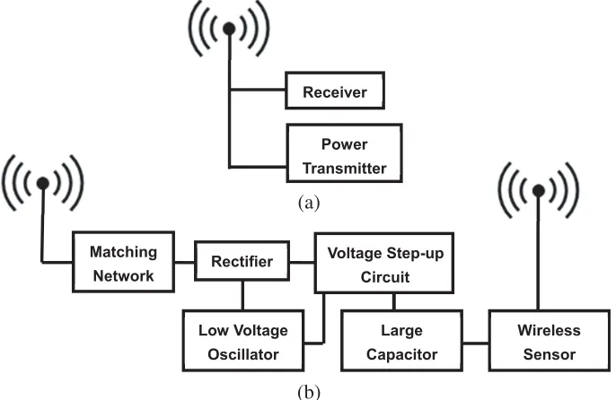
The block diagram of the proposed WPT system is shown in Figure 1. Figure 1(a) displays the wireless power transmitter. The wireless power transmitter is designed to supply a continuous source of RF energy to all surrounding wireless power receivers. The wireless power transmitter consists of a transmitter tuned to the proper UHF business band frequency and a high gain omni-directional collinear antenna to maximize received power. For use in industrial setting, the power transmitter is placed at a high location, visible to all wireless power receivers. Care should be taken to restrict maximum transmit power to maintain compliance with FCC maximum permissible exposure limits (as example maximum transmit power at 902–928 MHz band is 36 dBm EIRP) [9].
Receiver
Power Transmitter
Matching
Network Rectifier
Voltage Step-up Circuit
Low Voltage Oscillator
Large Capacitor
Wireless Sensor (a)
(b)
Figure 1. Schematic diagram of WPT system. (a) Transmitter. (b) Receiver.
the wireless power receiver is stored in a large value capacitor [11]. During transmission the capacitor supplies sufficient current to the wireless sensor, recharging between transmission cycles.
3. POWER RECEPTION ANTENNA
When evaluating antenna designs for use in the proposed UHF WPT systems numerous criteria were considered. The antenna should be relatively small and compact, allowing for mounting beside wireless sensors. For easy installation in industrial environments, the antenna should allow for direct mounting against walls and other objects regardless of the material composition. The antenna should have sufficient bandwidth to cover the UHF business band. Finally, the antenna should have high gain to maximize power transfer. Considering these criteria the bi-quad antenna was chosen for integration into the proposed system [12].
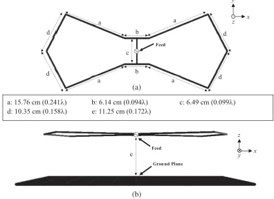
In Figure 2, the geometry of an optimized bi-quad antenna is depicted with two rhombic loops fed in parallel. Each loop is approximately one wavelength long. The loops are placed approximately a quarter wavelengths above a reflective ground plane. The antenna is fed with a coaxial cable attached to the center of the antenna. Detailed dimensions are also shown in Figure 2. The antenna is optimized using a genetic algorithm (GA) for maximum realized gain in the zenith direction (opposite of thez direction in Figure 2) while maintaining a small geometry at a frequency of 460 MHz. The overall dimensions of the antenna including the reflective ground plane are 50 cm×30 cm×16 cm (0.767λ×0.46λ×0.172λ).
a a
b
b
a a
c
d d d
d
Feed
e
a: 15.76 cm (0.241λ) b: 6.14 cm (0.094λ) c: 6.49 cm (0.099λ) d: 10.35 cm (0.158λ) e: 11.25 cm (0.172λ)
Feed
Grou nd Plane
x y
z
x y z
.
(a)
(b)
Figure 2. Optimized bi-quad antenna. (a) Top view with no ground plane, (b) side view with ground plane.
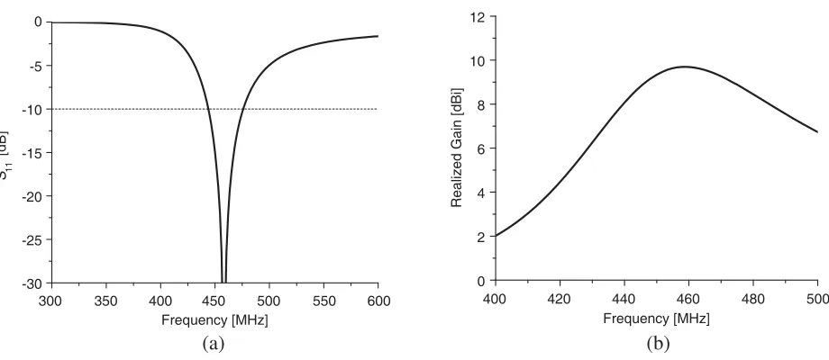
The simulated S11 and realized gain of the optimized bi-quad antenna are presented in Figure 3.
-30 -25 -20 -15 -10 -5 0
0 2 4 6 8 10 12
Realized Gain [dBi]
(a) (b)
300 350 400 450 500 550 600
Frequency [MHz]
400 420 440 460 480 500
Frequency [MHz]
S
[dB]
11
Figure 3. SimulatedS11 and realized gain. (a)S11, (b) realized gain.
-40 -30 -20 -10 0
0
-30
-20
-10
0
[dB]
30
60
90
120
150 180
210 240 270
300 330
XZ plane
YZ plane
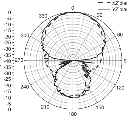
Figure 4. Simulated radiation pattern at 460 MHz.
Figure 5. Prototype of the optimized bi-quad antenna.
polarization is also studied. The maximum gains for the XZ and Y Z cross polarizations are −77 dBi and −79 dBi, respectively. Compared to the co-polarization, the cross polarization fields are negligible. The prototype of the antenna is fabricated as shown in Figure 5. Figure 6 shows the measured S11 and realized gain of the optimized bi-quad antenna. The measured−10-dB bandwidth is 443.65–
477.69 MHz (7.16%). The maximum measured realized gain is 10.3 dBi at a frequency of 463.50 MHz. Despite a slight upward shift in frequency, both the measured S11 and realized gain agree well with
simulated data. The antenna is usable over the entire UHF business band.
Figure 7 shows the measured radiation pattern of the proposed antenna. The measured 3-dB beamwidth is 48◦ and 68◦ for the XZ and Y Z cut respectively. Both the measured XZ and Y Z radiation patterns agree fairly well with the simulated data.
4. RECTIFIER AND MATCHING NETWORK
-30 -25 -20 -15 -10 -5 0
0 2 4 6 8 10 12
Realized Gain [dBi]
(a)
(b)
300 350 400 450 500 550 600
Frequency [MHz]
400 420 440 460 480 500
Frequency [MHz]
S
[dB]
11
Figure 6. MeasuredS11 and realized gain. (a) S11, (b) realized gain.
0
30
60
90
120
150 180
210 240
270 300
330
XZ plane
YZ plane
-40 -30 -20 -10 0
-30
-20
-10
0
[dB]
-5
-15
-25
-35
-5 -15 -25 -35
Figure 7. Measured radiation pattern at 463.50 MHz.
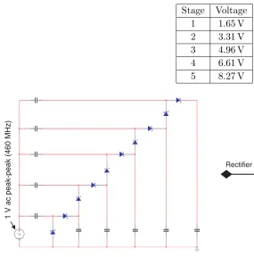
Table 1. Output at different stage of multiplier for 1 V input.
Stage Voltage
1 1.65 V
2 3.31 V
3 4.96 V
4 6.61 V
5 8.27 V
1 V ac peak-peak (460 MHz)
Figure 8. Cockcroft-Walton multiplier.
L1
C1
Antenna Rectifier
Figure 9. Schematic diagram of L-matching network.
-30 -25 -20 -15 -10 -5 0
360 380 400 420 440 460 480 Frequency [MHz]
S
[dB]
11
500 520 540
Figure 10. MeasuredS11 of rectifier.
Matching Network
Figure 11. Picture of prototype rectifier with integrated matching network.
rectifier’s impedance, 22.2−j5.2 Ω, in calculation. Considering the effect of the FR4 material of the PCB board and parasitic effect of the lumped elements, after performing the trial and error method a series inductance of 6.82 nH and a shunt capacitance of 7.54 pF were found to provide a match of 50 +j0 Ω at a frequency of 462 MHz. The measured S11 of the completed rectifier and matching network is shown
UHF business band. A picture of the completed rectifier and integrated matching circuit is shown in Figure 11.
5. SYSTEM TESTING AND MEASUREMENT
After testing of the individual components in the WPT system, the entire system is tested and evaluated. For short time testing purpose of the proposed WPT system, a General Mobile Radio Service (GMRS) radio license is obtained and a frequency of 462.55 MHz is used during the test. A Baofeng UV-5R transceiver is used and the transmitter output is set at 4 W. Instead of omni-directional high gain antenna, a collinear antenna with a gain of 9 dBi is used for the transmitter.
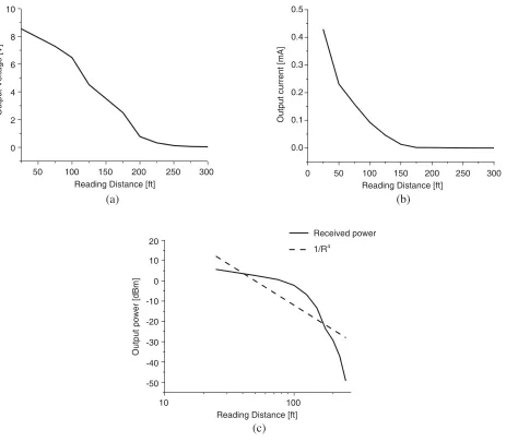
In the receiver side, the rectifier with the matching circuit is connected directly with the receiver antenna to minimize the cable losses. A voltmeter is used to record voltage as the system is moved further from the transmitter. When the receiver in close proximity of about 25 ft, the achieved output voltage is as high as 8.7 V. In addition, the maximum effective distance is 150 ft with 3.51 V is achieved, which is enough to run commercial wireless sensors. The output current and power are added in Figures 12(b) and (c), respectively. As seen in Figure 12(c), the output power roughly follows the transmission path loss near a large ground plane, 1/R4, according to the Friis transmission model. The maximum effective distance can be further improved by increasing radiated power from the transmitter.
0 2 4 6 8 10
0.0 0.1 0.2 0.3 0.4 0.5
(a) (b)
(c)
50 100 150 200 250 300
Reading Distance [ft]
50 100 150 200 250 300
Reading Distance [ft] 0
100 Reading Distance [ft] 10
Output Voltage [V]
Output current [mA]
Output power [dBm]
20
10
0
-10
-20
-30
-40
-50
Received power
1/R4
The power efficiency of the antenna is not studied due to the negligible difference in efficiency at long distances [15].
6. CONCLUSIONS
A WPT system is proposed to remotely power wireless sensors. To receive power efficiently a highly directive small and compact size bi-quad antenna is designed and optimized. The receiver antenna bandwidth was 6.89% (443.65 MHz–475.50 MHz), which is within the UHF band, and the maximum gain of the antenna is achieved as 9.7 dBi at 460 MHz. A rectifier circuit is designed with an impedance matching circuit to match the impedance with receiver antenna. The maximum achieved distance for effective power transfer is 150 ft with 3.51 V, which is enough for powering most of the commercial sensors.
ACKNOWLEDGMENT
This work was supported by Southern Company and Georgia Power.
REFERENCES
1. Brown, W., “The history of power transmission by radio waves,” IEEE Trans. Microwave Theory
Tech., Vol. 32, No. 9, 1230–1242, 1984.
2. McSpadden, J. O., F. E. Little, M. B. Duke, and A. Ignative, “An in-space energy transmission experiment,” Proc. 31st Intersociety Energy Conversion Eng. Conf. (IECEC), Vol. 1, 468–473, 2004.
3. Paing, T., A. Dolgov, J. Shin, J. Brannan, R. Zane, and Z. Popvic, “Wirelessly powered wireless sensor platform,” European Microwave Conf., 241–244, 2007.
4. Kim, S., et al., “Ambient RF energy-harvesting technologies for self-sustainable standalone wireless sensor platforms,”Proceedings of the IEEE, Vol. 102, No. 11, 1649–1666, Nov. 2014.
5. Vera, G. A., A. Georgiadis, A. Collado, and S. Via, “Design of a 2.45 GHz rectenna for electromagnetic (EM) energy scavenging,”IEEE Radio and Wireless Symposium, 61–64, Jan. 2010. 6. Hagerty, J. A., F. B. Helmbrecht, W. H. McCalpin, W. R. Zane, and Z. B. Popovic, “Recycling ambient microwave energy with broad-band rectenna arrays,” IEEE Trans. Microwave Theory
Tech., Vol. 52, No. 3, 1014–1023, 2004.
7. Pinuela, M., P. Mitcheson, and S. Lucyszyn, “Ambient RF energy harvesting inurban and semi-urban environments,” IEEE Trans. Microwave Theory Tech., Vol. 61, No. 7, 2715–2726, 2013. 8. Kim, Y.-J., H. S. Bhamra, J. Joseph, and P. P. Irazoqui, “An ultra-low-power RF energy-harvesting
transceiver for multiple-node sensor application,”IEEE Trans. Circuit and Systems, Vol. 62, 1028– 1032, 2015.
9. Le, T., K. Mayaram, and T. Fiez, “Efficient far-field radio frequency energy harvesting for passively powered sensor networks,” IEEE J. Solid-State Circuits, Vol. 43, 1287–1302, 2008.
10. Fan, S., et al., “A 2.45-GHz rectifier-booster regulator with impedance matching converters for wireless energy harvesting,”IEEE Trans. Microwave Theory Tech., 1–11, 2019.
11. Liu, X., P. Wang, P. C. Lou, F. Gao, and F. H. Choo, “Control of hybrid battery/ultra-capacitor energy storage forstand-alone photovoltaic system,”IEEE Energy Conversion and Exposition, 336– 341, 2010.
12. Tsukiji, T. and S. Tou, “On polygonal loop antennas,” IEEE Trans. Antennas Propag., Vol. 28, 571–575, 1980.
13. https://www.digikey.com/products/en?WT.z se ps=1&keywords=1N6263. 14. Pozar, D. M., Microwave Engineering, 4th Edition, Wiley, New York, 2011.
15. Kumar, S., S. De, and D. Mishra, “RF energy transfer channel models for sustainable IoT,”IEEE