DESIGN AND DEVELOPMENT OF SET-UP FOR
GREASE FILLING MACHINE
Prof. Dandage Rahul
1, Mr. Sawant Akshay
2, Mr. Kushwaha Vivek
3, Mr.
Salvi Aoudumber
41
Asst. Prof.
2,3,4UG Students, Mechanical Engineering, RMCET, Ambav,( India)
ABSTRACT
An engineer is always focused towards challenges of bringing ideas and concepts to life. Therefore,
sophisticated machines and modern technique have to be constantly developed and implemented for economical
manufacturing of products. At the same time, we should take care that there has been no compromise made with
quality and accuracy.
In the age of automation, machine became an integral part of human being. By the use of automation, machine
proves itself that it gives high production rate than manual production rate. In competitive market everyone
wants to increase their productivity & make the machine multipurpose.
The engineer is constantly conformed to the challenges of bringing ideas and design into reality. New machines
and techniques are being developed continuously to manufacture various products at cheaper rates and high
quality.
This paper discusses about making a set up for maintenance ofLHB Roller Bearing which can be used in future
as fully automated for lubrication purpose. The basic objective is it should be simple to maintain and easy to
operate.
Keywords: Grease filling, LHB, Lubrication, Roller Bearing, Sophisticated.
I. INTRODUCTION
LINKE HOFMANN BUSCH (LHB) is a railway Coach Manufacturing unit situated at Germany. Thecoaches
manufactured by LHB are called LHB coaches. These coaches are now being manufactured at Rail Coach
Factory,Kapurtala after getting the Transfer of technology from Germany. These LHB coaches are superior to
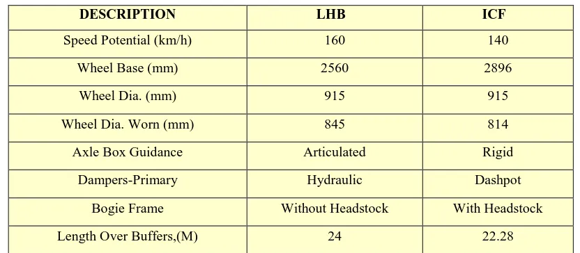
Table 1 Difference between LHB Coaches with ICF Coaches
DESCRIPTION LHB ICF
Speed Potential (km/h) 160 140
Wheel Base (mm) 2560 2896
Wheel Dia. (mm) 915 915
Wheel Dia. Worn (mm) 845 814
Axle Box Guidance Articulated Rigid
Dampers-Primary Hydraulic Dashpot
Bogie Frame Without Headstock With Headstock
Length Over Buffers,(M) 24 22.28
The process of maintenance for LHB bearings is not done in Western Railway Workshop at Lower Parel,
Mumbai.Hence a lot of time is consumed in the transportation for maintenance work. Anotherissue is of manual
grease filling process which leads to inaccuracy in distribution of grease on Cartridge Taper Roller
Bearing(CTRBs). In order to overcome from these problems, we are designing & making the set-up for grease
filling machine in Western Railway Workshop.
It will be beneficial for the maintenance of LHB bearing which was earlier done by external vendors. By means
of this project the overall maintenance cost is reduced. Normally for refurbishment of CTRB's time taken is of
20-25 days by bearing manufacture company which will be reduced to 2-3 days by implementing this project.
The major benefits are reduction in maintenance cost &time required for maintenance.
II. NEED OF LUBRICATION FOR BEARINGS
The life of any bearing depends to a great extent on the proper lubrication of the bearing. Lubricants aid in
carrying away heat, protecting bearing surfaces from corrosion and reducing friction.
Statistics show that nearly 50 percent of all bearing damage can be attributed to inadequate lubrication.
Although a very broad term, inadequate lubrication can be classified into eight basic categories:
Over-filling,
Under-filling,
Incorrect grease,
Mixing greases,
Incorrect lubrication systems and intervals,
Wornout grease,
Water contamination, and
Debris contamination.
The two categories which can appear due to improper grease filling are discussed here.
2.1 Over-Filling-
Over-filling a bearing with too much grease can cause excess churning of the grease during operation and high
generated cannot dissipate correctly, continually building until damage occurs. As the operating temperature of
the bearing rises, the oxidation rate of the grease sharply increases – doubling every 18º F.
During initial start-up, it is common for a properly lubricated bearing to purge a small amount of grease. A
slight grease purge is often recommended by original equipment manufacturers, as it acts as a barrier seal to
help keep out external debris contamination. Always original equipment manufacturers’ recommendations
regarding grease purging and correct replenishment amounts should be followed.
An overfilled bearing may also purge grease during initial start-up. However, over time and as temperature
rises, excess grease will continue to purge from an overfilled bearing and have a darkened color.
Grease undergoing heavy oxidation often has a very distinguishable black color and burned odor. In addition, it
gets stiffer in composition.
2.2 Under-Filling-
Under-filling a bearing with grease can also have adverse consequences. As in overfilling, heat can be generated
but for different reasons. When the grease amount is low, a grease starvation condition may be created, causing
heat generation or excessive metal wear during operation. If a bearing suddenly becomes noisy and/or the
temperature increases, excessive wear may be taking place.
III. EXISTING BEARING MAINTENANCE PROCESS AT WESTERN RAILWAY
WORKSHOP
IV. DESIGN CALCULATIONS
Power of Shaft = 17 watt
Power transmitted by shaft,
P= (2πNT)/60
Where, N = 24
T= 6.76 x 10³ N-mm
We know that,
N1 = 12 ; N2 = 36
Ratio = R = 1:3
Torque on sprocket = 3 × T
= 20.280 x 10³ N-mm
Diameter Of sprocket,
Periphery = π × dia. Of sprocket
36 × 6.25 = π × D
D = 72 mm
Torque transmitted,
T = Force × radius
20.280 x 103 =F× 36
F = 563.33N
F = 563.33/9.81
F = 58 Kg
Torque transmitted by shaft,
T = π/16 x τ x d3
Select permissible shear stress (τ) from design data book.
τ = 70 N/mm2
Therefore, 20.28 x 103 = π /16 x d3 x 70
D = 12 mm.
Taking factor of safety = 1.6
D = 1.6 x 12 =19.2 = 20 mm
We select dia. Of shaft = 20mm.
NOMENCLATURE
P = Power of shaft in Watt, N = Rpm of motor shaft
T = Torque transmitted in N-mm
N1 = No. of teeth (Gear)
N2 = No. of teeth (sprocket)
R = Ratio = (N1/N2), D = Diameter of sprocket in mm
V. GREASE FILLING MACHINE SET UP (All dimensions are in mm)
Fig2. Schematic Diagram of Grease Filling Machine
5.1 Components
Main cylinder:-It is the vertical cylinder of thick cross section wall designed enough to with stand the bursting
pressure safely. It is smoothly finished from inside by honing and lapping process enough up to mirror finishing.
The plunger type of piston reciprocates inside the cylinder vertically with the application of lever.
Frame:- It is manufactured from mild steel angles in the form of a robust structure enough to hold the total
assembly along with the grease containing tank and of such a strength that it will with stand the impact loading
received due to continuous operation of the lever actuation mechanism. The frame is coated with the red oxide
followed by colour coating to make it environmentally nonreactive with the oxidation and rusting.
Tank:- It is manufactured from the mild steel sheets. Its corners and joints are sealed properly to make it leak
proof. It is applied with the red oxide coating followed by colour painting. The M.S. sheets used are 3 mm thick
sheets.
Pipes:- The pipes used for conveying grease from the tank to the cylinder and from the cylinder to the valve and
anticorrosive properties and suitable strength for usual installation and removal of the valves and the pressure
gauges frequently.
5.2 Working
As the piston of the power cylinder is operated using the lever operating mechanism, due to the advantage of
leverage the piston is reciprocated inside the vertical cylinder. During the upward motion of the piston, the
partial vacuum is created inside the cylinder to fill up this vacuum non-return valve installed at the bottom of the
cylinder will open towards the inside in the cylinder and the grease is sucked in the cylinder. During downward
motion of the piston the massive pressure is exerted on the surface of the grease. As the grease is
incompressible,its pressure will increase. As the pressure of grease exceeds the spring tension of the non-return
valve no2 and valve no3 which opens out of the cylinder, it will open and pressurized grease is allowed to flow
in the header pipe on which the valves and the pressure gauge are installed. This high pressure grease will enter
the valve and pressure gauges and fill the grease in required position.
Here the piston will pressurize the grease in the pipe on the either sides of the cylinder maximum up to the
pressure of 25 bar and will fill grease at required point on machine.
Lubrication technicians need to know the output per stroke of the grease from nozzle in order to know how
much grease is added each time a piece of equipment is lubricated.
VI. CONCLUSION
In following ways, the set up will be beneficial for the in-house maintenance of LHB bearing which was earlier
done by external vendors.
Maintenance of single bearing can be done.
Less time consumption.
Manually grease filling process can be replaced by automatic grease filling machine.
Maintenance, transportation &labor cost also reduced.
It required no manually operation being power operated.
Its efficiency is more as for the less operation of lever the pressure developed is too large.
It has greater mechanical advantage.
It is portable and can be conveyed to any remote place.
It required very little maintenance as compared to other hence it’s running cost is negligible.
VII. ACKNOWLEDGEMENTS
The work presented in this paper is carried out during August 2015 to February 2016 at the Carriage Repair
Workshop, Western Railway, LowerParel – Mumbai.
We would like to thank Mr. PrashantDeshmukh (Principal, Buniyadi Training Center, Western Railway,
LowerParel) for all the help, support and guidance during the project work. We also extend oursincere thanks to
the Senior Section Engineers (Western Railway) of concerned shop.
We would also like to thank our HOD and staff ofMechanical Engineering department for support and
REFERENCES
Thesis:
[1]. Dr. Henrik Strand, Design Testing & analysis of Journal Bearings for Construction Equipment, Doctoral
Thesis, Department of Machine Design, Royal Institute of Technology, ISBN-91-7178-142-0, 2005
Books:
[2]. Hand Book on Maintenance of Spherical Roller Bearing for ICF Coaches, CTBU/TBU for LHB Coaches &
CTRB for Freight Stock, IRCAMTECH/ 2012-13/ M / Bearing/1.0
[3]. Maintenance Manual of LHB Coaches, IRCAMTECH/ 2012-13/ LHB/
[4]. Design Data book, PSG Institute of Technology, Coimbatore.
Product Catalog:
[5]. NSK Bearing.