Determination of Excitation Capacitance of a
Three Phase Self Excited Induction Generator
Anamika Kumari
1, Dr. A. G. Thosar
2, S. S. Mopari
3PG Student [EMD], Dept. of EE, Govt. College of Engineering, Aurangabad, Maharashtra, India1 Associate Professor and Head, Dept. of EE, Govt. College of Engineering, Aurangabad, Maharashtra, India2
Assistant Professor, Dept. of EE, Govt. College of Engineering, Aurangabad, Maharashtra, India3
ABSTRACT: The depletion of fossil fuels in the world, has given rise to the importance of non-conventional energy sources. Wind turbines and micro hydro generators with induction generators are considered as an alternative choice. Wind turbines with Self-excited Induction Generators (SEIGs) are increasingly being used to generate clean renewable energy. SEIGs are widely being used in isolated areas (rural areas) to generate electrical energy. Capacitor banks are used with a purpose to provide reactive power for its excitation. The nonlinearity of the magnetizing inductance and the varying rotor speeds necessitates the calculation of excitation capacitance required for voltage build up in a SEIG. This paper presents the various approaches for determining the excitation capacitance and evaluates the value of excitation capacitor for 220/380V, 12.4/7.2A, 4 pole, 50Hz induction machine through various approaches, to build-up voltage for isolated operation of a self-excited induction generator.
KEYWORDS: self-excited induction generator, excitation capacitance, steady state model, transient model
I. INTRODUCTION
With the depletion of energy sources worldwide, every effort is made to convert other forms of non-conventional energies into electrical energy. Therefore energy recovery schemes are becoming an important aspect of present day industrial processes. In the coastal areas, wind energy is available in abundance. The wind turbine traps the wind energy and converts mechanical power to electrical power. This can be accomplished by an electric generator which can be a DC machine, a synchronous machine, or an induction machine. The presence of commutators in DC machines makes it low reliable and increases the maintenance costs. The synchronous generators are suitable for constant speed systems. Permanent magnet synchronous generators are not suited for isolated operation, since their generated voltage tends to fall steeply with load.
For the conversion of the wind energy into electrical energy, an induction machine coupled with a windmill offers an ideal solution. They are of two types. Wound rotor type is expensive and requires increased maintenance, therefore only used where (i) the driven load requires speed control or (ii) high starting torque is required. Hence it is a preferred choice in grid connected wind generation schemes. In grid connected mode (without using converters), the terminal voltage and frequency of the generator are fixed and determined by the grid. The squirrel cage type is simpler and more economical in construction. It is more rugged and requires less maintenance. This is widely used in isolated wind power generation schemes.
The magnetizing inductance value in an induction machine is a function of rotor speed and is non linear [1]. Therefore a range of capacitance value is required so that the machine is in excitation mode and the generator terminal voltage is within the limits. The capacitance needs to be tuned with varying rotor speeds and loading conditions, which is impractical due to interdependence of system variables, changing rotor speed and the system’s nonlinearity. The capacitance value required is such that at a given rotor speed; the generated voltage in the stator windings does not undergo large transients. The induction generator needs to operate smoothly to give sustained generated voltages at the stator windings. Hence, the calculation of the capacitance value of the capacitor bank is very critical for the desired operation of the induction generator.
R.C. Bansal [3] gives an overview of the three phase self excited induction generator, its classification and a detailed survey of the literature on SEIG that discusses the process of self excitation and voltage build up, modelling, steady state, and transient analysis, reactive power control methods, and parallel operation.
A calculation using various approaches has been carried out to determine the excitation capacitance for a particular rating of machine. Section II explains the voltage build up process with the increasing capacitor current. Section III describes the various methods involved in determining the excitation capacitance. It further calculates the capacitance value using Steady state model – Nodal Admittance Approach and L C resonance principle for the given rating of machine. Section IV concludes the capacitance values calculated from different approaches.
II. SELF EXCITED INDUCTION GENERATOR:
When an induction machine is driven by an external prime mover at a speed greater than the synchronous speed (negative slip) the direction of induced torque is reversed and it starts working as an induction generator. The real power flows out of the machine but the machine needs the reactive power. The main drawback of induction generator in wind energy conversion systems applications is its need for leading reactive power to build up the terminal voltage and to generate electric power. Using terminal capacitor across generator terminals can generate this leading reactive power. For an isolated mode, there must be a suitable capacitor bank connected across the generator terminals. This phenomenon is referred to as capacitor self-excitation and the induction generator is called a “SEIG”. A 3 phase self excited induction generator is as shown in Fig. 2 (a):
Fig. 2(a) self excited induction generator The voltage build up process in an induction motor has been explained in Fig. 2 (b):
Fig. 2(b) voltage build up in a 3ф induction generator
static condensers across the terminals of a 3ф induction motor results in the addition of a constant leading component to the current taken.
III. DETERMINATION OF EXCITATION CAPACITANCE:
The voltage and frequency of an isolated self-excited induction generator (SEIG) are not fixed and depends upon the generator parameters and excitation capacitance. Hence it is necessary to determine the sufficient value of the excitation capacitance. Various approaches to determine the capacitance required to excite a self-excited induction generator have been reported. There are two approaches:
Steady state model (Per Phase Equivalent Circuit Approach)
Nodal Admittance Approach
Loop Impedance Approach
LC Resonance Principle
Transient model (d-q axis model approach)
The value of capacitance for a three-phase squirrel cage induction generator with specification: 3Kw, 220/380V, 12.4/7.2A, 4 pole, 50Hz, R
s=2.2Ω, R’r=2.68Ω, Ls=Lr=229mH, Lm=f (Im), has been calculated using different methods.
3.1. Nodal Admittance Approach:
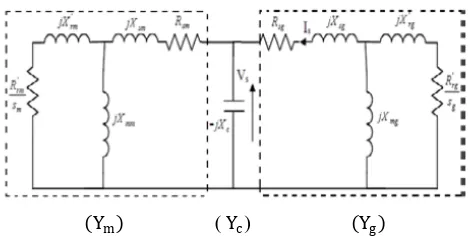
Nodal admittance equations are obtained for the following equivalent circuit [4]
(Ym) ( Yc) (Yg)
Fig. 3 (a) Per Phase Equivalent Circuit of Self Excited Induction Generator Feeding an Induction Motor Pump The nodal current equation is given as:
𝑉𝑠 𝑌𝑔+ 𝑌𝑐+ 𝑌𝑚 = 0 (1)
where
𝑌𝑔is the total admittance of induction generator.
𝑌𝑐 is capacitive admittance
and 𝑌𝑚 is the total admittance of induction motor
𝑌𝑐= 𝑗 𝑎
𝑋𝑐 (2)
𝑌𝑔 =
𝑌𝑔1(𝑌𝑔2+𝑌𝑔3)
𝑌𝑔1+𝑌𝑔2+𝑌𝑔3 (3)
𝑌𝑔1 = 1
𝑅𝑠𝑔+𝑗𝑎𝑋𝑠𝑔, 𝑌𝑔2= 1
𝑗𝑎𝑋𝑚𝑔, 𝑌𝑔3= 1 𝑎𝑅 𝑟𝑔
𝑎 −𝑏+𝑗𝑎𝑋𝑟𝑔
(4)
where a is p.u frequency and b is p.u speed.
Speed (PU) Frequency (PU) Speed (PU) Frequency (PU) 1 0.9987 0.6 0.5978
0.9 0.8986 0.5 0.4974 0.8 0.7984 0.4 0.3967 0.7 0.6982 0.3 0.2955 For calculations the p.u speed (b) is taken as 0.3 and the p.u frequency (a) as 0.2955.
Ym= 1 RM+jXM =
RM RM2+(XM)2−
XM
RM2+(XM)2 (5)
Under steady state self excitation, 𝑌𝑚≠ 0, therefore 𝑌𝑔 + 𝑌𝑐+ 𝑌𝑚 = 0. On solving the real and imaginary terms we get RG
RG2+(XG)2− RM
RM2+(XM)2= 0 (6) a
Xc− XG RG2+(XG)2−
XM
RM2+(XM)2= 0 (7)
The expression for 𝑎𝑚𝑎𝑥 on substituting RM = ∞ and XM=0 in equation (6), is given as
𝑎𝑚𝑎𝑥 = 𝑏 − 𝑏 2
1− 1− 𝑏 𝑐 𝑏
2
1+𝑅 𝑠𝑔 𝑅 𝑟𝑔 1+
𝑋 𝑟𝑔 𝑋 𝑚𝑔
2 (8)
Further substituting all the values, we obtain 𝑎𝑚𝑎𝑥= 0.2954
where
𝑏𝑐= 2𝑅𝑠𝑔
𝑋𝑚𝑠 𝑅𝑟𝑔 𝑅𝑠𝑔 1 +
𝑋𝑟𝑔 𝑋𝑚𝑔
2
= 0.1505 (9)
Substituting RM = ∞ and XM = 0 in (7) gives
𝑋𝑐 = 𝑎𝑚𝑎𝑥2 𝑋𝑠𝑔+
𝑎𝑋𝑚𝑔 𝑎−𝑏 2𝑋𝑟𝑔 𝑋𝑚𝑔+𝑋𝑟𝑔 +𝑅𝑟𝑔2
𝑎−𝑏 2 𝑋𝑚𝑔+𝑋𝑟𝑔 2+𝑅𝑟𝑔2 = 6.4078 (10)
Thus
𝐶𝑚𝑖𝑛 = 1
2𝜋50.𝑋𝑐 = 496.75 𝜇𝐹 (11)
𝐶𝑚𝑖𝑛 is the minimum capacitance to provide the self excitation. Practically, terminal capacitor C with a value slightly
greater than 𝐶𝑚𝑖𝑛 should be selected to provide self excitation. 3.2. L C Resonance Principle:
A method based on the combination of the principle of L-C resonance and non linear magnetization characteristic of the generator is used from Fig. 3(b). [5]
The analysis is made by short circuiting the rotor terminals and adding an excitation capacitance across the stator terminals.
Fig. 3 (c) per phase equivalent circuit of a SEIG at no load
At no load the rotor is considered as an open circuit and the L-C circuit obtained in Fig. 3 (c) is used to determine the value of excitation capacitance. To generate a voltage, the circuit must be at resonance.
Therefore,
Xc
F2= Xls+ Xm (12)
Vg
F = Vs
F Xm
Xls+Xm (13)
Synchronous speed test results are obtained to find the relationship betweenVg
F and Xm, where Vg is airgap voltage, F is
p.u frequency and Xm is the magnetising reactance. The relationship between Vs and Xm is obtained as Vs
F Xm
Xls+Xm = k0+ k1Xm+ k2Xm 2+ k
3Xm3 (14)
After determining the values of Xm andXc, C can be obtained as C = 1 2ПfbF2(X
ls+Xm) (15)
On substituting, fb = 50, F = 0.2955 and Xls + Xm= Xs = 2𝜋 ∗ 50 ∗ Ls as specified above, the value of capacitance
obtained is 506.69𝜇𝐹.
IV. CONCLUSION:
The squirrel cage induction generator due to its ruggedness, low cost of construction, less maintenance and suitability for isolated operation, is an inexpensive alternative to synchronous generators. For isolated generation in remote areas a variable capacitance is required to build up the voltage in an SEIG. For efficient conversion of wind energy into electrical energy the induction generator needs to operate smoothly, giving sustained generated voltage at the stator terminals without any transients. Therefore, calculation of the capacitance value of the capacitor bank is critical for the desired operation of the induction generator. Thus the value of excitation capacitance required has been calculated.
The calculated value of the excitation capacitance for the given input parameters is tabulated below: Table 2: The calculated capacitance values:
Machine Input Parameters Results (Calculated 𝐶𝑚𝑖𝑛)
L C Resonance Principle Nodal Admittance Approach 3Kw, 220/380V, 12.4/7.2A, 4 pole, 50Hz, R
s=2.2Ω,
R
r=2.68Ω, Ls=Lr=229mH, Lm=217mH,
p.u frequency a= 0.2955 and p.u speed b = 0.3
506.69 𝜇𝐹 496.75𝜇𝐹
Thus the value of capacitance required for self excitation in an induction generator has been calculated using Nodal admittance approach and LC resonance principle. The Nodal admittance approach gives a lower value of excitation capacitance. It requires greater and lengthy calculations as compared to the other method.
REFERENCES
[1]Rajesh Kumar Thakur, Vivek Agarwal, and Paluri S. V. Nataraj, “A reliable and accurate calculation of excitation capacitance value for an induction generator based on interval computation technique”, IJAC November 2011, 429-436, DOI: 10.1007/s11633-011-0600-6.
[2] Roger J. Vieira, A. M. Sharaf, Adel Elgammal, “Design of self-excited induction generators for wind applications”, CCECE 2011, IEEE. [3] R.C. Bansal, “Three Phase Self Excited Induction Generators: An Overview”, IEEE Transactions on Energy Conversion, Vol.20, No.2, June 2005.
[4] A. Abbou, M. Barara, A. Ouchatti, M. Akherraz, and H. Mahmoudi, “Capacitance required analysis for self-excited induction generator”, JATIT, Vol.55 No.3, ISSN: 1992-8645, 30th Sept., 2013.